Page is loading ...

System design : Satisfactory perfor-
mance of a central exhaust ventilation
system requires the proper integration
of all the components, compatible ex-
haust grilles, and wall/roof caps, proper
duct design for friction losses, consid-
eration of acoustic and vibration prop-
erties of the fan and its mounting, acous-
tic properties of the exhaust grilles, con-
sideration of the mode of operation,
whether continuous, or automatically
controlled by timer, dehumidistat, occu-
pancy sensor, etc., installation in a
heated or unheated space, with consid-
eration for the potential of condensation
in the ducting or fan housing.
Inspect the carton upon receipt, to
insure the fan has not been damaged in
transit. If damaged, it is the responsibil-
ity of the recipient to file a damage claim
with the carrier. American ALDES Ven-
tilation Corporation is not responsible
for damage incurred during shipment.
Handle the unit with care to prevent
damage to the housing and other com-
ponents. Store the unit indoors if pos-
sible. If outdoor storage is required,
protection against moisture and dirt is
necessary.
Unpack the unit, taking care to look for
any loose components among the pack-
ing material. Make certain that the fan
housing and the blower is free of any
loose packing material or small parts. If
not removed before startup, damage
and injury may result from solid objects
discharged by the blower. Inspect for
damage, loose or missing parts.
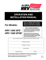
Install the unit in its final location. The
fan may be installed in a mechanical
room, crawl space or attic. It is de-
signed to be placed on a flat surface, as
shown in Figure 1, supported by its
rubber feet to provide vibration isola-
tion. Additional foam may be required
to completely isolate vibration. Alterna-
tively, it may be suspended as shown in
Figure 2, using threaded rods, perfo-
rated steel strips, or 90 lb. load-rated
chains. Sufficient room (minimum 15")
should be left above the fan to allow
MPV/SPV INSTALLATION,
OPERATION, AND MAINTENANCE
INSTRUCTIONS
MODELS:
SPV200, SPV300,
MPV200/4, MPV200/8, MPV300/4,
MPV300/6,MPV300/8, MPV300/12
# 161R
removal of the top panel with the at-
tached blower assembly; otherwise
servicing will require the complete dis-
assembly of the duct and mounting
rods.
Ducting may be flexible or rigid, de-
pending on local codes. If permitted by
code, insulated flexible ducting is rec-
ommended for at least several feet on
each duct connection, to limit fan noise
at the outlet grilles. Ducting should
conform to NFPA 90A and meet the
requirements of Underwriters Labora-
tory as a Class O or Class 1 duct to
specification UL 181, Standard for Fac-
tory-Made Air Ducts and Duct Connec-
tors. Metal ducting must be sealed on
both the end joints and longitudinal
seams to assure proper airflows at the
exhaust grilles.
COLD CLIMATE
PRECAUTIONS
If installed in an unheated space, in
severe climates, there is a possibil-
ity of condensation forming in the
fan housing or ducting components.
The housing is insulated to prevent
condensation in the fan housing,
but should condensation occur as a
result of severely cold temperatures,
or cyclical operation of the fan, a
condensation drain can be installed.
Some models are provided with a
drain. Others can be retrofitted.
Condensation can be avoided by
continuous operation of the fan. If
operated intermittently, the fan
housing will cool down, even though
it is insulated, and condensation
may occur inside the fan housing.
The discharge must be fitted with a
backdraft damper at the fan or roof/
wall cap to limit slowly exfiltrating
air. A backdraft damper installed at
each exhaust grille will be even
more effective in reducing the po-
tential for condensation when the
fan is cycled on and off. Insulated
ducting must be used where ex-
posed to cold attic or crawl space
temperatures, to avoid condensa-
tion in the ducting.
READ AND SAVE THESE INSTRUCTIONS
CAUTION
For General Ventilating Use Only.
Do Not Use to Exhaust Hazardous or
Explosive Materials and Vapors.
WARNING
TO REDUCE THE RISK OF FIRE, ELEC-
TRIC SHOCK, OR INJURY TO PERSONS,
OBSERVE THE FOLLOWING:
A. Use this unit only in the manner
intended by the manufacturer. If
you have any questions, contact
the manufacturer.
B. Before servicing or cleaning unit,
switch power off at service panel
and lock service panel to prevent
power from being switched on
accidentally. When the service
disconnecting means cannot be
locked, securely fasten a promi-
nent warning device, such as a
tag, to the service panel.
In addition to the following
manufacturer’s instructions, it is neces-
sary to comply with federal, state, and
local government codes. Your pur-
chase of this American ALDES ventila-
tion system represents an investment
in the health and comfort of the occu-
pants, as well as an investment in the
protection of the building from the dam-
aging effects of excessive indoor hu-
midity.
This model of central exhaust ventila-
tor, whether MPV (Multi-Port Ventila-
tor) or SPV (Single-Port Ventilator) is
intended for installation in a remote
location or mechanical room to provide
quiet exhaust of stale, humid, or other-
wise polluted air from bathrooms, the
kitchen, laundry, or storage rooms, via
exhaust grilles and ducting to the cen-
trally located fan, which is ducted to the
outdoors. Some models may also be
used as supply ventilators or recirculat-
ing central ventilators for the introduc-
tion of outdoor air, raising the tempera-
ture of the fresh air by mixing with
recirculated indoor air. When used with
adjustable balancing grilles or ALDES’
CAR
TM
, (Constant Airflow Regulators),
and compatible roof/wall caps, ducting,
etc, the fan is the heart of a complete
pre-engineered ventilation system.

1
2
ROOF CAP
6" OR 8" INSULATED
FLEX DUCT
6" INSULATED
FLEX DUCT
3" INSULATED
FLEX DUCT
ACCESSORY PLENUM
VIBRATION
ISOLATION FEET
PLYWOOD BASE
3" OR 4" EXHAUST
DUCT CONNECTIONS
MOUNTING MPV/SPV ON PLYWOOD BASE IN ATTIC
ROOF LINE
OPTIONAL (MPV 300)
ELECTRICAL BOX
SIDE
VIEW
S
S
S
END
VIEW
CHAIN
"S" HOOK
ROOF LINE
S
ROOF CAP
"S" HOOK
HANGING MPV/SPV WITH CHAIN IN ATTIC
*NOTE: 3" Ducting may be substituted for 4"
diameter duct to permit installation in partition
walls. Smaller diameter ducting has increased
resistance to airflow. For each foot of 3"
ducting substituted for 4" diameter duct re-
duce the allowable duct length by 3 feet. If
longer duct runs are required than permitted in
the table above use smooth ducting and/or
increase the diameter.
TABLE OF AIRFLOWS AND DUCT LENGTHS
Intake Duct to fan Fan Discharge Duct
AIRFLOW Maximum Duct Length from grille to fan (FT) Assumes Low pressure drop venthood
CFM 3"Smooth 3" Flexible 4" Smooth 4" Flexible TOTAL MAXIMUM
Duct Duct Duct Duct EXHAUST RATE LENGTH
10 225 180 900 640 (CFM) (FT)
15 105 90 400 300
20 65 50 260 180
25 45 30 175 120
30 30 25 130 85
35 25 20 95 65
40 20 15 75 50
45 15 10 60 40
50 10 10 50 30
MPV 300 ONLY
6" Smooth Duct 6" Flexible Duct
50 400 250
75 200 120
100 110 70
125 70 50
150 50 30
MPV 200 Models W/6" duct:
75 to 150 25'
150 to 250 10'
MPV 300 Models W/8" duct:
150 to 300 10'
FOR EACH ELBOW DEDUCT:
3" DIAM - 3' 4" DIAM - 4'
6" DIAM - 7' 8" DIAM - 9'
(Flexible)
This information is provided
to assist the designer and
installer in assuring proper
airflows at the exhaust grilles.
The data provided assumes
the use of ALDES CAR’s
(Constant Airflow Regulators)
to provide balanced airflows.
If manually balancing grilles
or dampers are used instead,
the same maximum duct
lengths should still be used,
since they impose a pressure
drop similar to that of a
Constant Airflow Regulator.
The length of ducting should
be limited to the values
specific for each fan model
shown in the tables. Other-
wise, reduced airflows will
result from duct resistance.
Refer to Manual D by the Air-
Conditioning Contractors of
America (ACCA), or HVAC
Systems Duct Design by the
Sheet Metal and Air Condi-
tioning Contractors National
Association, Inc. (SMACNA),
for more detailed design
methods.
TABLE OF AIRFLOWS AND DUCT LENGTHS SPV MODELS
Fan Discharge Duct
(with low pressure drop vent hood)
SPV 200 SPV 300
Intake Duct to fan
Maximum Duct Length (FT)
100 380 240
125 260 145
150 160 90 840 470
175 110 65 620 360
200 70 40 480 275
225 45 25 350 175
250 35 20 260 130
275 125 60
300 40 20
MAXIMUM
LENGTH
(FT)
8" FLEXIBLE
DUCT
8" SMOOTH
DUCT
6" FLEXIBLE
DUCT
6" SMOOTH
DUCT
AIRFLOW
(CFM)
TOTAL
EXHAUST RATE
(CFM)
SPV 200 Models W/6" duct:
75 to 150 25'
150 to 250 10'
SPV 300 Models W/8" duct:
150 to 300 10'
FOR EACH ELBOW DEDUCT:
3" DIAM - 3' 4" DIAM - 4'
6" DIAM - 7' 8" DIAM - 9'

DISASSEMBLY
Turn off all power to the unit. The blower
may be inspected and cleaned by re-
moving the screws from the top panel. It
may be necessary to disconnect the
wiring from the junction box. Grasp the
top panel and gently lift it straight up,
until the blower housing is completely
clear of the sides. The motor and blower
assembly are now easily accessible for
service.
MAINTENANCE
Monthly: Clean the exhaust grilles
and filters, if so equipped.
Annually: To ensure the maximum
efficiency of the fan unit, is recom-
mended to clean the inside of the fan
box as well as the blower wheel.
CAUTION: Automatically operated
device—to reduce risk of injury dis-
connect from the power supply be-
fore servicing.
CAPACITOR
MOTOR
JUNCTION
BOX
L1-115 V
NEUTRAL
GROUND
GREEN
BLACK
WHITE
FIELD WIRING
FACTORY WIRING
COIL
L2
HONEYWELL FAN
CONTROL CENTER
REMOTE LOW VOLTAGE SWITCHES/KITCHEN, BATHS, ETC.
R
G
N.O.
JUNCTION
BOX
120 V
NEUTRAL
GROUND
GREEN-YELLOW
BLACK
WHITE
CAPACITOR
MOTOR
FIELD WIRING
FACTORY WIRING
DISCONNECT
SWITCH
CAPACITOR
MOTOR
115 V
NEUTRAL
GROUND
GREEN
BLACK
WHITE
DISCONNECT
SWITCH
WIRING ENCLOSURE ON FAN
SWITCH LEG
MANUAL SWITCH
CRANK TIMER
DEHUMIDSTAT, CO2-CONTROL,
OR OCCUPANCY SENSING, ETC.
TIME OF DAY TIMER
SWITCHES IN BATHROOMS, KITCHEN OR LAUNDR
Y
LINE VOLTAGE REMOTE
SWITCHING INSTALLATION
STANDARD WIRING
INSTALLATION
LOW VOLTAGE INSTALLATION
WARNING
TO REDUCE THE RISK OF FIRE,
ELECTRIC SHOCK, OR INJURY TO
PERSONS, OBSERVE THE FOL-
LOWING:
A. Installation Work and Electrical Wir-
ing Must Be Done By Qualified
Person(s) In Accordance With All Ap-
plicable Codes And Standards, Includ-
ing Fire-Rated Construction.
B. Sufficient air is needed for proper
combustion and exhausting of gases
through the flue (chimney) of fuel burn-
ing equipment to prevent backdrafting.
Follow the heating equipment
manufacturer’s guideline and safety
standards such as those published by
the National Fire Protection Association
(NFPA), and the American Society for
Heating, Refrigeration and Air Condi-
tioning Engineers (ASHRAE), and the
local code authorities.
C. When cutting or drilling into wall or
ceiling, do not damage electrical wiring
and other hidden utilities.
D. Ducted fans must always be vented
to the outdoors.
E. If this unit is to be installed over a
tub or shower, it must be marked as
appropriate for the application.
F. NEVER place a switch where it can
be reached from a tub or shower.
Provide disconnect switch in vicinity
of fan, to permit servicing fan, in ac-
cordance with NEC and local codes.
Auxilliary switches and controls:
For continuous use, such as multi-
family ventilation systems, usually the
fan is not controlled by the occupants.
A control switch may be installed to
be used only by the building owners
and maintenance staff.
For intermittent use, as in single family
homes, the fan may be controlled re-
motely by switches in bathrooms, kitchen,
etc. These may be line voltage switches
wired in parallel to the disconnect switch
serving the fan, or low-voltage switches
connected to a fan relay center ( SPST).
WIRING
ELECTRICAL DATA
SPV 200, SPV 300,
MPV 200 MPV 300
Series Series
120 V. 120 V.
60 Hz 60 Hz
1.2 Amp. 1.5 Amp.
125 W. 145 W.
1600 RPM 1500 RPM
DISCLAIMER
IT IS THE RESPONSIBILITY OF
THE CONTRACTOR/INSTALLER
TO DETERMINE THE SUITABILITY
OF THIS EQUIPMENT WITH RE-
SPECT TO THE POTENTIAL FOR
BACK DRAFTING NATURALLY
VENTED FLUE DEVICES AND/OR
AFFECTING RADON ENTRY.

BACKDRAFTING
For installations in which the fan is connected to a range hood, or if an exhaust grille connected
to the fan is located above or near the cooking surface, as shown below, be sure to observe the
following safety warnings:
WARNING WARNING
WARNING
TO REDUCE THE RISK OF FIRE, USE ONLY METAL DUCTWORK.
(Use only galvanized steel ductwork.)
Use only galvanized steel ductwork in accordance with all
applicable codes.
(Note: If the fan is not connected to a range hood, or a grille in the
vicinity of the cooking surface, other approved ducting may be used as
described in "Ducting" section of basic instructions.)
TO REDUCE THE RISK OF A RANGE
TOP GREASE FIRE:
A. Never leave surface units unat-
tended at high settings. Boilovers
cause smoking and greasy
spillovers that may ignite. Heat
oils slowly on low or medium
settings.
B. Always turn hood ON when cook-
ing at high heat or flambeing
food (i.e. Crepe Suzette, Cher-
ries Jubilee, Peppercorn Beef
Flambe).
C. Clean ventilating fans frequently.
Grease should not be allowed to
accumulate on fan or filter.
D. Use proper pan size. Always use
cookware appropriate for the size
of the surface element.
TO REDUCE THE RISK OF INJURY TO PERSONS IN THE EVENT OF A RANGE
TOP GREASE FIRE, OBSERVE THE FOLLOWING
a
:
A. SMOTHER FLAMES with a close-fitting lid, cookie sheet, or metal tray,
then turn off the burner. BE CAREFUL TO PREVENT BURNS. If the
flames do not go out immediately EVACUATE AND CALL THE FIRE
DEPARTMENT.
B. NEVER PICK UP A FLAMING PAN — You may be burned.
C. DO NOT USE WATER, including wet dishcloths or towels — a violent
steam explosion will result.
D. Use an extinguisher ONLY if:
1. You know you have a Class ABC extinguisher, and you already know
how to operate it.
2. The fire is small and contained in the area where it started.
3. The fire department is being called.
4. You can fight the fire with your back to an exit.
the case of continuous exhaust, even
though often at lower flow rates, the
potential for backdrafting the flue of
these appliances does exist, and repre-
sents a dangerous situation. The Na-
tional Fuel Gas Code, available from
the American Gas Association, Appen-
dix H, provides a Recommended Pro-
cedure for Safety Inspection of an Ex-
isting Appliance Installation. This pro-
cedure should be followed to determine
the presence of adequate combustion
air, while all exhaust fans are operating
at maximum speed, and all doors and
windows are closed.
In the event that backdrafting occurs,
steps must be taken to provide suffi-
cient combustion air to the furnace or
boiler, following the guidelines of the
National Fuel Gas Code and all state
and local codes.
In especially tight homes heated with
naturally vented appliances, such as
gas, oil or wood-fired furnaces, boilers,
stoves or fireplaces, the exhaust sys-
tem may produce sufficient negative
pressure indoors to induce the
backdrafting of flue gases. This is quite
a common, though intermittent
occurence, with conventional exhaust
systems, such as vented kitchen range
hoods, clothes dryers, bath fans, etc. In
WARRANTY
The entire unit is guaranteed for 3 years, from date of shipment, against all manufacturing defects provided the material has been
installed and operated per manufacturer’s instructions and under normal conditions. Warranty is limited to the repair or replacement
of the material upon its return freight paid to our factory. This warranty is not transferable and is limited to the original end user.
161R-8-03
4537 NORTHGATE COURT
SARASOTA, FL 34234-2124, USA
Tel: 941 • 351- 3441
Fax: 941 • 351- 3442
http://www.americanaldes.com
email: [email protected]
VENTILATION
a
Based on "Kitchen Firesafety Tips" published by NFPA.

75 to
150 CFM
MPV 200 Models
150 to
250 CFM
MPV 300 Models
150 to
330 CFM
25'
W/ 6"
DUCT:
10'
W/8"
DUCT:
10'
4" FLEXIBLE
DUCT
AIRFLOW
(CFM)
4" SMOOTH
DUCT
TOTAL EXHAUST
RATE (CFM)
MAXIMUM LENGTH
(FEET)
10 900 640
15 400 300
20 260 180
25 175 120
30 130 85
35 95 65
40 75 50
45 60 40
50 50 30
For each 4" elbow, deduct 3 feet.
4" Intake Duct from grille to fan
Maximum Duct Length from grille to fan (Feet)
Fan Discharge Duct to outdoors
(with low pressure drop vent hood)
/