Page is loading ...

YSI Model 85
Handheld Oxygen,
Conductivity, Salinity,
mg/L
C
and Temperature
System
Operations
Manual


i
CONTENTS
SECTION 1 Introduction....................................................................................................................1
SECTION 2 Preparing The Meter....................................................................................................3
2.1 Unpacking.............................................................................................................................3
2.2 Warranty Card.......................................................................................................................3
2.3 Batteries ................................................................................................................................3
2.4 Calibration/Storage Chamber...............................................................................................5
2.5 Hand Strap ............................................................................................................................5
2.6 The Meter Case.....................................................................................................................5
SECTION 3 Preparing The Probe....................................................................................................7
3.1 Membrane Cap Installation................................................................................................7
SECTION 4 Overview Of Operation................................................................................................9
SECTION 5 Calibration...................................................................................................................11
5.1 Calibration of Dissolved Oxygen.......................................................................................11
5.2 Calibration of Conductivity................................................................................................12
SECTION 6 Advanced Conductivity Setup...................................................................................15
6.1 Changing the Temperature Coefficient..............................................................................15
6.2 Changing the Reference Temperature...............................................................................16
6.3 Changing from Autoranging to Manual Ranging .............................................................16
SECTION 7 Making Measurements ..............................................................................................17
7.1 Turning the Instrument On.................................................................................................17
7.2 The Measurement Modes of the Model 85........................................................................17
7.3 Autoranging and Range Searching....................................................................................18
7.4 The Backlight......................................................................................................................18
SECTION 8 Saving Data...................................................................................................................21
8.1 Saving Data to Memory .....................................................................................................21
8.2 Recalling Stored Data.........................................................................................................21
8.3 Erasing Stored Data............................................................................................................22
SECTION 9 Maintenance................................................................................................................23
9.1 Cleaning and Storage..........................................................................................................23
SECTION 10 Principles Of Operation............................................................................................25
10.1 Temperature Effect on Conductivity ...............................................................................25

ii
SECTION 11 Discussion Of Measurement Errors........................................................................27
11.1 Dissolved Oxygen Measurement Errors..........................................................................27
11.2 Conductivity Measurement Errors...................................................................................29
11.3 Dissolved Oxygen Probe Precautions..............................................................................31
SECTION 12 Troubleshooting.........................................................................................................33
SECTION 13 Warranty And Repair...............................................................................................35
SECTION 14 Accessories And Replacement Parts.......................................................................40
APPENDIX A Specifications ............................................................................................................45
APPENDIX B Required Notice........................................................................................................47
APPENDIX C Temperature Correction Data ...............................................................................51
APPENDIX D Conversion Chart.....................................................................................................53
APPENDIX E Oxygen Solubility Table..........................................................................................52
APPENDIX F Calibration Values Table.........................................................................................54

YSI, Incorporated Model 85 1
SECTION 1 INTRODUCTION
The YSI Model 85 Handheld Dissolved Oxygen, Conductivity, Salinity and Temperature System is
a rugged, micro-processor based, digital meter with an attached YSI combination conductivity and
dissolved oxygen probe.
The YSI Model 85 is designed for use in field, lab, and process control applications as well as for
environmental, aquaculture, and industrial uses. The Model 85 is available with cable lengths of
either 10, 25, 50 or 100 feet. The body of the probe has been manufactured with stainless steel to add
rugged durability and sinking weight. The probe also utilizes our easy to install cap membranes for
measuring dissolved oxygen.
The YSI Model 85 probe is a non-detachable, combination sensor designed specifically for the YSI
Model 85 Handheld System. The conductivity portion is a four-electrode cell with a cell constant of
5.0/cm ±4%. The dissolved oxygen portion is a polargraphic Clark type sensor.
The Model 85’s microprocessor allows the system to be easily calibrated for dissolved oxygen or
conductivity with the press of a few buttons. Additionally, the microprocessor performs a self-
diagnostic routine each time the instrument is turned on. The self-diagnostic routine provides you
with useful information about the conductivity cell constant and function of the instrument circuitry.
The system simultaneously displays temperature (in °C), along with one of the following
parameters: dissolved oxygen in either mg/L (milligrams per liter) or % air saturation; conductivity;
temperature compensated conductivity; (in µS/cm or mS/cm), and salinity (in parts per thousand
{ppt}).
The system requires only a single calibration regardless of which dissolved oxygen display you use.
The calibration of conductivity is not required but is available. A single calibration will adjust the
instrument, regardless if you are reading conductivity or temperature compensated conductivity.
You can switch between all of these parameters with the push of a single key.
A calibration\storage chamber is built into the instrument case. A small sponge in the chamber can
be moistened to provide a water saturated air environment that is ideal for air calibration of the
dissolved oxygen probe. This chamber also provides a convenient place to store the probe when the
system is not in use, and provides protection for the electrodes within the conductivity probe. The
Model 85 case is also waterproof (rated to IP65). You can operate your Model 85 in the rain without
damage to the instrument.
Six AA-size alkaline batteries power the instrument. A new set of alkaline batteries will provide
approximately 100 hours of continuous operation. When batteries need to be replaced, the LCD will
display a “LO BAT” message.

Introduction Section 1
YSI, Incorporated Model 85 2

SECTION 2 PREPARING THE METER
2.1 UNPACKING
When you unpack your new YSI Model 85 Handheld Dissolved Oxygen, Conductivity, Salinity
and Temperature System for the first time, check the packing list to make sure you have received
everything you should have. If there is anything missing or damaged, call the dealer from whom
you purchased the Model 85. If you do not know which of our authorized dealers sold the system
to you, call YSI Customer Service at 800-765-4974 or 937-767-7241, and we'll be happy to help
you.
2.2 WARRANTY CARD
Before you do anything else, please complete the Warranty Card and return it to YSI. This will
record your purchase of this quality instrument in our computer system. Once your purchase is
recorded, you will receive prompt, efficient service in the event any part of your YSI Model 85
should ever need repair and we will be able to quickly verify the warranty period.
2.3 BATTERIES
There are a few things you must do to prepare your YSI Model 85 for use. First, locate the six AA-
size alkaline batteries that were included in your purchase. Use a screwdriver or a small coin to
remove the thumbscrew on the bottom of the instrument. This thumbscrew holds the battery-
chamber cover in place. The battery-chamber cover is marked with the words "OPEN" and
"CLOSE."
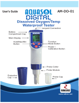
Hand strap
Battery chamber
cover
Thumb screw Polarity marking
O-rings
YSI, Incorporated Model 85 3

Preparing the Meter Section 2
YSI, Incorporated Model 85 4
NOTE: On some models, the battery cover thumbscrew may be unscrewed by hand (a screwdriver
may not be required).
There is a small label inside each of the two battery-chamber sleeves. These labels illustrate the
correct way to install the batteries into each sleeve of the battery-chamber.
NOTE: It is very important that the batteries be installed ONLY as illustrated. The instrument will
not function and may be damaged if the batteries are installed incorrectly.

Preparing the Meter Section 2
Turn the instrument on by pressing and releasing the ON/OFF button on the front of the instrument.
The liquid crystal display (LCD) should come on. Allow a few seconds for the instrument to
complete its diagnostic routine. Notice that the instrument will display the specific cell constant of
the conductivity probe during this diagnostic routine. If the instrument does not operate, consult the
section entitled Troubleshooting.
You may also want to take the instrument into a dark room and with the instrument ON, hold down
the LIGHT button. The instrument backlight should illuminate the LCD so that the display can be
easily read.
2.4 CALIBRATION/STORAGE CHAMBER
Calibration/Storage
Chamber
The Model 85 has a convenient calibration storage
chamber built into the instruments' side. This chamber
provides an ideal storage area for the probe during
transport and extended non-use. If you look into the
chamber you should notice a small round sponge in the
bottom of the chamber. Carefully put 3 to 6 drops of
clean water into the sponge. Turn the instrument over
and allow any excess water to drain out of the chamber.
The wet sponge creates a 100% water saturated air
environment for the probe, which is ideal for dissolved
oxygen calibration.
2.5 HAND STRAP
The hand strap is designed to allow comfortable operation of the Model 85 with minimum effort. If
the hand strap is adjusted correctly, it is unlikely that the instrument will be easily dropped or
bumped from your hand. See figure on previous page.
To adjust the hand strap on the back of the meter, unsnap the vinyl cover and pull the two Velcro
strips apart. Place your hand between the meter and the strap and adjust the strap length so that your
hand is snugly held in place. Press the two Velcro strips back together and snap the vinyl cover back
into place.
2.6 THE METER CASE
The meter case is sealed at the factory and is not intended to be opened, except by authorized service
technicians. Do not attempt to separate the two halves of the meter case as this may damage the
instrument, break the waterproof seal, and will void the manufacturer's warranty.
YSI, Incorporated Model 85 5

Preparing the Meter Section 2
YSI, Incorporated Model 85 6

YSI, Incorporated Model 85 7
SECTION 3 PREPARING THE PROBE
The YSI Model 85 dissolved oxygen probe is shipped dry. The protective membrane cap on
the probe tip must be removed and replaced with KCl solution and a new membrane cap
before using the probe. Follow the instructions below to install KCl solution and the new
membrane cap.
3.1 MEMBRANE CAP INSTALLATION
To install a new membrane on your YSI Model 85 dissolved oxygen probe:
1. Unscrew and remove the probe sensor guard.
2. Unscrew and remove the old membrane cap.
3. Thoroughly rinse the sensor tip with distilled water.
4. Prepare the electrolyte according to the directions on the KCl solution bottle.
5. Hold the membrane cap and fill it at least 1/2 full with the electrolyte solution.
6. Screw the membrane cap onto the probe moderately tight. A small amount of
electrolyte should overflow.
7. Screw the probe sensor guard on moderately tight.
Screw Ca
p
on
moderately tight
Unscrew Guard
Unscrew Ca
p
Fill Membrane
with KCL Solution
Screw Guard on
moderately tight

Preparing the Probe Section 3
YSI, Incorporated Model 85 8

YSI, Incorporated Model 85 9
SECTION 4 OVERVIEW OF OPERATION
The following diagram is an overview of the operation of the Model 85. See the following sections
for details of operation.

Overview of Operation Section 4
YSI, Incorporated Model 85 10

YSI, Incorporated Model 85 11
SECTION 5 CALIBRATION
5.1 CALIBRATION OF DISSOLVED OXYGEN
To accurately calibrate the YSI Model 85 you will need to know the approximate altitude of
the region in which you are located.
1. Ensure that the sponge inside the instrument's
calibration chamber is wet. Insert the probe into
the calibration chamber.
2. Turn the instrument on by pressing the
ON/OFF button on the front of the instrument.
Press the MODE button until dissolved oxygen
is displayed in mg/L or %. Wait for the
dissolved oxygen and temperature readings to
stabilize (usually 15 minutes is required).
3. Use two fingers to press and release both the
UP ARROW and DOWN ARROW buttons at the same time.
Calibration/Storage
Chamber
4. The LCD will prompt you to enter the local altitude in hundreds of feet. Use the arrow
keys to increase or decrease the altitude. When the proper altitude appears on the LCD, press
the ENTER button once.
EXAMPLE: Entering the number 12 here indicates 1200 feet.
5. The Model 85 should now display CAL in the lower left of the display, the calibration
value should be displayed in the lower right of the display and the current % reading (before
calibration) should be on the main display. Make sure that the current % reading (large
display) is stable, then press the ENTER button. The display should read SAVE then should
return to the Normal Operation Mode.
Each time the Model 85 is turned off, it may be necessary to re-calibrate before taking
measurements. All calibrations should be completed at a temperature which is as close as
possible to the sample temperature. Dissolved oxygen readings are only as good as the
calibration.

Calibration Section 5
YSI, Incorporated Model 85 12
5.2 CALIBRATION OF CONDUCTIVITY
IMPORTANT: System calibration is rarely required because of the factory calibration of the
YSI Model 85. However, from time to time it is wise to check the system calibration and make
adjustments when necessary.
Prior to calibration of the YSI Model 85, it is important to remember the
following:
1. Always use clean, properly stored, NIST traceable calibration solutions (see Accessories and
Replacement Parts). When filling a calibration container prior to performing the calibration
procedures, make certain that the level of calibrant buffers is high enough in the container to
cover the entire probe. Gently agitate the probe to remove any bubbles in the conductivity cell.
2. Rinse the probe with distilled water (and wipe dry) between changes of calibration solutions.
3. During calibration, allow the probe time to stabilize with regard to temperature (approximately
60 seconds) before proceeding with the calibration process. The readings after calibration are
only as good as the calibration itself.
4. Perform sensor calibration at a temperature as close to 25°C as possible. This will minimize any
temperature compensation error.
Follow these steps to perform an accurate calibration of the YSI Model 85:
1. Turn the instrument on and allow it to complete its self-test procedure.
2. Select a calibration solution that is most similar to the sample you will be measuring.
• For sea water choose a 50 mS/cm conductivity standard (YSI Catalog# 3169)
• For fresh water choose a 1 mS/cm conductivity standard (YSI Catalog# 3167)
• For brackish water choose a 10 mS/cm conductivity standard (YSI Catalog # 3168)
3. Place at least 3 inches of solution in a clean glass beaker.
4. Use the MODE button to advance the instrument to display conductivity.
5. Insert the probe into the beaker deep enough so that the oval-shaped hole on the side of the probe
is completely covered. Do not rest the probe on the bottom of the container -- suspend it above
the bottom at least 1/4 inch.
6. Allow at least 60 seconds for the temperature reading to become stable.
7. Move the probe vigorously from side to side to dislodge any air bubbles from the electrodes.
8. Press and release the UP ARROW and DOWN ARROW buttons at the same time.
The CAL symbol will appear at the bottom left of the display to indicate that the instrument is now
in Calibration mode.

Calibration Section 5
YSI, Incorporated Model 85 13
10.00 µS
24.8
o
C
CAL
9. Use the UP ARROW or DOWN ARROW button to adjust the reading on the display until it
matches the value of the calibration solution you are using.
10. Once the display reads the exact value of the calibration solution being used (the instrument will
make the appropriate compensation for temperature variation from 25°C), press the ENTER
button once. The word “SAVE” will flash across the display for a second indicating that the
calibration has been accepted.
The YSI Model 85 is designed to retain its last conductivity calibration permanently. Therefore,
there is no need to calibrate the instrument after battery changes or power down.

Calibration Section 5
YSI, Incorporated Model 85 14

YSI, Incorporated Model 85 15
SECTION 6 ADVANCED CONDUCTIVITY SETUP
The default settings of the YSI Model 85 are appropriate for the vast majority of measurement
applications. However, some measurement applications require very specific measurement criteria.
For that reason, we have made the YSI Model 85 flexible to accommodate these “advanced users.”
If, for example, you are using the YSI Model 85 for a process control application that requires that
the conductivity readings be compensated to 20
o
C instead of 25
o
C -- this is the section to read. Or,
if your application for the YSI Model 85 involves the measurement of a very specific saline solution,
the default temperature coefficient may need to be changed to get the very best measurement of that
specific salt.
IMPORTANT: There is never a need to enter Advanced Setup Mode unless your special
measurement application calls for a change in reference temperature and or temperature coefficient.
Therefore, unless you are certain that your application requires a change to one or both of these
criteria, do not modify the default reference temperature (25
o
C) or the default temperature
coefficient (1.91%).
6.1 CHANGING THE TEMPERATURE COEFFICIENT
Follow these steps to modify the temperature coefficient of the Model 85.
1. Turn the instrument on and wait for it to complete its self-test procedure.
2. Use the MODE button to advance the instrument to display conductivity.
3. Press and release both the DOWN ARROW and the MODE buttons at the same time.
The CAL symbol will appear at the bottom left of the display. The large portion of the display will
show 1.91 % (or a value set previously using Advanced Setup).
4. Use the UP ARROW or DOWN ARROW button to change the value to the desired new
temperature coefficient.
5. Press the ENTER button. The word “SAVE” will flash across the display for a second to
indicate that your change has been accepted.
6. Press the MODE button to return to normal operation; the CAL symbol will disappear from the
display.

Advanced Conductivity Setup Section 6
YSI, Incorporated Model 85 16
6.2 CHANGING THE REFERENCE TEMPERATURE
Follow these steps to modify the reference temperature of the Model 85.
1. Turn the instrument on and wait for it to complete its self-test procedure.
2. Use the MODE button to advance the instrument to display conductivity.
3. Press and release both the DOWN ARROW and the MODE buttons at the same time.
The CAL symbol will appear at the bottom left of the display. The large portion of the display will
show 1.91 % (or a value set previously using Advanced Setup).
4. Press and release the MODE button; the large portion of the display will show
25.0C (or a
value set previously using Advanced Setup).
5. Use the UP ARROW or DOWN ARROW button to change the value to the desired new
reference temperature (any value between 15
o
C and 25
o
C is acceptable).
6. Press the ENTER button. The word “SAVE” will flash across the display for a second to
indicate that your change has been accepted.
7. The instrument will automatically return to normal operation mode.
6.3 CHANGING FROM AUTORANGING TO MANUAL RANGING
If your application is easier to perform using a manual range that you select, the YSI Model 85
allows you to turn off the default autoranging feature. While you are making conductivity or
temperature compensated conductivity measurements, simply press and release the UP ARROW
button. Each additional press of the UP ARROW button will cycle the Model 85 to a different
manual range until you return again to autoranging. Five pushes of the UP ARROW button will
cycle the Model 85 through the four manual ranges and return the instrument to autoranging.
NOTE: You may see an error message in some manual ranges if the manual range selected is not
adequate for the sample you are measuring. If this happens, simply press and release the UP
ARROW button again until a range is selected which is suitable for your sample. If you get lost and
don’t know if you’re in a manual range or autoranging, simply turn the instrument off and back on.
Also note that the conductivity units will flash while you are in manual range. The instrument will
always default to autoranging when first turned on.
The four ranges of the YSI Model 85 are:
Range 1 Range 2 Range 3 Range 4
0 to 499.9 µS/cm 0 to 4999 µS/cm
0 to 49.99 mS/cm 0 to 200.0 mS/cm
/