Page is loading ...

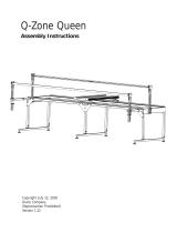
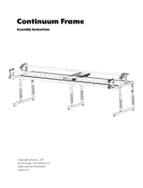
Dream Fabric Frame
Assembly Instructions
Copyright January 1, 2016
Jim M. Bagley, GraceWood, Inc
(Reproduction Prohibited)
Version 2.4

Table Of Contents
Parts List 3
Step 1: Table Set Up 6
Step 2: Install the Hand Wheel 8
Step 3: Install the Front Rail 8
Step 4: Top Plate Assembly 11
Step 5: Place the Sewing Machine 12
Step 6: Install the Back Rail 13
Step 7: Adjust Fabric Height 15
Step 8: Control Box Set-up 16
Step 9: Sure Stitch Installation 17
2

3
2.5mm Allen
Wrench (1)
Sure Stitch Box
Back Rail Clamp (3)
Front Rail Clamp (2)Front Rail (1)
Back Rail (1)
Table Top (1)
Power Supply (1)
Encoder with Encoder
Cable(2)
Control Box (1)
Box 1
Box 2
Display Box (1)
Ziptie (8)
Ziptie Mount (6) Velcro Strap (6)
Sure Stitch Display Cable (1)
Sure Stitch Sewing Machine
Cable (1)
Parts List
Cloth Leaders (4)

Inner Box 3
4
Left Leg (1) Right Leg (1)
Sewing Machine Clamp (4)
Top Plate (1)
Bottom Plate (1)
Carriage Bolt and Clamp (1)
Side Rail Clamp (2)
Handle Crossbar (1)
Handle Left (1) Handle Right (1)
Box 2 Continued
Bungee Clamp with
Bungee Stop (4)
Inner Box 1
Inner Box 2

5
3mm Allen
Wrench (1)
5mm Allen
Wrench (1)
6mm Allen
Wrench (1)
M8 x 16mm SBHCS (20)
M6 x 10mm SBHCS (4)
M10 Washer (1) M10 x 80mm SBHCS (1)
17mm Open End Wrench (1)
M8 x 85mm Shoulder Bolt (1)
4mm Allen
Wrench (1)
Inner Box 5
Inner Box 4
M8 x 50mm SBHCS (5)
Fabric Hook Holder (5)Corner Brace (4)
Long Knob (1)Large Hand Wheel (1)
Box 2 Continued

Parts Needed:
Step 1: Table Set Up
6
1. Right Leg (1)
2. Left Leg (1)
3. Table Top (1)
4. M8 x 16mm SBHCS (25)
5. 5mm Allen Wrench (1)
6. 4mm Allen Wrench (1)
7. Corner Brace (4)
Average sitting height is 4 holes from bottom
1-3 Replace each Height Screw and tighten
each Centering Screw
Height Screw
1-1 Remove Height Screws and Loosen
Centering Screws
Height Screw
Centering Screws
1-2 Adjust Table height

7
1-6 Tilt Table Upright
1-7 Attach Corner Braces to each corner
1-4 Attach Hooks to Table
M8 x 50mm
SBHCS
1-5 Attach Legs to Table with the Hooks
facing the front of the Legs.
M8 x 16mm
SBHCS
Note: Leave bolts loose, they will be tightened in
a further step.
Note: Leave screws loose, they will be tightened
in a further step.
M8 x 16mm
SBHCS (4)
Front
Rear

Parts Needed:
Parts Needed:
1. 6mm Allen Wrench (1)
2. Large Hand Wheel (1)
3. Long Knob (1)
4. M10 Washer (1)
5. M8 x 85mm Shoulder Bolt (1)
6. M10 x 80mm SBHCS (1)
1. Front Rail (1)
2. 3mm Allen Wrench (1)
3. 5mm Allen Wrench (1)
Step 2: Install the Hand Wheel
Step 3: Install the Front Rail
2-1 Attach the Long Knob
3-1 Remove Rail End Cap on each Front
Corner Post
8
2-2 Attach the Large Hand Wheel
M8 x 85mm
Shoulder Bolt
M10 Washer
M10 x 80mm
SBHCS
3-2 Insert Front Rail into the right Front
Corner Post
Align grooves in
handwheel with
hand wheel collar
Note: Make sure gears engage before moving
on. If gears are not properly engaged pull legs
in/out to align gears.

9
3-3 Re-install Rail End Cap onto the right
Front Corner Post
Note: Be sure the side rails and front rail line up
so that a long rubber edge on each rail is the
highest part of each rail before installing cap.
Rubber edge is
highest part of rails
3-6 Re-install Rail End Cap onto the left
Front Corner Post
Note: Be sure the side rails and front rail line up
so that a long rubber edge on each rail is the
highest part of each rail before installing cap.
Rubber edge is
highest part of rails
You may need to tilt
the top of the Leg
inward
3-5 Insert Front Rail into the left Front
Corner Post
3-4 Tighten each bolt with the Allen
Wrench oriented verticle as shown in Fig.
3-4a until difcult to turn, then turn each
bolt 1/4 a rotation with the Allen Wrench
oriented horizontal as shown in Fig. 3-4b.
Fig. 3-4a Fig. 3-4b

10
3-8 Tighten the (4) loose screws on the
underside of the table from Step 1-5
3-9 Tighten (16) loose screws on the Coner Braces from Step 1-7
3-7 Tighten each bolt with the Allen
Wrench oriented verticle as shown in Fig.
3-7a until difcult to turn, then turn each
bolt 1/4 rotation with the Allen Wrench
oriented horizontal as shown in Fig. 3-7b.
Fig. 3-7a Fig. 3-7b

11
4-4 Place Bottom Plate onto Frame and Top Plate onto Bottom Plate
Parts Needed:
1. Right Handle (1)
2. Left Handle (1)
3. Top Plate (1)
4. Handle Crossbar (1)
5. Carriage Bolt and Clamp (1)
6. Bottom Plate (1)
7. M6 x 10mm SBHCS (4)
8. 4mm Allen Wrench (1)
Step 4: Top Plate Assembly
4-2 Un-thread Clamp from Carriage Bolt 4-3 Assemble Cross Brace with Carriage
Bolt and Clamp
4-1 Attach Handles
M6 x 10mm
SBHCS (4)
*Note: the Carriage Bolt may need to be
twisted to pass through both handles.
*Note: Make sure
Bottom Plate is
Oriented with
Sewing Machine
Stop towards
back of frame
Sewing
Machine
Stop
*Note: may
need to loosen
screws in cross
brace to get
carriage bolt
through , then
retighten screws

Parts Needed:
1. Sewing Machine
2. Cam Clamp (4)
Step 5: Place the Sewing Machine
12
5-1 Place Sewing Machine onto Top Plate
using the placement instructions below.
Slide each Clamp into the grooves on the
Top Plate and lock against Machine.
Note: Innovis XV 8500D will not use the Front 2 Clamps.
Brother 1500:
Center from front to back and from side to side.
Center from side to side. Align the back of the
throat with the verticle handlebar
Innovis VQ 2400; Innovis XV 8500D:
Placement Instructions:

13
6-3 Loosen each Knob on the back of each
Rail Holder
6-4 Insert Back Rail through the throat of
the Sewing Machine
Note: You may need to pull rails upward to allow the
levers to be pressed in.
Final height will be adjusted in later step.
Parts Needed:
1. Back Rail (1)
2. 4mm Allen Wrench (1)
Step 6: Install the Back Rail
6-2 Raise Rails to Top Slot6-1 Loosen the Set Screws on each Corner
Post

14
6-6 Insert the right end of the Back Rail
into the right back Rail Holder
6-5 Insert the left end of the Back Rail into
the left back Rail Holder
6-7 Tighten each Knob on the back of each
Rail Holder
6-8 Adjust leveling feet height until table
is level using the (1) 17mm Open End
Wrench
Heighten Table
Lower Table

Parts Needed:
1. 4mm Allen Wrench (1)
Step 7: Adjust Fabric Height
7-2 Tighten set screws in Rail Holders
1/4 in
Above
Machine
7-1 Move Back Rail 1/4” above Machine
15
Note: refer to step 6-2 for instructions on how to raise and
lower the rails.
7-3 Move the Sewing Machine so that the
Needle is 1” away from the Back Rail. Hold
the Machine in place as you adjust the
Carriage Stop by loosening the knob and
sliding the Sewing Machine stop against
the back wheel. This will be adjusted again
in the Fabric Installation instructions.
Knob
Sewing Machine Stop
Needle 1in
away from
Back Rail
Note: Do not over tighten set screws.

16
8-2 Move the Control Jumpers to the correct pins based on your Machine Model.
8-1 Open the Control Box
Parts Needed:
1. Control box
Step 8: Control Box Set-up
JP1
J3
10 1 2 3
Brother 1500S:
JP1: ON
JP2: ON
JP3: OFF
JP4: OFF
J3-4 ON
Innovis 1500D,
Innovis 2500D,
Innovis 4500D:
JP1
J3
10 1 2 3
JP1: OFF
JP2: ON
JP3: ON
JP4: OFF
J3-2 ON
JP1
J3
10 1 2 3
Innovis VQ2400, Innovis VM6200,
Innovis XV8500D, NV6000D,
NV6700, NV6750D, Innovis VM 5100
Note: 6000 series machines are not
multifunction compatible
JP1: OFF
JP2: OFF
JP3: ON
JP4: ON
J3: OFF

9-2 Clamp Display Box onto Crossbar next
to the Handle on the Left or Right Side
17
9-3 Secure the Display Box with (1) M4 x
16mm SBHCS
Parts Needed:
1. Display Box (1)
2. Control Box (1)
3. Sure Stitch Display Cable (1)
4. Sewing Machine Cable (1)
5. Power Supply (1)
6. Encoder with Encoder Cable(2)
7. Velcro Strap (6)
8. Zip Tie (8)
9. Zip Tie Mount (6)
10. M4 x 16mm SBHCS (1)
11. M6 x 20mm SBHCS (2)
12. 4mm Allen Wrench (1)
13. 2.5mm Allen Wrench (1)
Step 9: Sure Stitch Installation
Display Box
M4 x 16mm
SBHCS
9-1 Remove (1) M4 x 16mm SBHCS from
Display Box
M4 x 16mm
SBHCS

18
Control
Box
9-5 Place Control Box on back of Machine
9-6 Plug in one end of the Display Cable
into the Display Box
9-7 Plug in the other end of the Display
Cable into the Control Box
9-4 Remove Sticky Tape Paper Backing
from Control Box
Note: Be sure the
arrow is on the back
side of the Cable

9-8 Use the Velcro Straps to Secure Display
Cable
Velcro (x5)
9-9 Remove Back Right Wheel and Screw
from Top Plate
19
9-11 Remove Back Left Wheel and Screw
from Bottom Plate
9-10 Install Encoder to Top Plate with M6
x 20mm SBHCS and Removed Wheel
M6 x 20mm
SBHCS
Note: Rotate Encoder until the Encoder Spring is
partially compressed and then tighten the M6 X
20mm SBHCS for better accuracy.
Back Right
Wheel from
Top Plate
Back Right
Wheel from
Top Plate
Back of Frame
Back of Frame
Bottom
Plate
Bottom
Plate
Top Plate
Top Plate
Back Left Wheel
from Bottom Plate
Back Left Wheel
from Bottom Plate

20
9-14 Plug in Power Supply to Control Box 9-15 Plug Power Supply to an outlet.
Note: Plug in Sure Stitch unit before sewing
machine is turned on, or an error may occur.
9-13 Plug Encoder Cables into Control Box
9-12 Install Encoder to Bottom Plate with
M6 x 20mm SBHCS and Removed Wheel
M6 x 20mm
SBHCS
Note: Rotate Encoder until the Encoder Spring is
partially compressed and then tighten the M6 X
20mm SBHCS for better accuracy.
/