
3227484
Rev. F
AUGUST 2012
RNH SERIES
HIGH TEMPERATURE REFRIGERATED DRYERS
OPERATOR
MANUAL
RNH20 RNH25 RNH35
RNH50 RNH75 RNH100
RNH125

2
GENERAL SAFETY INFORMATION
1. Pressurized devices
This equipment is a pressure containing device.
• Donotexceedmaximumoperatingpressureas
shown on equipment serial number tag.
• Makecertainequipmentisdepressurizedbefore
servicing.
2. Electrical
This equipment requires electricity to operate.
• Installequipmentincompliancewithnationaland
local electrical codes.
• StandardequipmentissuppliedwithNEMA1elec-
tricalenclosuresandisnotintendedforinstallation
inhazardousenvironments.
• Disconnectpowersupplytoequipmentwhenper-
forminganyelectricalservicework.
3. Breathing air
• Airtreatedbythisequipmentmaynotbesuitable
forbreathingwithoutfurtherpurication.Referto
OSHAstandard1910.134fortherequirementsfor
breathing quality air.

3
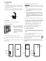
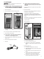
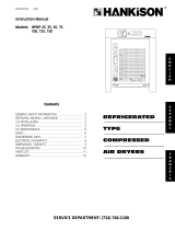
IO
Serial Number
Tag
Ambient Air Filter
Electrical
Connection
Control
Panel
Air Inlet
Connection
Serial
Number
Tag
Drain
Connection
Air Outlet
Connection
Separator and
Integral Filter
Left Side Front BackRight Side
Strainer
(shipped
separately)
Drain
Mechanism
Pipe Nipple
2. Location in the compressed air system
A. Maximumworkingpressure-250psig,
17.6kgf/cm
2
.Donotexceedunit’sMaximumWorking
Pressure.
1) Formaximumcapacity,installunitinairsystem
athighestpressurepossible(e.g.beforepressure
reducingvalves)
2) Formaximumcapacity,installunitatcoolestcom-
pressedairtemperaturepossible.Maximuminlet
compressedairtemperature:180°F,82°C.Ifinlet
airexceedsthistemperature,precooltheairby
extendingthepipingbetweenthecompressorand
the dryer.
B. AirOutlet-Connectairoutlettodownstreamairlines.
C. By-passpiping-Ifservicingtheunitwithoutinterrupt-
ingtheairsupplyisdesired,pipingshouldincludeinlet
and outlet isolation valves and an air by-pass valve.
D. Condensatedrain-Itisadvisabletoconnectdrain
outlet to the condensate drainage system.
NOTE:Draindischargeisatsystempressure.Drainline
should be anchored to prevent whipping.
1.4 Electrical connections
A. Dryerisdesignedtooperateonpowersupply(voltage)
listedonserialnumbertaglocatedonthebackofthe
dryer.
B. Dryerissuppliedwithanelectricalcord.Installinre-
ceptacleofpropervoltage.
NOTE:Models50and75(115vonly)-Installplug
inreceptacleratedfor20amps.Unitsaresup-
pliedwith20ampplug.
NOTE:Refrigerationsystemisdesignedtoruncontinu-
ouslyandshouldNOTbewiredtocycleon/offwiththeair
compressor.
1.0 INSTALLATION
1.1 Location
A. Aircompressorintake-Locateaircompressorsothat
contaminantspotentiallyharmfultothedryerarenot
drawn into the air system.
B. Freeairow-Donotblockeithersideofthecabinet.
Observe minimum installation clearances as shown.
1.2 Mounting
Dryerissuitableforoororshelfmounting.
1.3 Piping connections
A. AirInlet-Connectcompressed
airlinefromaircompressorto
air inlet using strainer supplied.
1. Installstrainer(includedin
shippingcarton)priorto
dryer inlet using pipe nipple
supplied or other piping as
required.
NOTE:Observeowdirectionarrowsonstrainer.
NOTE:Installstrainerwhereitiseasilyaccessibleforclean-
ing.
NOTE:Usevibrationdampener,ifvibrationexistsinairline
at inlet to dryer.
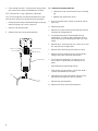
24"
12"
wall
6"
36"
Plug

4
2.0 OPERATION
NOTE:Installationsabove6000feet,1825meters
Unitisadjustedtooperateinaltitudesupto6000feet,
1825meters.Ifunitisinstalledinanaltitudeabovethis,
andhasnotbeenpresetatthefactoryforthisaltitude,
contactManufacturer’sServiceDepartment.
2.1 Start-up
Startrefrigerationsystembypushingtheon/offswitch
totheONposition(depressrockerswitchonsidemarked
“I”).
NOTE:Thefaultlightmayilluminatewhenunitisener-
gized.Lightshouldgooutapproximately5minutesafter
start-up.Iflightremainslitafter30minutesorillumi-
natesaftergoingout,refertoTroubleshootingGuide.
2.2 Operating check points
Checkthefollowingonaperiodicbasis:
A. RockerswitchisintheONposition.
B. Amberfaultlightisout.
C. Condensateisbeingregularlydischarged.
2.3 Minimum/maximum operating conditions
A. Minimum/Maximumairpressure:20/250psig,
1.4/17.6kgf/cm
2
B. Maximuminletairtemperature:180°F,82°C
C. Minimum/Maximumambienttemperature:
40/110°F,4/43°C
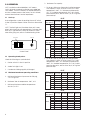
ControlPanel
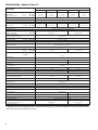
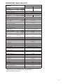
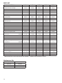
2. Fordryerswithanaftercoolerinstalledupstream
Flowcapacityinscfm(m
3
/min)@100°F,38°Cinlet
temperature,100°F,38°Cinletpressuredewpoint,
100°F,38°Cambienttemperature,50°F,10°Coutlet
pressuredewpoint,andlessthan10psi,0.7kgf/cm
2
pressure drop.
D. Maximumowcapacity
1. Fordryerswithoutanaftercoolerinstalledupstream.
Flowcapacityinscfm(m
3
/min)@180°F,82°Cinlet
temperature,160°F,71°Cinletpressuredewpoint,
95°F,35°Cambienttemperature,50°F,10°Coutlet
pressuredewpoint,andlessthan5psi,0.35kgf/cm
2
pressure drop.
I
O
On/Off Switch
Fault Light
60 HZ
Inlet Pressure
psig (kgf/cm
2
)
175 (12.3) 150 (10.6) 125 (8.8) 100 (7.0)
Model
20 23 (0.65) 22 (0.62) 20 (0.57) 18 (0.51)
25 29 (0.82) 27 (0.76) 25 (0.71) 23 (0.65)
35 41 (1.16) 38 (1.08) 35 (0.99) 32 (0.91)
50 58 (1.64) 54 (1.53) 50 (1.42) 45 (1.27)
75 87 (2.46) 81 (2.29) 75 (2.12) 68 (1.93)
100 116 (3.29) 108 (3.06) 100 (2.83) 91 (2.58)
125 145 (4.12) 135 (3.82) 125 (3.54) 114 (3.23)
50 HZ
Inlet Pressure
psig (kgf/cm
2
)
175 (12.3) 150 (10.6) 125 (8.8) 100 (7.0)
Model
20 20 (0.57) 18 (0.51) 17 (0.48) 15 (0.42)
25 24 (0.68) 23 (0.65) 21 (0.59) 19 (0.54)
35 31 (0.88) 29 (0.82) 27 (0.76) 24 (0.68)
50 58 (1.64) 54 (1.53) 50 (1.42) 45 (1.27)
75 71 (2.01) 66 (1.87) 61 (1.73) 55 (1.56)
100
97 (2.75)
90 (2.55) 83 (2.35)
76 (2.15)
125 121 (3.43) 112 (3.17) 104 (2.95) 95 (2.69)
60 HZ
Inlet Pressure
psig (kgf/cm
2
)
175 (12.3) 150 (10.6) 125 (8.8) 100 (7.0)
Model
20 32 (0.91) 30 (0.85) 28 (0.79) 25 (0.71)
25 40 (1.13) 37 (1.05) 34 (0.96) 31 (0.88)
35 55 (1.56) 51 (1.44) 47 (1.33) 43 (1.22)
50 78 (2.21) 73 (2.07) 67 (1.90) 61 (1.73)
75 118 (3.34) 110 (3.12) 102 (2.89) 92 (2.61)
100 157 (4.45) 146 (4.14) 136 (3.85) 123 (3.48)
125 197 (5.58) 183 (5.18) 170 (4.82) 155 (4.39)
50 HZ
Inlet Pressure
psig (kgf/cm
2
)
175 (12.3) 150 (10.6) 125 (8.8) 100 (7.0)
Model
20 27 (0.76) 25 (0.71) 23 (0.65) 21 (0.59)
25 33 (0.93) 31 (0.88) 29 (0.82) 26 (0.74)
35 43 (1.22) 40 (1.13) 37 (1.05) 33 (0.93)
50 78 (2.21) 73 (2.07) 67 (1.90) 61 (1.73)
75 96 (2.72) 90 (2.55) 83 (2.35) 75 (2.12)
100 131 (3.71) 122 (3.46) 113 (3.20) 102 (2.89)
125 164 (4.65) 152 (4.31) 142 (4.02) 129 (3.65)

5
3.0 MAINTENANCE
DRYERISAPRESSURECONTAININGDEVICE.
DEPRESSURIZEBEFORESERVICING.
3.1 Ambient air filter - Clean accumulated dust and
dirt from ambient air filter monthly or more of-
ten if air flow across the condenser is impeded.
A. Removetoppanel.
B. Removeambientairlterbyslidingupwards.
C. Washwithsoapandwaterandallowtodrybeforere-
installing.
NOTE:Donotusesolventstocleanambientairlter.
D. Reinstalllterandtoppanel.
3.2 Inlet strainer - clean inlet strainer monthly or
more often if rapid clogging occurs.
A. Shut-offcompressedairsupplytothestrainerand
depressurize.
B. Removescreenandcleanorreplace.
C. Reinstall.
Screen
3.3 Replace separator/filter element yearly or
more often if pressure drop across the dryer is
excessive.
A. Shut-offcompressedairsupplytothedryerandde-
pressurize.
B. Removetoppanel.
C. Removetwoscrewsholdingsidepanelandremove
side panel by sliding upwards.
D. Disconnectdraintubefrombulkheadttingin
cabinetbase.Toremove,presstheplasticcollarin,
towardthetting,whilepullingthetubeoutofthe
tting.
E. Removebowl-pushbowlup,turnbowl1/8thturnto
yourleft,andpullstraightdown.
F. Cleanlterbowl.
G. Replaceelement.
1. Replacingcompleteelement
a) Pulloffoldelementanddiscard.
b) MakecertainO-ringinsidetopofreplacement
elementisinplaceandpushelementontolter
head.
2. Replacingsleeveonly
a) Pullelementstraightdowntoremove.
b) Removeboltandbottomcapandremovedispos-
ableltersleeve.
c) Cleanseparatorcorewithsoapandwaterifnec-
essary
d) Slidenewltersleeveoverseparatorcoreand
replace bottom cap and hand tighten bolt.
e) MakecertainO-ringinsidetopofelementisin
placeandpushelementontolterhead.

6
H. AftermakingsurethatO-ringandwavespringinside
topofbowlareinplace,reassemblebowltohead.
NOTE:MakecertainO-ringisgenerouslylubricated
NOTE:Wavespringendsshouldbepointeddowntopre-
ventthewavespringfrominterferingwithreassembly.
I. Reconnectdraintubetobulkheadttingbypushing
tubeintottinguntilitlocksinposition.
J. Reinstallsideandtoppanels.
K. Repressurizedryerandresumeoperation.
Element o-ring
Separator Element
Bowl o-ring
Drain Mechanism
Wave Spring
Tube
Hose
Barb
3.4 Automatic condensate drain
• Checkdailytobesureautomaticdrainisdischarg-
ing.
• Replacedrainmechanismyearly.
A. Shut-offcompressedairsupplytothedryerandde-
pressurize.
B. Removetoppanel.
C. Removetwoscrewsholdingsidepanelthenremove
side panel by sliding upwards.
D. Disconnectdraintubefrombulkheadttingin
cabinetbase.Toremove,presstheplasticcollarin,
towardthetting,whilepullingthetubeoutofthe
tting.
E. Removebowl-pushbowlup,turn1/8thturntoyour
left,andpullbowlstraightdown.
F. Removedraintubettingfrombottomofbowl.
G. Removeolddrainmechanismbyturningknurled
ttingtotheright(clockwise)andremove.
H. Installnewdrainmechanism.Ifnecessary,usea
wire or pencil to guide the new mechanism into
place.
I. Reassembledraintubettingtobowl.
J. AftermakingsurethatlargeO-ringinlterheadis
inplace,reassemblebowltohead.
K. Reconnectdraintubetobulkheadttingbypush-
ingtubeintottinguntilitlocksinposition.
L. Reinstalltopandsidepanels.
M. Repressurizedryerandresumeoperation.

7
TROUBLESHOOTING GUIDE
A) Water downstream of dryer
B) High pressure drop across
dryer
C) Fault Alarm
D) Refrigeration system not func-
tioning properly
1. Whendryeron/offswitchinonor
"I"position
2. Refrigerantcompressorcycleson
andoff
1. Residualfreemoistureremainingin
downstream pipelines
2. Airby-passsystemisopen
3. InletandOutletconnectionsare
reversed
4. Temperaturessurroundingair
linesdownstreamofdryerhave
dropped below dryers dew point
rating.
5.Excessivefreemoisture(bulkliquid)
at dryer inlet
6.Condensatenotbeingautomati-
cally drained
Drainmechanismiscloggedor
inoperative.
Drainlineisrestrictedorfrozen.
7.Dryeroverloadedresultinginel-
evated dew point.
8. Refrigerationsystemnotfunction-
ing properly resulting in elevated
dew point.
1. Inletairstrainerclogged
2.Excessiveairow
3.Separatorlterclogged.
4.Freezingofmoistureinevaporator
becauseofrefrigerationsystem
improperlyfunctioning.
1.Dryeroverloadedresultinginhigh
air outlet temperature.
2.Refrigerationsystemnotfunction-
ing properly resulting in high air
outlet temperature.
3.Unitfunctioningnormallybutther-
mostaticswitchismalfunctioning
or not securely mounted.
a. Powerfailure
b. Line disconnect switch open
c. Blownfuses,openbreaker
d.Faultywiring,looseterminals
a. Highorlowambientconditions
b.Ambientairlterclogged
c. Condensernsclogged
d.Fanmotororfancontrolswitch
malfunction
e. Refrigerantleak
f. Lowvoltage
Blow out system with dry air
Checkvalvepositions
Checkforcorrectconnection
Insulateorheattraceairlinesexposed
to low ambients or dry air to lower
dew point
Installseparatoraheadofdryer
Replacedrainmechanismifinopera-
tive
Open drain line
Checkinletairtemperatureandpres-
sure,owrate(compressorcapacity)
and ambient air temperature
SeeDbelow
Cleaninletairstrainer
Checkowrate
Replaceltersleeve
SeeDbelow
SeeA7
SeeDbelow
Contactqualiedrefrigerationrepair-
manormanufacturer’sservicedepart-
ment
Checkpowertounit
Closedisconnectswitch
Checkforcontinuity
Haveelectriciancheckelectricalcon-
nections
Checkminimum/maximumtempera-
ture ranges
Cleanambientairlter
Cleancondenser
Replacefanmotororfancontrol
switch
Contactqualiedrefrigerationrepair-
manormanufacturer'sservicedepart-
ment
Checkwiring
SYMPTOM POSSIBLE CAUSE(S) CORRECTIVE ACTION

8
SPECIFICATIONS - Models 20 thru 75
Description
Model
20 25 35 50 75
Operating Conditions
RatedCapacity
@125psig,8.8kgf/cm
2
*
scfm
m
3
/min
60 / 50 Hz
60 / 50 Hz
20/17
0.57/0.48
25/21
0.71/0.59
35/27
0.99/0.76
50/50
1.42/1.42
75/61
2.12/1.7
MaximumWorkingPressure 250psig(17.6kgf/cm
2
)
MaximumInletTemperature 180°F(82°C)
Min/Max.AmbientTemperature 40-110°F(4-43°C)
PressureDrop@
rated capacity
psi
(kgf/cm
2
)
60 / 50 Hz
60 / 50 Hz
4.5/2.9
(0.32/0.20)
3.3/2.4
(0.23/0.17)
4.7/2.9
(0.33/0.20)
4.5/4.5
(0.32/0.32)
3.8/2.2
(0.27/0.15)
Refrigeration System Data
CompressorType Hermetic,Rotary,PermanentSplitCapacitor
BTU/HR-RefrigerationOnly
@ASRE-TConditions
60 / 50 Hz 8720/7043 12500/9970
OutletAirTemperature
(nominal@ratedconditions)
155°F(68°C)
RefrigerantType R-407C
RefrigerantCharge oz(grams)
60 / 50 Hz
SeeDryerSerialTag
SuctionPressureSetting 67psig(4.7kgf/cm
2
)
FactoryTest(design)Pressure
highside/lowside
330/178psig(23.2/12.5kgf/cm
2
)
CondenserFanSwitchSetting(in-out) 240-180psig(16.9-12.7kgf/cm
2
)
AirFlowAcrossCondenser cfm
m
3
/min
60 / 50 Hz
60 / 50 Hz
280/235
(7.9/6.7)
620/515
(17.6/14.6)
Electrical Data
Unit
VAC/phase/Hz
115/1/60
115/1/60
Minimum/maximumvolts 98-127
FullLoadAmpS(FLA) 8.7 12.6
BranchCircuitFuseSize(amps) 15 20
Compressor
Volts/phase/Hz
115/1/60
RatedLoadamps(RLA) 7.5 11.0
LockedRotoramps(LRA) 44.0 67.0
Watts(input) 853 1220
Overload(External) ThermalandCurrent(AutoReset)
Condenserfanmotor
Volts/phase/Watts(output)
115/1/25 115/1/35
FullLoadAmps(FLA) 1.2 1.6
Unit
VAC/phase/Hz
220-240/1/50
220-240/1/50
Minimum/maximumvolts 198-264
FullLoadAmps(FLA) 3.4 6.0
BranchCircuitFuseSize(amps) 15
Compressor
Volts/phase/Hz
220-240/1/50
RatedLoadamps(RLA) 2.8 5.1
LockedRotoramps(LRA) 18.6 28.0
Watts(input) 690 990
Overload(External) ThermalandCurrent(AutoReset)
Condenserfanmotor
Volts/phase/Watts(output)
220-240/1/18.3 220-240/1/25.6
FullLoadAmps(FLA) 0.6 0.8
* Capacity @ 180°F, 82°C inlet temperature, 160°F, 71°C inlet pressure dew point, 95°F, 35°C ambient temperature, 50°F, 10°C outlet pressure dew
point, and less than 5 psi, 0.35 kgf/cm
2
pressure drop.

9
SPECIFICATIONS - Models 100 and 125
Description
Model
100 125
Operating Conditions
RatedCapacity
@125psig,8.8kgf/cm
2
*
scfm
m
3
/min
60 / 50 Hz
60 / 50 Hz
100/83
2.83/2.35
125/104
3.54/2.95
MaximumWorkingPressure 250psig(17.6kgf/cm
2
)
MaximumInletTemperature 180°F(82°C)
Min/Max.AmbientTemperature 40-110°F(4-43°C)
PressureDrop@
rated capacity
psi
(kgf/cm
2
)
60 / 50 Hz
60 / 50 Hz
3.5/2.6
(0.25/0.18)
4.6/3.1
(0.32/0.22)
Refrigeration System Data
CompressorType Hermetic,Rotary,PermanentSplitCapacitor
BTU/HR-RefrigerationOnly
@ASRE-TConditions
60 / 50 Hz 25140/20110
OutletAirTemperature
(nominal@ratedconditions)
155°F(68°C)
RefrigerantType R-407C
RefrigerantCharge oz(grams)
60 / 50 Hz
SeeDryerSerialTag
SuctionPressureSetting 67psig(4.7kgf/cm
2
)
FactoryTest(design)Pressure
highside/lowside
330/178psig(23.2/12.5kgf/cm
2
)
CondenserFanSwitchSetting(in-out) 240-180psig(16.9-12.7kgf/cm
2
)
AirFlowAcrossCondenser cfm
m
3
/min
60 / 50 Hz
60 / 50 Hz
830/690
(23.5/19.5)
Electrical Data
Unit
VAC/phase/Hz
208-230/1/60
230/1/60
Minimum/maximumvolts 187-253
FullLoadAmpS(FLA) 12.2
BranchCircuitFuseSize(amps) 20
Compressor
Volts/phase/Hz
208-230/1/60
RatedLoadamps(RLA) 11.3
LockedRotoramps(LRA) 71.0
Watts(input) 2530
Overload(Internal) ThermalandCurrent(AutoReset)
Condenserfanmotor
Volts/phase/Watts(output)
230/1/60
FullLoadAmps(FLA) 0.85
Unit
VAC/phase/Hz
220/1/50
220/1/50
Minimum/maximumvolts 207-242
FullLoadAmps(FLA) 14.1
BranchCircuitFuseSize(amps) 20
Compressor
Volts/phase/Hz
200-220/1/50
RatedLoadamps(RLA) 13.2
LockedRotoramps(LRA) 71.0
Watts(input) 2212
Overload(Internal) ThermalandCurrent(AutoReset)
Condenserfanmotor
Volts/phase/Watts(output)
230/1/50
FullLoadAmps(FLA) 0.85
* Capacity @ 180°F, 82°C inlet temperature, 160°F, 71°C inlet pressure dew point, 95°F, 35°C
ambient temperature, 50°F, 10°C outlet pressure dew point, and less
than 5 psi, 0.35 kgf/cm
2
pressure drop.

10
Models 20, 25, and 35
ELECTRICAL SCHEMATICS
3
LINE
SW
G
1
2
3
3
4
A
TEMPERATURE
FPS
8
FM
CONDENSER
FAN MOTOR
4
RC
HTS
7
5
M
LT
R
C S
6
REFRIGERANT
COMPRESSOR
4
4
HIGH
4
WIRING SCHEMATIC
2
3 1
OLT
14
Models 50 and 75
3
LINE
SW
G
1
2
3
3
4
A
TEMPERATURE
FPS
8
FM
CONDENSER
FAN MOTOR
4
RC
HTS
7
5
M
LT
R
C S
6
REFRIGERANT
COMPRESSOR
4
4
HIGH
4
WIRING SCHEMATIC
Models 100 and 125
FPS
TB
HTS
FM
OLT
LT
SW
M
Front of Dryer
(Outside)
Right Side of Dryer
(Inside)
COMPONENT LOCATIONS
RC
Models 20, 25, 35, 100, and 125
LT
SW
FPS
CT
HTS
FM
OLT
M
RC
Front of Dryer
(Outside)
Right Side of Dryer
(Inside)
COMPONENT LOCATIONS
LEGEND
SW - On/Off Switch
OLT - Thermal Overload
M - Compressor Motor
RC - Run Capacitor
HTS - High Temperature Switch
LT - Fault Light
FPS - Fan Pressure Switch
FM - Fan Motor
TB - Terminal Block
CT - Contactor w/115V Coil
Models 50 and 75

11
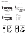
DIMENSIONS AND WEIGHTS
Models 20, 25, 35
Model Weight
20 79lbs(36kg)
25 80lbs(36kg)
35 81lbs(37kg)
718 mm
317 mm
105 mm
1.9/16 "
40 mm
5 mm
217 mm
1" 25 mm
6 mm
257 mm
5.1/16 "
128 mm
257 mm
216 mm
41 mm
130 mm
105 mm
287 mm
1.1/2"
38 mm
168 mm
21 mm
327 mm

12
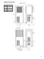
DIMENSIONS AND WEIGHTS
Models 50 and 75
Model Weight
50 150lbs(68kg)
75 155lbs(70kg)
933 mm
117 mm
1.1/2"
38 mm
429 mm
5 mm
419 mm
25 mm
21 mm
15 1/4"
387 mm
8 7/16"
213 mm
425 mm
6 mm
129 mm
39 mm
175 mm
160 mm
232 mm
59 mm

13
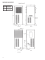
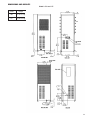
DIMENSIONS AND WEIGHTS
Models 100 and 125
Model Weight
100187lbs(85kg)
125189lbs(86kg)
1"
1"

14
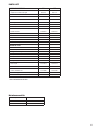
PARTS LIST
Maintenance Kits
For Dryer Models Kit Number
20,25,35 RNHFMK1
50, RNHFMK2
75 RNHFMK3
PARTS DESCRIPTION 20 25 35 50 75
Separator
*Separator/FilterCartridge
CE9-16 CE9-16 CE9-16 CE9-20 CE9-24
FilterSleeve CS9-16 CS9-16 CS9-16 CS9-20 CS9-24
*DrainMechanism 3152270 3152270 3152270 3152270 3152270
Bowl 3240333 3240333 3240333 3223457 3241108
*O-ring Bowl 3154585 3154585 3154585 3162913 3162913
Inlet (Compressed Air) Strainer
Strainer,inlet
4009634 4009634 4009634 4009635 4009635
*Screen,strainer 3230672 3230672 3230672 3230673 3230673
Electrical
Switchon/off
3230775 3230775 3230775 3230775 3230775
Light,Fault(amber)
115/1/60
3227423 3227423 3227423 3227423 3227423
Light,Fault(amber)
220-240/1/50
3227424 3227424 3227424 3227424 3227424
CordSet
115/1/60
3221571 3221571 3221571 3221572 3221572
CordSet
220-240/1/50
3221422 3221422 3221422 3221422 3221422
Capacitor,run
115/1/60
3220878 3220878 3220878 3220878 3220878
Capacitor,run
220-240/1/50
3220872 3220872 3220872 3220878 3220878
Switch,faultlightw/conn. 3240331 3240331 3240331 3240597 3240597
Condenser Fan
FanMotor
115/1/60
3228001 3228001 3228001 3227992 3227992
FanMotor
220-240/1/50
3228002 3228002 3228002 3227986 3227986
FanBlade
115/1/60
3219394 3219394 3219394 3219395 3219395
FanBlade
220-240/1/50
3219394 3219394 3219394 3219399 3219399
Refrigeration System
Compressor
115/1/60
3221265 3221265 3221265 3221267 3221267
Compressor
220-240/1/50
3221266 3221266 3221266 3221268 3221268
Condenser 3221323 3221323 3221323 3221324 3221324
Hotgasby-passvalve 3232549 3232549 3232549 3232526 3232526
Filter/Dryer 3223809 3223809 3223809 3223809 3223809
FanPressureSwitch 3230755 3230755 3230755 3230756 3230756
Cabinet
*Filter,AmbientAir
3223805 3223805 3223805 3223806 3223806
Grommet(light&switch,frontpanel) 3224016 3224016 3224016 3224016 3224016
Foot,mounting 3223838 3223838 3223838 3223838 3223838
* Maintenance kits for the above models are available "*" indicates items included in the kits.

15
PARTS LIST
Maintenance Kits
For Dryer Models Kit Number
100 RNHFMK4
125 RNHFMK4
PARTS DESCRIPTION 100 125
Separator
*Separator/FilterCartridge
CE9-24 CE9-24
FilterSleeve CS9-24 CS9-24
*DrainMechanism 3152270 3152270
Bowl 3241108 3241108
*O-ring Bowl 3162913 3162913
Strainer,inlet 4009636 4009636
*Screen,strainer 3230662 3230662
Electrical
Switchon/off
3230775 3230775
Light,Fault230v 3227424 3227424
CordSet 3221573 3221573
Capacitor,run
230/1/60
3264639 3264639
Capacitor,run
220/1/50
3264639 3264639
Switch,faultlightw/conn. 3240597 3240597
Condenser Fan
FanMotor 3227986 3227986
FanBlade 3219404 3219404
Refrigeration System
Compressor
230/1/60
3264172 3264172
Compressor
220/1/50
3264172 3264172
Condenser 3221325 3221325
Hotgasby-passvalve 3232526 3232526
Filter/Dryer 3223814 3223814
FanPressureSwitch 3230756 3230756
Cabinet
*Filter,AmbientAir
3223807 3223807
Grommet(light&switch,frontpanel) 3224016 3224016
Foot,mounting 3223838 3223838
* Maintenance kits for the above models are available "*" indicates
items included in the kits.

SERVICE DEPARTMENT: (724) 746-1100
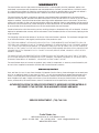
WARRANTY
Themanufacturerwarrantstheproductmanufacturedbyit,whenproperlyinstalled,operated,applied,and
maintainedinaccordancewithproceduresandrecommendationsoutlinedinmanufacturer’sinstructionmanu-
als,tobefreefromdefectsinmaterialorworkmanshipforaperiodasspeciedbelow,providedsuchdefectis
discoveredandbroughttothemanufacturer’sattentionwithintheaforesaidwarrantyperiod.
Themanufacturerwillrepairorreplaceanyproductorpartdeterminedtobedefectivebythemanufacturer
withinthewarrantyperiod,providedsuchdefectoccurredinnormalserviceandnotasaresultofmisuse,abuse,
neglectoraccident.Normalmaintenanceitemsrequiringroutinereplacementarenotwarranted.Thewarranty
coverspartsandlaborforthewarrantyperiodunlessotherwisespecied.Repairorreplacementshallbemadeat
thefactoryortheinstallationsite,atthesoleoptionofthemanufacturer.Anyserviceperformedontheproduct
byanyoneotherthanthemanufacturermustrstbeauthorizedbythemanufacturer.
Unauthorizedservicevoidsthewarrantyandanyresultingchargeorsubsequentclaimwillnotbepaid.Products
repairedorreplacedunderwarrantyshallbewarrantedfortheunexpiredportionofthewarrantyapplyingtothe
original product.
Theforegoingistheexclusiveremedyofanybuyerofthemanufacturer’sproduct.Themaximumdamagesliabil-
ityofthemanufactureristheoriginalpurchasepriceoftheproductorpart.
THEFOREGOINGWARRANTYISEXCLUSIVEANDINLIEUOFALLOTHERWARRANTIES,WHETHERWRITTEN,ORAL,OR
STATUTORY,ANDISEXPRESSLYINLIEUOFTHEIMPLIEDWARRANTYOFMERCHANTABILITYANDTHEIMPLIEDWARRAN-
TYOFFITNESSFORAPARTICULARPURPOSE.THEMANUFACTURERSHALLNOTBELIABLEFORLOSSORDAMAGEBY
REASONOFSTRICTLIABILITYINTORTORITSNEGLIGENCEINWHATEVERMANNERINCLUDINGDESIGN,MANUFACTURE
ORINSPECTIONOFTHEEQUIPMENTORITSFAILURETODISCOVER,REPORT,REPAIR,ORMODIFYLATENTDEFECTS
INHERENTTHEREIN.
THEMANUFACTURER,HISREPRESENTATIVEORDISTRIBUTORSHALLNOTBELIABLEFORLOSSOFUSEOFTHEPROD-
UCTOROTHERINCIDENTALORCONSEQUENTIALCOSTS,EXPENSES,ORDAMAGESINCURREDBYTHEBUYER,WHETH-
ERARISINGFROMBREACHOFWARRANTY,NEGLIGENCEORSTRICTLIABILITYINTORT.
Themanufacturerdoesnotwarrantanyproduct,part,material,component,oraccessorymanufacturedbyoth-
ersandsoldorsuppliedinconnectionwiththesaleofmanufacturer’sproducts.
Warranty Period
Partsandlaborfortwo(2)yearsfromthedateofshipmentfromthefactory;heatexchangersarecovered(parts
only)foranadditionalthree(3)years(totalofve[5]).Onunitsthatmanufacturerrequestsbereturnedtothe
factory,aonetimeremoval/reinstallationlaborallowanceasnotedintheServiceWarrantyPoliciesandProce-
duresHandbookwillapply.Freighttothefactoryfromtheinstallationsiteandtotheinstallationsitefromthe
factorywillbepaidbythemanufacturer;meansoftransportationtobespeciedbymanufacturer.
AUTHORIZATION FROM THE SERVICE DEPARTMENT IS NECESSARY BEFORE MATERIAL IS
RETURNED TO THE FACTORY OR IN-WARRANTY REPAIRS ARE MADE.
Curtis-Toledo, Inc.
1905 Kienlen Avenue, St. Louis Missouri 63133
WWW.FSCURTIS.COM
-
 1
1
-
 2
2
-
 3
3
-
 4
4
-
 5
5
-
 6
6
-
 7
7
-
 8
8
-
 9
9
-
 10
10
-
 11
11
-
 12
12
-
 13
13
-
 14
14
-
 15
15
-
 16
16


Ask a question and I''ll find the answer in the document
Finding information in a document is now easier with AI
Related papers
Other documents
-
Champion CRH 125 User manual
-
Champion CRN75 User manual
-
 FS-Curtis RNP35 User manual
-
-
BENDIX TCH-008-010 User manual
-
Emax HSP07V080V3P230 User manual
-
 HANKISON HPRP 100 User manual
-
ITT Conoflow Thermostat Installation guide
-
 Quincy Compressor QRHT Owner's manual
-
Ingersoll-Rand R Series Installation, Operation & Maintenance Manual


