Page is loading ...

3227447
Rev. A
AUGUST 2012
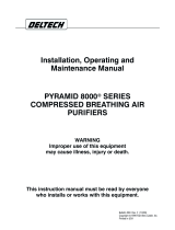
RNP SERIES
REFRIGERATED COMPRESSED AIR DRYERS
OPERATOR
MANUAL
RNP25 RNP35 RNP50

2
GENERAL SAFETY INFORMATION
1. PRESSURIZED DEVICES:
This equipment is a pressure containing
device.
• Donotexceedmaximumoperating
pressure as shown on equipment
serial number tag.
• Makesureequipmentisdepressurizedbefore
workingonordisassemblingitforservice.
2. ELECTRICAL:
This equipment requires electricity to
operate.
• Installequipmentincompliancewith
all applicable electrical codes.
• Standardequipmentissuppliedwithelectrical
enclosuresnotintendedforinstallationinhazardous
environments.
• Disconnectpowersupplytoequipmentwhen
performinganyelectricalservicework.
3. BREATHING AIR:
• Airtreatedbythisequipmentmay
notbesuitableforbreathingwithout
furtherpurication.
Refertoapplicablestandardsand
specicationsfortherequirements
forbreathingqualityair.
RECEIVING, MOVING, AND UNPACKING
A. RECEIVING
Thisshipmenthasbeenthoroughlychecked,packedand
inspectedbeforeleavingourplant.Itwasreceivedin
goodconditionbythecarrierandwassoacknowledged.
CheckforVisibleLossorDamage.Ifthisshipmentshows
evidenceoflossordamageattimeofdeliverytoyou,
insistthatanotationofthislossordamagebemadeon
the delivery receipt by the carrier’s agent.
B. UNPACKING
Checkforconcealedlossordamage.Whenashipment
hasbeendeliveredtoyouinapparentgoodorder,but
concealeddamageisfounduponunpacking,notifythe
carrier immediately and insist on his agent inspecting
the shipment. Concealed damage claims are not our
responsibilityasourtermsareF.O.B.pointofshipment.
C. MOVING
Inmovingortransportingdryer,donottipdryerontoits
side.
D. STORAGE
IMPORTANT:Donotstoredryerintemperaturesabove
130°F (54.4°C).

3
Compressor
Oil Removal
Filter
Aftercooler
Automatic Drain
Dryer
Separator
Receiver
TYPICAL COMPRESSED AIR SYSTEM
INSTALLATION
Ambient Air Temperature
Locatethedryerindoorswheretheambientairtemperature
willbebetween40°Fand100°F.Intermittentoperationat
ambient temperatures up to 113°F will not damage the dryer
but may result in a higher dew point or dryer shutdown
duetohighrefrigerantdischargepressure(seeFieldService
Guide).
Donotoperateair-cooleddryersatambientairtemperatures
below40°F.Suchoperationmayresultinlowsuction
pressure,causingfreeze-up.
Callyourlocaldistributorifprolongedoperationatambient
temperatures above 100°F or below 40°F is unavoidable.
Location and Clearance
Mountthedryeronalevelbase.Installthedryerinaclean,
well-ventilatedareatoreducefoulingofthecondensercoils
with dirt and dust.
Vaporsandcontaminantscorrosivetocopperandaluminum
mustnotbeintheareaofthedryeroraircompressorintake.
Allowatleast6inchesclearancefromthefrontandfromthe
condensercoilserviceaccess.Installthedryerwiththeframe
level.Anchorboltsarenotrequired.
System Arrangement
Liquidwaterintheinletairwilladverselyaffectthe
performanceofthedryer.Installthedryerdownstreamofan
aftercoolerorseparatorsothatthetemperatureofthedryer
inletairdoesnotexceed120°Fandtheinletairdoesnot
contain any liquid water.
Mostcompressedairsystemsrequireltersforremoval
ofsolidandliquidcontaminants.Whenanoil-removal
lterisused,itshouldbeinstalleddownstreamofthe
refrigerateddryer.Thedryerwillremovesomeentraineddirt,
extendingthelifeofthereplaceablelterelement.Outlet
air temperature may be 10 to 30 degrees higher than inlet
airtemperature.Thisisnormal.Consultyourdistributorifa
lower outlet air temperature is required.
Piping and Connections
Pipingmustbefurnishedbytheuserunlessotherwise
specied.Connectionsandttingsmustberatedforthe
maximumoperatingpressuregivenonthedryerdataplate
andmustbeinaccordancewithapplicablecodes.Support
allpiping;donotallowtheweightofanypipingtostressthe
dryerorlters.Inletandoutletshutoffvalvesandabypass
valvearerecommended.Pipingshouldbeatleastthesizeof
theinletandoutletconnectionstominimizepressuredrop
intheairsystem.SeeEngineeringDatasectionfordryerinlet
and outlet connections.
Removing Condensate
Aseparatorwithanautomaticdrainvalveissuppliedwith
each dryer. The user must install a separate discharge line
atthedrainconnectiontocarryoffcondensatetoan
environmentally approved condensate collection/disposal
system.Securelyanchordrainlinetopreventwhipping.
Ifcloggingoftheautomaticdrainisaproblem,installa
particulatelterbeforethedryertokeepsolidparticlesfrom
enteringthedryer.Contactyourlocaldistributorforthe
appropriateparticulatelter.
Electrical Connections (See Figure 1)
Dryerisdesignedtooperateonthevoltage,phaseand
frequencylistedontheserialnumbertag.Referencetag
priortomakingelectricalconnection.Dryersaresupplied
withacordandplug.Installinreceptacleofpropervoltage.
Operationofdryerswithimproperlinevoltage
constitutesabuseandcouldaffectthedryerwarranty.

4
INSTRUMENTATION
ON/OFF Switch
ThedryerisequippedwithanON/OFFswitchonthefront
panel.Alightsignalswhenthedryerison.
Color Indicator
Alldryersareequippedwithacolorindicatorwhichindicates
dryerconditionsasfollows:
Itisnormalfortheindicatorcolortobeintheredzonewhen
thedryerisrstturnedonandthenmovetothegreenzone
whenthedryerreachesitsnormaloperatingtemperature.If
thisindicatorisintheredzoneduringnormaloperation,turn
thedryerofftoavoidcompressordamage.RefertotheField
ServiceGuideforadditionalinformation,orcallyourlocal
distributor.
DRAIN VALVES
Anelectronicdrainvalveissuppliedtoautomatically
dischargecondensatefromthedryer.Thedrainvalveand
itscontrolsareaccessiblefromtherearofthedryer.The
electronic drain valve has two indicators and a test button to
helpverifyoperation.Pushingthetestbuttoncausesthe
drainporttoclickopen.Ifeitherindicatorfailstoturnon
atthepropertime,refertothemaintenancesectionofthis
manual.Drainvalveoperationiscontrolledbyanelectronic
timer.Thedrainopeningcanbesetfrom0.5secto10sec.
Thedraincyclecanbesetfrom0.5minto45min.
Drain Valve Adjustment
Tominimizeairlosses,thedraintimershouldbeadjusted
toopenthedrainportjustlongenoughtodischarge
accumulatedcondensate.Setthetimersothatonlyair
dischargesattheendoftheopenperiod.
Recommended Drain Settings
Time
ModelSCFM Open(Sec) Closed(Min)
25 2 10
35 2 10
50 2 10
NOTE:Ifliquiddischargesastheportisclosing,setthetimerfora
shortercycleoralongeropening.Theamountofcondensatewill
vary as ambient conditions and inlet flow rates change.
START-UP/OPERATION
Follow the procedure below to start your dryer. Failure
tofollowtheprescribedstart-upprocedurewillinvalidate
thewarranty.Ifproblemsariseduringstart-up,callyour
distributor.
RefertoSerialNumberTagfordryeroperating
capacity.Donotexceedrecommendedcapacity.
Drainconnectionsmustbemadebeforethedryercanbe
operated.Thedryersarefullyautomaticandrequireno
auxiliarycontrols.
1. Connectinletandoutletlinestothedryer.Reference
dryerindentationsandinstructiontagforappropriate
inlet and outlet connections.
2. Routedrainconnectionstoacondensateseparatoror
approved collection point.
3. Turntheon/offswitchtoon.Doublecheckconnections.
4. Afterthedryerhasbeenrunningfor30minutes:
a. Checkthaton/offlightedswitchisglowing.Iflight
isnotglowing,unplugunitandrefertoFieldService
Guideforadditionalinformationorcallyourlocal
distributor.
b. ChecktheColorIndicator.IftheIndicatorisinthe
redzone,unplugthedryer.RefertotheField
ServiceGuideforadditionalinformation,orcallyour
local distributor.
c. Conrmthatcondensateisdischargingfromthe
drain. This can only be done when there is air flow
through the dryer.
ReferenceSerialNumberTagforappropriate
powerrequirement/connectionrating.Makeotherdryer
connections prior to connecting power source.
Thedryerisdesignedtoruncontinuously.Letthedryerrun
evenwhenthedemandforcompressedairisinterrupted;
thedryerwillnotfreezeup.
Operating Check Points
1. Powerlightison,lightisilluminated.
2. Condensateisdischargingproperly.
3. ColorIndicatorisintheGreenZone.
SHUTDOWN
Whenthedryermustbeshutdownformaintenanceorother
reasons,usethefollowingprocedure:
1. Turnthepoweron/offswitchtooff.
2. Disconnectthemainpowersupply.
Ifmechanicalrepairsaretobemadeorserviceisperformed,
venttheinternalpressureofthedryertoatmospheric
pressure.Restartthedryeraccordingtothestart-up
instructions.
Disconnectpowersupplyanddepressurize
dryerbeforeservicing.Dismantlingorworkingonany
componentofthecompressedairsystemunderpressure
maycauseequipmentfailureandseriouspersonalinjury.

5
MAINTENANCE
Thedryersrequirelittlemaintenanceforsatisfactory
operation.Gooddryerperformancecanbeexpectedifthe
followingroutinemaintenancestepsaretaken.
Disconnectpowersupplyanddepressurize
dryerbeforeperforminganymaintenance.
General
Forcontinuedgoodperformanceofyourrefrigerateddryer,
allrefrigerationsystemmaintenanceshouldbeperformedby
acompetentrefrigerationmechanic.
NOTE:Beforecorrectivemaintenanceisdoneduringthe
warrantyperiod,callyourlocaldistributorandproceed
accordingtoinstructions.Refertothewarrantyforlimitsof
your coverage.
Daily Maintenance
Checktheseparatorforcondensatedischarge.Ifno
dischargeisevident,depressurizeandperformthefollowing:
1. ElectricDrain-Cleanstrainerand/orclean/replace
solenoid valve.
Monthly Maintenance
Inspectthecondensercoils.Removeaccumulateddustand
dirtwithasoftbrushorwithairfromanOSHAapproved
compressedairnozzlethatlimitsthedischargepressureto
30 psig.
Electronic Drain Valve Disassembly and Servicing
Donotdisassembledrainvalvetimerorattempt
torepairelectricalparts.Replacetimerifdefective.
Thedrainvalvedischargecondensatethroughafull-port
drain opening. The valve body may need to be cleaned under
conditionsofgrossparticulatecontamination.
Todisassemblethedrainvalvebodyforcleaningandother
maintenance:
1. Turnpowerswitchoff.
2. Disconnectmainpowersupplytodryer.
3. Depressurizeunit.
4. LockoutandtagpowersupplyinaccordancewithOSHA
requirements.
Ifpowersupplyisnotconnectedandunitis
notdepressurizedbeforedisassembly,seriouspersonalinjury
and valve damage may result.
5. Removescrewandwasherfromfrontofthedrainvalve.
6. Removethepowersupplyconnectorandgasket(with
thetimerassemblyifattached)fromthesolenoidcoil
housing.Donotdamageorlosethegasket.
7. Removecoilxingnutandspringwasherfromtopof
solenoid coil housing.
8. Liftsolenoidcoilhousingoffsolenoidcoreinvalvebody.
9. Unscrewsolenoidcorefromvalvebody.
Oncethedrainvalveisdisassembled,thefollowing
maintenancecanbeperformed.
1. Inspectinternalpartsofvalvebody;cleanorreplaceas
required.
NOTE:Replacesolenoidvalveifcomponentdamageis
observed.
2. Removedebrisfromvalvebody.
3. Wipesolenoidcorecomponentswithacleanclothor
blowoutdebriswithcompressedairfromanOSHA-
approvedairnozzlethatlimitsitsdischargepressureto
30 psig.
4. Checkthattheplungerassemblyiscleanandmoves
freelyinhousing.
5. Iftimerisattachedtovalvebody,checkelectrical
continuity across timer assembly.
Toreassemblethedrainvalve,reversethesequence
oftheprecedingsteps.Afterthedrainvalveis
reassembled,connectthemainpowersupplytothe
dryer.Whenthedryerisreturnedtoservice,check
thedrainvalveforairorcondensateleaks;tighten
connectionsasrequiredtocorrectleaks.Checkthedrain
cycle;adjustthetimeraccordingtotheprocedureinthe
drainvalveadjustmentsection.
Returns to Manufacturer
Ifthedryeroracomponentofthedryermustbereturnedto
themanufacturer,rstcallyourlocaldistributorforareturn
authorizationnumberandshippingaddress.Yourdistributor
willinformyouwhetherthedryeroronlyacomponentmust
bereturned.Markthepackagewiththereturnauthorization
numberandshipfreightprepaidasdirectedbyyourlocal
distributor.

6
FIELD SERVICE GUIDE
Problemsmostfrequentlyencounteredwithrefrigerated
dryersarewaterdownstreamofthedryerandexcessive
pressuredrop.Mostcausescanbeidentiedandremedied
byfollowingthisguide.
Closedrefrigerationsystemsarepotentially
dangerous.Workontherefrigerationsystemmustbedone
onlybyacompetentrefrigerationmechanic.Donotrelease
uorocarbonrefrigerantstotheatmosphere.Allrefrigerants
mustberecoveredperEPArequirements.Donotsmoke
whenarefrigerationleakissuspected.Burningmaterials
maydecomposerefrigerants,formingatoxicgasoracids
thatmaycauseseriousinjuryandpropertydamage.Before
dismantlinganypartofthedryerorcompressedairsystem,
completely vent the internal pressure to the atmosphere.
PROBLEM SYMPTOM POSSIBLE CAUSE REMEDY
Water Downstream of
Dryer
Refrigerantcompressornot
running.
Leakinrefrigerationsystem. Contact your local distributor.
Compressor overheated. Turndryeroff,wait30minutes;turndryeron.
(Motorthermostatself-starting)
Compressor burned out. Contact your local distributor.
Nocondensatedischargingfrom
dryer.
Failureofdrain. Dismantleandcleanstrainer.Repairorreplace
solenoid valve.
Dryerinletairtemperaturetoo
high.
Aftercoolermalfunction. Checkaftercoolerdischargetemperatureand
reducetodryerdesigncondition(120°Fmax)
Excessive Pressure
Drop Across Dryer
Lowoutletpressure. Dryerundersized(mayalsocause
waterdownstreamofdryer)
Checkairowanddryercapacity.Reduceairowor
resizeandreplacedryer.
Dryericingup.(checkatseparator) Contact your local distributor.
Color Indicator Out of
Green Zone
Indicatorinredzone. Inletairtemperaturetoohigh. Reduceaftercoolerdischargetemperaturetodesign
conditions(SeeEngineeringData).
Condenserfouledorclogged. Clean or replace condenser.
Inletairtemperaturetoohigh. Reduceaftercoolerdischargetemperaturetodesign
conditions.(SeeEngineeringData)
Highambienttemperature. Ventilatearea.
Improperadjustmentofexpansion
valve.
Removecapfromtheexpansionvalveandturnthe
screwuntiltheindicatorisinthegreenzone.
Indicatorinbluezone. Improperadjustmentofexpansion
valve.
Adjusttheexpansionvalveuntiltheindicatorisin
thegreenzone.
Lowambienttemperature. Increaseambienttemperaturetodesignconditions.

7
ENGINEERING DATA
MODEL 25 35 50
SPECIFICATIONS
Rated Capacity
a
-(scfm) 25 35 50
Inlet/OutletConnections-(inches) 3/4 3/4 3/4
Dimensions
Height-(inches) 22.2 22.2 22.2
Length-(inches) 15.5 15.5 19.7
Width-(inches) 14.5 14.5 19.7
PowerSupply-(V/Ph/Hz) 115/1/60 115/1/60 115/1/60
RefrigerantCompressorRating-(hp) 1/4 1/4 1/3
InputPower-(kW) 0.47 0.47 0.63
RefrigerantType
b
R-134a R-134a R-134a
a
Rating conditionsare100°Finlettemperature,100psiginletpressure,100%inletrelativehumidity,100°Fambienttemperature@60Hz.PerCAGIADF-100.
b
Refertodryerdataplateforrefrigerantcharge.
MODEL 25, 35, 50
MINIMUM - MAXIMUM OPERATING CONDITIONS
Min.-Max.InletAirPressure(compressedairatinlettodryer) 30-250psig
Min.-Max.InletAirTemperature(compressedairatinlettodryer) 40°F-120°F
Min.-Max.AmbientTemperature 40°F-110°F
NOTE:Continuousoperationintheabovemaximumandminimumoperationconditionsisnotallowable.

8
ELECTRICAL SCHEMATICS
ON/OFF SWITCH
WITH RUNNING LAMP
R
25
6
PTC STARTER
S
M
COMP.
1PH
C
OVERLOAD
PROTECTOR
DRAIN SOL.
VALVE TIMER
T
Figure 1
25-50 scfm models

9
AIR AND REFRIGERANT FLOW SCHEMATICS
Figure 2
25-50 scfm models
HEAT EXCHANGER
REHEATER
AIR OUTLET
AUX. CONDENSER
CONDENSER
REF. COMPRESSOR
ELECTRONIC
DRAIN
VALVE
LIQUID RECEIVER
FILTER DRYER
CONSTANT PRESSURE
EXPANSION VALVE
DRAIN OUTLET
COLOR INDICATOR
C.I.
CHILLER
EVAPORATOR
AIR INLET

10
REPLACEMENT PARTS
Item 25 35 50
RefrigerantCompressor 3149273 3146980 3149274
Condenser 3149275 3149275 3149275
LiquidReceiver/FilterDryer 1283369 1283369 1283369
ConstantPress.ExpansionValve 3041489 3041489 3041489
ElectronicDrainValve 3149293 3149293 3149293
ColorIndicator 3041493 3041493 3041493
On/OffSwitch 3041494 3041494 3041494
HeatExchanger 3149278 3149279 3149280
MaintenanceKits RNPJMK2 RNPJMK2 RNPJMK2


AUTHORIZATION FROM THE SERVICE DEPARTMENT IS NECESSARY BEFORE MATERIAL IS
RETURNED TO THE FACTORY OR IN-WARRANTY REPAIRS ARE MADE.
WARRANTY
Themanufacturerwarrantstheproductmanufacturedbyit,whenproperlyinstalled,operated,applied,andmaintainedinaccordancewithproce-
duresandrecommendationsoutlinedinmanufacturer’sinstructionmanuals,tobefreefromdefectsinmaterialorworkmanshipforaperiodas
speciedbelow,providedsuchdefectisdiscoveredandbroughttothemanufacturer’sattentionwithintheaforesaidwarrantyperiod.
Themanufacturerwillrepairorreplaceanyproductorpartdeterminedtobedefectivebythemanufacturerwithinthewarrantyperiod,provided
suchdefectoccurredinnormalserviceandnotasaresultofmisuse,abuse,neglectoraccident.Normalmaintenanceitemsrequiringroutinereplace-
mentarenotwarranted.Thewarrantycoverspartsandlaborforthewarrantyperiodunlessotherwisespecied.Repairorreplacementshallbemade
atthefactoryortheinstallationsite,atthesoleoptionofthemanufacturer.Anyserviceperformedontheproductbyanyoneotherthanthemanu-
facturermustrstbeauthorizedbythemanufacturer.
Unauthorizedservicevoidsthewarrantyandanyresultingchargeorsubsequentclaimwillnotbepaid.Productsrepairedorreplacedunderwarranty
shallbewarrantedfortheunexpiredportionofthewarrantyapplyingtotheoriginalproduct.
Theforegoingistheexclusiveremedyofanybuyerofthemanufacturer’sproduct.Themaximumdamagesliabilityofthemanufactureristheoriginal
purchasepriceoftheproductorpart.
THEFOREGOINGWARRANTYISEXCLUSIVEANDINLIEUOFALLOTHERWARRANTIES,WHETHERWRITTEN,ORAL,ORSTATUTORY,ANDISEXPRESSLYINLIEU
OFTHEIMPLIEDWARRANTYOFMERCHANTABILITYANDTHEIMPLIEDWARRANTYOFFITNESSFORAPARTICULARPURPOSE.THEMANUFACTURERSHALL
NOTBELIABLEFORLOSSORDAMAGEBYREASONOFSTRICTLIABILITYINTORTORITSNEGLIGENCEINWHATEVERMANNERINCLUDINGDESIGN,MANUFAC-
TUREORINSPECTIONOFTHEEQUIPMENTORITSFAILURETODISCOVER,REPORT,REPAIR,ORMODIFYLATENTDEFECTSINHERENTTHEREIN.
THEMANUFACTURER,HISREPRESENTATIVEORDISTRIBUTORSHALLNOTBELIABLEFORLOSSOFUSEOFTHEPRODUCTOROTHERINCIDENTALORCONSE-
QUENTIALCOSTS,EXPENSES,ORDAMAGESINCURREDBYTHEBUYER,WHETHERARISINGFROMBREACHOFWARRANTY,NEGLIGENCEORSTRICTLIABILITY
INTORT.
Themanufacturerdoesnotwarrantanyproduct,part,material,component,oraccessorymanufacturedbyothersandsoldorsuppliedinconnection
withthesaleofmanufacturer’sproducts.
Warranty Period
Partsandlaborfortwo(2)yearsfromthedateofshipmentfromthefactory;heatexchangersarecovered(partsonly)foranadditionalthree(3)
years(totalofve[5]).Onunitsthatmanufacturerrequestsbereturnedtothefactory,aonetimeremoval/reinstallationlaborallowanceasnotedin
theServiceWarrantyPoliciesandProceduresHandbookwillapply.Freighttothefactoryfromtheinstallationsiteandtotheinstallationsitefromthe
factorywillbepaidbythemanufacturer;meansoftransportationtobespeciedbymanufacturer.
SERVICE DEPARTMENT: (724) 746-1100
Curtis-Toledo, Inc.
1905 Kienlen Avenue, St. Louis Missouri 63133
WWW.FSCURTIS.COM
/