Page is loading ...

DIN-HUB
DIN Rail Cresnet
®
Distribution Hub
Installation Guide
Hardware Hookup
Make the necessary connections as called out in the illustration below. Apply power after
all connections have been made. When making connections to the DIN-HUB, use a
Crestron power supply.
CAUTION: Insufcient power can lead to unpredictable results or damage to the
equipment. Please use the Crestron Power Calculator to help calculate how much
power is needed for the system (www.crestron.com/calculators).
NOTE: Use Crestron Certifed Wire. Cresnet HP wire cannot be used.
NOTE: When making connections, strip the ends of the wires approximately 7/16 in
(11 mm). Use care to avoid nicking the conductors. Tighten the connector to 5 in-lb
(0.5 to 0.6 N-m). The wire gauge should be 14 to 26 AWG.
Hardware Connections for the DIN-HUB
Description
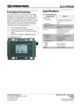
The DIN-HUB is a DIN rail-mounted Cresnet hub designed to facilitate the conguration of
large Cresnet networks. DIN rail mounting enables modular installation alongside
Crestron
®
DIN Rail lighting and automation control modules and other third-party DIN rail
mountable devices.
DIN-HUB Specications
Installation
CAUTION: This equipment is for indoor use only. Mount in a well-ventilated area. The
ambient temperature must be 32º to 104 ºF (0º to 40 ºC). The relative humidity must be
10% – 90% (noncondensing).
NOTE: Observe the following points:
• Install and use this product in accordance with appropriate electrical codes and
regulations.
• A licensed electrician should install this product.
NOTE: Before using the DIN-HUB, ensure the device is using the latest rmware. Check
for the latest rmware for the DIN-HUB at www.crestron.com/rmware. Load the
rmware onto the device using Crestron Toolbox™ software.
The DIN-HUB is designed for installation on a DIN rail. Refer to the following diagram
when installing.
1. Place the top of the DIN-HUB’s rail mount over the top of the DIN rail.
2. Tilt the bottom of the DIN-HUB toward the DIN rail until it snaps into place.
NOTE: When mounting DIN rail products, use a at-head screw driver to pull the
DIN rail release tab while snapping the device onto the DIN rail.
To remove the DIN-HUB from the DIN rail, use a small, at object (i.e., a at-head
screwdriver) to pull the DIN rail release tab, and tilt the bottom of the DIN-HUB away from
the DIN rail.
NOTE: Certain third-party DIN cabinets provide space for an informational label
between each DIN rail row. Crestron’s Engraver software (version 4.0 or later) can
generate appropriate labels for all Crestron DIN rail products.
Installing the DIN-HUB
Additional Resources
Visit the product page on the Crestron website (www.crestron.com)
for additional information and the latest rmware updates. Use a QR
reader application on your mobile device to scan the QR image.
DIN-HUB
Top
DIN rail
(not supplied)
DIN rail
release
NET HOST
NET PWR INPUT
24VDC
NET A
HOST
EXT
G
NET B
HOST
EXT
G
NET C
HOST
EXT
G
CRESNET DISTRIBUTION HUB
DIN-HUB
NET
PWR
NET C
PWR
NET
NET B
PWR
NET
NET A
PWR
NET
24 Y
Z
G
24
Y
Z
G
24 Y
Z
G
24
Y
Z
G
24YZG 24YZG 24YZG
24 Y
Z
G
NET PWR INPUT:
24 Vdc jumpered from NET HOST
port or external supply. Each port
provides power to a segment.
NET A:
Connect to Cresnet
devices on segment A
NET C:
Connect to Cresnet
devices on segment C
NET:
To control system and
other Cresnet devices
NET B:
Connect to Cresnet
devices on segment B
SPECIFICATION DETAILS
Power Requirements
Cresnet Power Usage 0.6 W (0.03 A @ 24 Vdc)
Maximum Load per Segment 75 W (3.13 A @ 24 Vdc)
Environmental
Temperature 32° to 104 °F (0° to 40 °C)
Humidity 10% to 90% RH (noncondensing)
Heat Dissipation 2 Btu/h

As of the date of manufacture, the device has been tested and found to comply with specications for
CE marking.
Federal Communications Commission (FCC) Compliance Statement
This device complies with part 15 of the FCC Rules. Operation is subject to the following
conditions:(1) This device may not cause harmful interference and (2) this device must accept any
interference received, including interference that may cause undesired operation.
CAUTION: Changes or modications not expressly approved by the manufacturer responsible for
compliance could void the user’s authority to operate the equipment.
NOTE: This equipment has been tested and found to comply with the limits for a Class B digital
device, pursuant to part 15 of the FCC Rules. These limits are designed to provide reasonable
protection against harmful interference in a residential installation. This equipment generates, uses
and can radiate radio frequency energy and, if not installed and used in accordance with the
instructions, may cause harmful interference to radio communications. However, there is no guarantee
that interference will not occur in a particular installation. If this equipment does cause harmful
interference to radio or television reception, which can be determined by turning the equipment off
and on, the user is encouraged to try to correct the interference by one or more of the following
measures:
• Reorient or relocate the receiving antenna.
• Increase the separation between the equipment and receiver.
• Connect the equipment into an outlet on a circuit different from that to which the receiver is
connected.
• Consult the dealer or an experienced radio/TV technician for help.
The product warranty can be found at www.crestron.com/warranty.
The specic patents that cover Crestron products are listed at patents.crestron.com.
Certain Crestron products contain open source software. For specic information, please visit
www.crestron.com/opensource.
Crestron, the Crestron logo, Cresnet, and Crestron Toolbox are either trademarks or registered
trademarks of Crestron Electronics, Inc. in the United States and/or other countries. Other
trademarks, registered trademarks, and trade names may be used in this document to refer to either
the entities claiming the marks and names or their products. Crestron disclaims any proprietary
interest in the marks and names of others. Crestron is not responsible for errors in typography or
photography.
This document was written by the Technical Publications department at Crestron.
©2016 Crestron Electronics, Inc.
Crestron Electronics, Inc. Installation Guide - DOC. 6671B
15 Volvo Drive Rockleigh, NJ 07647 (2020753)
Tel: 888.CRESTRON 10.16
Fax: 201.767.7576 Specications subject to
www.crestron.com change without notice.
Troubleshooting
The following table provides corrective actions for possible trouble situations. If further
assistance is required, please contact a Crestron customer service representative.
DIN-HUB Troubleshooting
To power a segment externally, connect the external power supply to the EXT and G pins
on the segment’s NET PWR INPUT port.
Powering a Hub Segment Externally (Segment A Shown)
Power can be supplied from a DIN rail power supply or other Cresnet power supply
connected to the NET HOST port.
NOTE: The DIN-HUB can only be powered by the NET HOST port. Power cannot be
supplied from network devices that are connected to any of the segments.
Hub segments can be powered internally or from an external power supply. To power a
segment internally, install a jumper from the HOST pin to the EXT pin on the segment’s
NET PWR INPUT port.
Powering a Hub Segment Internally (Segment A Shown)
NET A
HOST
EXT
G
DIN-PWS50 or
other Crestron
24 Vdc supply
NET A
HOST
EXT
G
24 G
TROUBLE POSSIBLE CAUSE(S) CORRECTIVE ACTION
The NET HOST PWR
LEDs do not light.
The DIN-HUB is not
receiving power.
Determine that the NET
HOST port on the
DIN-HUB is properly
connected to a Cresnet
power supply.
The segment’s NET LED
does not light.
The segment is improperly
wired.
Verify wiring
connections: proper
connector is used, cable
is intact, and
connections are secure.
One or more devices
attached to the segment
are not properly identied
in SIMPL Windows.
Use Crestron Toolbox to
verify that the SIMPL
Windows program
recognizes all of the
devices.
Another segment is
improperly wired.
Remove all segment
connections except for
the segment attached to
the control system and
the segment for which
the LED is not lit.
The segment’s PWR LED
does not light.
The wiring at the NET
PWR INPUT port is
incorrect.
Verify that the NET PWR
INPUT port is wired
correctly for internal or
external power.
There is insufcient
power.
Verify that sufcient
power is available. If
necessary, connect the
NET PWR INPUT port to
an external power
supply.
The network is not
working, and only one
LED lights.
There is a wiring problem. Disconnect the segment
that resulted in the lit
LED, and correct the
wiring.
/