Page is loading ...

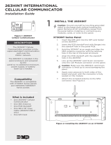
263H HSPA+ Cellular Communicator
Description
The 263H HSPA+ Cellular Communicator provides a fully-supervised alarm communication path over the HSPA+ network. The
263H is installed in the panel enclosure and powered by the panel - no additional enclosure, power supply, or battery back-up
is needed.
Installation Safety
Ground yourself before handling the panel! To discharge static, touch any grounded metal, such as the
enclosure, before touching the panel.
Remove all power from the panel! Remove all AC and battery power from the panel before installing or
connecting any modules, cards, or wires to the panel.
Installing the 263H
For XT30/XT50 Series:
1. Insert the SIM card into the 263H as pictured in Figure 1.
2. Insert the PCB standoff end with anges into the standoff hole in the panel PCB.
3. Hold the 263H at an angle and align the SMA antenna connector with the antenna hole in
the top of the panel enclosure.
4. Align the PCB standoff with the standoff hole in the 263H.
5. Line up the 263H card 12 pin connector onto the Cell Module connector on the panel.
Caution: Make sure the 263H card 12 pin connector is lined up to avoid damaging
the panel. See Figure 3 callout.
6. Apply even pressure to both sides of the board and push until the connector
is fully seated on the module. See Figure 2.
For XR150/XR550 Series:
1. Insert the SIM card into the 263H as pictured in Figure 1.
2. Insert the PCB standoff end with anges into the standoff hole in the panel PCB.
3. Align the PCB standoff with the standoff hole in the 263H.
4. Line up the 263H card 12 pin connector onto the Cell Module connector on
the panel.
Caution: Make sure the 263H card 12 pin connector is lined up to avoid damaging
the panel. There should be a space between the top of the connector and the
Ethernet port. See Figure 3 callout.
5. Apply even pressure to both sides of the board and push until the connector
is fully seated on the module. See Figure 3.
Note: If needed, the PCB can be removed from the
enclosure to allow placement of the cell module.
Connecting the Antenna
For XT30/XT50 Series:
Attach the included antenna to the SMA connector. Refer
to Figure 2.
For XR150/XR550 Series:
1. Attach the 381-2 cable to the SMA connector.
2. Position one of the washers onto the 381-2 SMA
connector and push the threaded end through an
enclosure knockout. See Figure 2.
3. Position the second washer onto the threaded end
extending through the knockout and secure the nut.
Antenna
Connector
SMA
Connector
Cellular Antenna
enclosure hole
J3
Phone Line
Outputs
J11
1
2
3
4
J1
Ethernet
J16
Reset
J20
Wireless
Antenna
connection
J7 RJ
Supervision
Figure 2: 263H Installation
(XT30/XT50)
Figure 3: 263H Installation
(XR150/XR550)
XR150/XR350/XR550
Pane
l
SMA
Connector
PCB
Standoff
263HI
Nut
Washers
SMA
Connector
Antenna
Connector
Model 381-2
Coax Cable from
the 263H module
65555
SIM
CARD
Bottom View
Figure 1: 263H SIM
Card Installation
Compatibility
• XT30/XT50 Series panels Version 112
or higher that do not contain a built-
in modem
• XR150/XR550 Series panels
Included Components
• One Model 263H
• One SIM card
• One Model 383 Rubber Duck Antenna
• One PCB standoff
INSTALLATION SHEET

Digital Monitoring Products 263H Installation Sheet
2
4. Attach the included 383 Antenna to the SMA connector.
5. Attach the opposite end of the 381-2 Coax to the SMA connector
on the 263H. See Figure 2.
Note: As an alternative, an antenna coax can be connected directly
to the 263H SMA connector when the coax enters the enclosure
via conduit.
Activating the 263H
Remote Link Activation
Cellular Service is required before using the 263H for signal
transmission. The 263H comes ready for activation with SecureCom
Wireless, LLC.
1. In Remote Link panel communication programming, select C
ellular Network as the Communication Type and select the
Activate button. See Figure 4.
2. In the Activate SIM/MEID window, enter the SIM number, found
on the SIM card.
3. Select the rate plan for the 263H. See Figure 5.
4. Select the Activate button at the bottom of the window.
Performing Diagnostics
The panels provide a Diagnostics function to test the Communication
integrity and Cellular Signal strength of the 263H. To use Diagnostics, reset the panel, enter the Diagnostics code 2313
(DIAG), and press COMMAND.
Communication Status
Select COMM STATUS from the Diagnostics menu. The panel tests the 263H for the following items:
Cellular Signal
Select CELL SIGNAL from the Diagnostics menu. The panel tests and indicates the strength of the signal using a bar display.
One bar indicates a weak signal and seven bars indicate a strong signal. The signal strength is displayed as a -dBm value.
Figure 4: Remote Link Activation
Figure 5: Remote Link Activation
• 263H Installed
• 263H Operating
• 263H Registered
• 263H Identied
• Cellular Tower Detected
• Connect Success
• Communication Path
Integration

263H Installation Sheet Digital Monitoring Products
3
FCC Information
This device complies with Part 15 of the FCC Rules. Afx the included FCC label to the exterior of the panel enclosure in
plain sight. Operation is subject to the following two conditions:
1. This device may not cause harmful interference, and
2. this device must accept any interference received, including interference that may cause undesired operation.
Changes or modications made by the user and not expressly approved by the party responsible for compliance could void
the user’s authority to operate the equipment.
Note: This equipment has been tested and found to comply with the limits for a Class B digital device, pursuant to
part 15 of the FCC Rules. These limits are designed to provide reasonable protection against harmful interference in a
residential installation. This equipment generates, uses, and can radiate radio frequency energy and, if not installed and
used in accordance with the instructions, may cause harmful interference to radio communications. However, there is no
guarantee that interference will not occur in a particular installation. If this equipment does cause harmful interference to
radio or television reception, which can be determined by turning the equipment off and on, the user is encouraged to try
to correct the interference by one or more of the following measures:
• Reorient or relocate the receiving antenna.
• Increase the separation between the equipment and receiver.
• Connect the equipment into an outlet on a circuit different from that to which the receiver is connected.
• Consult the dealer or an experienced radio/TV technician for help.
Industry Canada Information
Industry Canada Class B Statement
This Class B digital apparatus complies with Canadian ICES-003.
Cet appareil numérique de la classe B est conforme à la norme NMB-003 du Canada.
This device complies with Industry Canada Licence-exempt RSS standard(s). Operation is subject to the following two
conditions: (1) this device may not cause interference, and (2) this device must accept any interference, including
interference that may cause undesired operation of the device.
Le présent appareil est conforme aux CNR d’Industrie Canada applicables aux appareils radio exempts de licence.
L’exploitation est autorisée aux deux conditions suivantes : (1) l’appareil ne doit pas produire de brouillage, et (2)
l’utilisateur de l’appareil doit accepter tout brouillage radioélectrique subi, même si le brouillage est susceptible d’en
compromettre le fonctionnement.

INTRUSION • FIRE • ACCESS • NETWORKS
2500 North Partnership Boulevard
800-641-4282
www.dmp.com
Springeld, Missouri 65803-8877
Designed, Engineered and
Assembled in U.S.A.
LT-1270 1.03 © 2017 Digital Monitoring Products, Inc.
17032
Specications
Primary Power 12VDC from panel
Current Draw
Standby 24 mA
Alarm 28 mA
Compatibility
XT30/XT50 Series panels
XR150/XR550 Series panels
Accessories
380-40 Level 400 SecureCom SIM Card
380-400R Level 400 Rogers SIM Card
381-2 18" Coax Cable
381-12 12' Coax Extension
381-25 25' Coax Extension
383 Rubber Duck Antenna (included)
386 Outdoor Antenna Mounting Bracket
387-1 3dB Fiberglass Antenna w/Bracket
387-2 2dB Attack Enclosure Antenna
387-3 3dB MEG Antenna
Ordering Information
263H Cellular Communicator
263H/381-2 Cellular Communicator with 18"
Coax Cable
263HCAN Canadian Cellular Communicator
Certications
California State Fire Marshall (CSFM)
New York City (FDNY COA #6167)
FCC Part 15B and CISPR 22
FCC ID: RI7HE910NA
Industry Canada: 5131A-HE910NA
ANSI/UL 294 Access Control System Units
ANSI/UL 636 Holdup Alarm Units and System Accessory
ANSI/UL 1023 Household Burglar
ANSI/UL 1076 Proprietary Burglar
ANSI/UL 1610 Central Station Burglar
ANSI/UL 1635 Digital Burglar
ANSI/UL 985 Household Fire Warning
ANSI/UL 864 Fire Protective Signaling 9th Edition.
ULC S304 Central Station Burglar
ULC - Subject-C1023 Household Burglar
ULC/ORD - C1076 Proprietary Burglar
ULC - S545 Household Fire
ULC - S559 Equipment for Fire Receiving Centers
and Systems
/