Page is loading ...

BF362-5 24 V 5 A EN54-4 Boxed PSU
Installation Instructions
VdS
G209197
FIRE ALARM
ancillaries 1 of 2
Approved Document No. DFU0003611 Rev 5
THIS EQUIPMENT MUST ONLY BE INSTALLED AND MAINTAINED BY A SUITABLY SKILLED AND TECHNICALLY
COMPETENT PERSON. THE PSUSARE CLASS 1 EQUIPMENT AND MUST BE EARTHED.
BF362-5 is a boxed Mains to regulated DC power supply providing 5 A @ 24 Vdc. Combining the functions of a power
supply unit, battery charging unit and battery monitoring unit, it is fully compliant with the current edition of
EN 54-4:1997 + A1:2003 + A2:2007.
INSTALLATION
Location
The power supply must be sited indoors on a dry, flat surface in an area that is well ventilated. Ideally the panel
indicators should be at eye level and the ambient light level should allow the status of the indicators to be clearly seen.
Mounting
Using the five mounting holes provided, mount the metal base securely onto a wall. Assess the condition and
construction of the wall and use suitable screw fixings. The mounting holes are suitable for use with No.8-10 or
4-5 mm countersunk screws. Any dust or swarf created during the mounting process must be kept out of the enclosure
and care must be taken not to damage any wiring or components.
Wiring and Cable Entry
All wiring should be installed in accordance with the current edition of the IEE Wiring Regs
(BS 7671), or the relevant national standards. The requirement for the Mains supply to the
panel is fixed wiring, using 3-core cable (no less than 1 mm2and no greater than 2.5 mm2),
or a suitable three conductor system fed from an isolating switched spur fused at 3 A.
In order to maintain cable segregation the incoming Mains cable should be fed into the
panel via the top centre knockouts (provided on the metal base). Knockouts should be
removed with a sharp, light tap using a flat 6 mm broadsided screwdriver, as shown in the
diagram (see right). Always ensure that if a knockout is removed, the hole is filled with a
good quality 20 mm cable gland. Any unused knockouts must be securely blanked off.
WARNING: DO NOT ATTEMPT TO CONNECT THE MAINS SUPPLY TO THE POWER
SUPPLY PCB UNLESS ALL COMPONENTS ARE SECURELY INSTALLED IN THE ENCLOSURE.
Terminate the Mains cable at the Power Supply connector block CONN1 (see Figure 1 below).
RPF0361000 Rev2
Temp
Display
Black- Red+
BATT ERY
FUSE
F2
F5A CONN4
0V Charge
Off
C NC NO
Fault Relay
No Batteries
PLK1
PLK2
Fit for 5.5 to 18Ahr
Not fitted for 1.6 to 5.5Ahr PL2
RLY1
CONN3
Output
C10C10
++
++
CONN5
0V +V
VR1
DO NOT
ADJUST
C6C6
PL1
PL3
T2AH 250V
HRC
PRIMARY
FUSE F1
LED MUST
EXTINGUISH
BEFORE
SERVICE
C1
TX1
C11C11
D7D7
R24R24
Battery
C24C24
C20C20 C23C23
C31C31
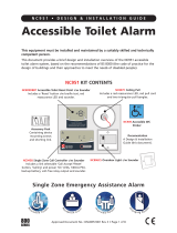
Mains Input Terminals (CONN1)
L = Live, N = Neutral, = Earth
CLASS 1 EQUIPMENT MUST BE EARTHED.
Connect incoming Mains earth wire
to the earth terminal and NOT to the
base earth post.
PSU Earth Strap
DO NOT operate this equipment
without connecting this strap to the
base earth post.
Display Connector (PL1)
High Temp. Output (PL2)
Charge Off Input (CONN4)
Incoming Mains Cable
Must be segregated from other
cables and only enter the panel
through the top central knockouts.
Hazardous Voltages Present LED
When lit red, hazardous voltages
are present on the components
and copper in the hashed area of
the PCB. DO NOT TOUCH!
Supply Output (CONN5)
Battery Input (CONN5)
Figure 1 - Power Supply PCB Layout and Connection Details
Battery Charge Current Link (PLK2)
Fault Relay (CONN3)
Battery Monitoring Link (PLK1)
If batteries NOT used, fit PLK1 link.
See Technical Specification
overleaf for further details
0786-CPD-20892

POWER SUPPLY SPECIFICATION
Mains supply voltage / Rated current / VA: 230 Vac, 50/60 Hz / 1.35 A / 310 VA
Max. continuous output current (including charging): 5 A
Battery charge capacity: 7 Ah to 18 Ah
Max VRLA battery size/type determined by cabinet size: BF360 range = up to 3 Ah (Note: BF360-12 without STU plate = 7 Ah)
(various models listed) BF361 range = 7 Ah
BF362 range = up to 18 Ah
Power rating: I max a = 4.6 A or 4.0 A (if PLK2 link fitted)
I max b = 5 A, charging turned off via CONN4 short
I min = 12 mA approx.
Maximum internal battery resistance: Ri max = 600 mohm
Maximum output voltage: V max = 30 V
Minimum output voltage at battery cut off: V min = 19.2 V
Output ripple voltage (peak-to-peak): 450 mV @ 30 MHz bandwidth, 350 mV with a 100 nF loading.
Mains supply/battery charger monitored for failure: YES
Batteries monitored for disconnection and failure: YES
FUSES
Mains supply fuse (F1): 2 A HRC, 20 mm ceramic
Battery fuse (F2): 5 A F, 20 mm glass
POWER SUPPLY PCB CONNECTIONS
Mains Input (CONN1): Three Mains supply input terminals: Live, Neutral & Earth
Fault Relay (CONN3): Isolated relay output rated 1 A @ 50 V
Charge Off Input (CONN4): Disablement of the battery charge, enabling the charge current to be used at the output during heavy load
periods, volt-free short to 0 V to disable charger. Maximum cable length = 2.5 m.
Supply Output (CONN5): 24 Vdc output for auxiliary equipment at PSU’s rated output of 5 A
Battery Input (CONN5): Connection to the VRLA batteries
PL1: 4-way connector for wiring loom from PCB to a display card, or OEM equipment, for transmission of C-TEC data protocol.
PL2: High Temperature Output. Operates at approx. 55 oC internal box temperature, 30 V, 200 mA max. current sink.
PLK1: ‘Battery Monitoring’ link. Fit link if batteries NOT used.
PLK2: ‘Battery Charge Current’ link.
Fitted for 7 Ah to 18 Ah (1 A charge).
Note: Special requests can be catered for, up to 60% of the total PSU output.
INDICATORS
Panel indicators (LEDs): SUPPLY PRESENT (Green) – Indicates the supply is present at the output.
GENERAL FAULT (Amber) – Indicates a fault is present on the PSU. Call the engineer.
AUXILIARY FAULT (Amber) – Indicates a fault with an auxiliary unit (user-definable). 19 to 30 V, 3.5 to 6 mA.
Power Supply PCB (LED): Hazardous Voltages Present (Red)
PHYSICAL ATTRIBUTES
Dimensions: 404 mm (width) x 404 mm (height) x 110 mm (depth)
Weight / Construction: 5.25 Kg (without batteries) / Metal lid and base
Enclosure finish: RAL7035 textured
ACCESSORY PACK
1 x Instructions – Document No. DFU0003611 (this document); 1 x Allen key (for unfastening/securing the panel’s lid); 1 x 2 A HRC, 20 mm ceramic
fuse (spare Mains supply fuse F1); 1 x 5 A F, 20 mm glass fuse (spare battery fuse F2); 1 x set of links for PLK1 & PLK2; 1 x battery connection kit.
OPERATING CONDITIONS
The power supply enclosures have an IP30 rating (to EN60529:1992) and are designed for indoor use only. The components are selected to operate
within their specification when the environmental conditions outside the enclosure comply with class 3k5 of the latest edition of IEC 721-3-3:1978.
Temperature range: -5 oC to +40 oC. Maximum relative humidity: 95%.
CERTIFICATION
VdS Approval No.: G209197 CE Cert. No.: 0786-CPD-20892
FIRE ALARM
ancillaries 2 of 2
Approved Document No. DFU0003611 Rev 5
Batteries
CAUTION: There is a risk of explosion if incorrect batteries
are used. Always dispose of used batteries in accordance
with the battery manufacturers instructions.
For the emergency standby power supply, only use good
quality sealed VRLA batteries. Position and connect 2 x 12 V
batteries, as shown in diagram (see right).
Note: On a standard ‘as-supplied’ unit, PLK1 (‘Battery
Monitoring’ link) is NOT fitted and a fault will occur on initial
power-up if fully charged batteries are NOT connected.
+
–
12 V BATTERY
+
–
12 V BATTERY
POWER SUPPLY
PCB
3 x battery connection
leads (supplied with
accessories)
LOCATION OF 2 x 12 V BATTERIES AND CONNECTION
OF BATTERY LEADS TO POWER SUPPLY PCB
Black- Red+
Output
CONN5
0V +V
Battery
TECHNICAL SPECIFICATION
E&OE. No responsibility can be accepted by the manufacturer or distributors of these power supplies for any misinterpretation of this instruction,
or for the compliance of the system as a whole. The manufacturers policy is one of continuous improvement and we reserve the right to make
changes to product specifications at our discretion and without prior notice.
Manufacturer: Computionics Limited (C-TEC), Stephens Way, Wigan, Lancashire WN3 6PH, England - C-TEC.co.uk
Niederlassung Deutschland: C-TEC Germany Limited, Virchowstr. 32, D-33332 Gϋtersloh -C-TEC-Germany.de
/