Page is loading ...

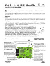
1 Pre Installation
All five circled
fixing positions
are available for
use.
The key hole can
also be used for
locating and
fixing where
required.
2 Components
Part No Product Description
!
Installation must conform to applicable local installation
codes and
should only be installed by a fully trained
competent person.
Ensure the RCC is installed as per the site survey.
Refer to step 3 to ensure optimised wireless performance.
If using remote aerials with this product, refer to the Remote
Aerial Installation guide for more information.
6 Fix to the Wall
4 Optional PCB Removal
5 Remove Cable Entry Points
Drill the cable entry
points as necessary.
Radio Cluster Communicator
POWER
FAU LT
1
2
3
4
5
= Do Not Use
= Available Cable
Entry Points
3 Mounting Location Guidelines
POWER
FAULT
0.6m
2m
Power
Supply
RCC
24Vdc Radio Cluster Communicator (RCC)
Installation Guide
RADIO CLUSTER COMMUNICATOR
POWER
FA ULT
FC-555-024
FC-555-324
24Vdc Powered RCC
24Vdc RCC c/w remote aerial facility
Ensure the RCC is not installed
within 2m of other wireless or
electrical equipment.
The RCC must not be installed
within 0.6m of any metal work.
Note: the above points exclude
the power supply, provided it is
mounted below the RCC as
shown.
Remove the three circled retaining screws, before unclipping
the PCB.
RESET
LOGONBACK
HEALTHY
FAU LT
SYS FAULT
RF1 RF2
ATTENTION
OBSERVE PRECAUTIONS
FOR HANDLING
ELECTROSTATIC
SENSITIVE
For optimum wireless
performance,the
following must be
observed:
4x Corner Covers 4x Lid Screws 1x RCC Lid
1x RCC PCB
1x RCC Box
1
2
3
4
5
©2018 EMS Ltd. All rights reserved Page 1 of 2 TSD054 Iss 8 05/09/2018 AJM

RADIO CLUSTER COMMUNICATOR
POWER
FAU LT
RESET
LOGONBACK
HEALTHY
FAULT
SYS FAULT
RF1 RF2
Figure 9
POWER 1 POWER 2
+ - + -
OK
OK
DO NOT
ADJUST VR1
L N
BATTERY FUSE
3.15AF F2
CONN4
FAULT RELAY
CONN3
CONN1
+v
Battery
0v
+v
Output
0v
PLK1
NO NCC
PLK2
PL2
Temp
PL1
Display
off
Charg
e
0v
CONN5
PRIMARY
FUSE F1
1ATH
250V
HRC
0V
+V
0V
+V
Output
Battery
CONN3
CN/CN/O
CONN4
Fault
RESET
LOGONBACK
HEALTHY
FAU LT
SYS FAULT
RF1 RF2
Figure 9
POWER 1 POWER 2
+ - + -
OK
OK
9 Configuration
The RCC’s programming and loop address are configured within
the menu structure of the Radio Hub.
TX
RESET
RX
HEALTHY
FA U LT
SYS
FA U LT
LOOP 1
+
-
IN OUT IN OUT
+
-
LOOP 2
+
-
IN OUT IN OUT
+
-
RF1 RF2
8 Applying Power
Apply power to the power supply. The normal LED states for the
RCC are as below:
10 Close RCC
Ensure that the RCC PCB is correctly inserted and the PCB
retaining screws are refitted.
Refit the RCC lid, ensuring LEDs are not damaged by the light
pipe when refitting.
Healthy LED - Green LED will be on.
Fault LED - Yellow LED will be off.
Sys Fault LED - Yellow LED will be off.
Power 1 LED - Green LED will be on.
Power 2 LED - Green LED will be on.
7 Connection Wiring
Power cables should only be passed via the access points
available.
Flame retardant cable glands should be used.
DO NOT leave excess cable in the RCC.
RADIO CLUSTER COMMUNICATOR
POWER
FAU LT
Operating
Temperature -10°C to 55°C
Storage
Temperature 5°C to 30°C
Humidity Up to 95% non-condensing
IP Rating IP54
Operating Voltage 17 to 28Vdc
Power Requirements 17mA @ 24Vdc
Operating Frequency 868MHz
Output Transmitter
Power Auto adjusting 0 - 14 dBm (0 - 25 mW)
Dimensions 270mm (W) 205mm (H) 75mm (D)
Weight 0.95kg
Application Indoor use only
2012/19/EU (WEEE directive):
Products marked with this symbol cannot be
disposed of as unsorted municipal waste in the
European Union. For proper recycling, return this
product to your local supplier upon purchase of
equivalent new equipment, or dispose of it at
designated collection points. For more information
see www.recyclethis.info
Certification
Certification body
CPR Certificate DOP 0359-CPR-0046
Approved to
EN54-18:2005. Fire detection and fire alarm
systems. Part 18: Input/output devices.
EN54-25:2008. Incorporating corrigenda September
2010 and March 2012. Fire detection and fire alarm
systems. Part 25: Components using radio links.
European Union
directives
Refer to the programming manual (Doc Ref: MK98) for full
programming information.
0359
Free to download from
www.emsgroup.co.uk
12
Regulatory InformationSpecification
Manufacturer EMS Ltd. Technology House, Herne Bay, Kent,
CT6 8JZ, United Kingdom
Year of manufacture See devices serial number label
EMS declares that the radio equipment type FireCell
24Vdc RCC is in compliance with Directive
2014/53/EU. The full text of the EU declaration of
conformity is available at the following internet
address: www.emsgroup.co.uk
©2018 EMS Ltd. All rights reserved Page 2 of 2 TSD054 Iss 8 05/09/2018 AJM
/