Page is loading ...

XFP
32 ZONE
REPEATER
PANEL
installation
manual
approved document no. DFU2200502 Rev 1

CONTENTS
Important Notes ....................................................................................................................3
Basic Overview & Key features ............................................................................................4
Installation and wiring ........................................................................................................4
The fire panel enclosure ..................................................................................................................................4
Removing the lid and base PCBs......................................................................................................................4
Mounting the base to the wall........................................................................................................................5
Planning the cable layout in the panel ..........................................................................................................5
Mains wiring......................................................................................................................................................6
Connecting mains to the Power Supply PCB ..................................................................................................6
Installing the standby battery supply ..............................................................................................................7
Fault relay output wiring ................................................................................................................................7
Repeater network wiring ................................................................................................................................7
Technical specifications ........................................................................................................8
Disclaimer
©2005-2007. No responsibility can be accepted by the manufacturer or distributors of this range of
fire panels for any misinterpretation of an instruction or guidance note or for the compliance of the
system as a whole. The manufacturer’s policy is one of continuous improvement and we reserve the
right to make changes to product specifications at our discretion and without prior notice. E&OE.
XFP ENGINEERING MANUAL • Approved Document No. DFU2200502 Rev 1 • Page 2 of 8
XFP 32 ZONE REPEATER PANEL
This product has been manufactured in conformance with the requirements of all
applicable EU Council Directives.
Please refer to the Installation & Maintenance Manual and User Guide / Log Book
supplied with the main XFP panel for details of the repeater’s indicators, controls and
programming options.

IMPORTANT NOTES
This equipment must only be installed and maintained by a suitably skilled
and technically competent person.
This equipment is a piece of Class 1 equipment and MUST BE EARTHED.
ALWAYS isolate the panel’s mains and battery backup supplies before making
connections to its PCBs.
Items supplied with this panel
•Installation manual - document no. DFU2200502 (this manual)
• Hex key, for unfastening / securing the panel lid
• Electrical accessory pack, containing:-
1x20mm 1ATH 250V HRC ceramic fuse (spare primary fuse)
1xbattery jumper link wire
System design
Fire alarm system design is beyond the scope of this document. A basic understanding of general
fire alarm system components and their use is assumed.
Contact the Fire Officer concerned with the property at an early stage in case he has any
special requirements. Westrongly recommend that a suitably qualified and competent person
is consulted in connection with the design of the fire alarm system and that the system is
commissioned and serviced in accordance with the laid down specification and national
standards. If in doubt please consult your supplier.
Werecommend you read BS 5839: Pt 1: 2002 "Fire Detection and Alarm Systems for Buildings
(Code of Practice for System Design, Installation, Commissioning and Maintenance)" available at
your local reference library or from the BSI. Other national standards of installation should be
referenced where applicable.
Cable types and limitations
All system wiring should be installed to meet current national standards - in the United Kingdom
these are BS 5839 pt 1 : 2002 and BS7671 (Wiring Regulations).
1.5mm2two-core fire resistant screened cable should be used throughout the repeater network
installation. This not only shields the data moving up and down the cables from outside interference
but is essential to ensure compliance with EMC regulations. Cables such as FP 200, Firetuff™,
Firecel™ and MICC may be acceptable provided they are properly terminated at the fire panel and
meet national standards / the system specification as applicable. Consult Clause 26 of BS 5839 pt 1 :
2002 for more detailed information on cables, wiring and other interconnections.
Equipment guarantee
This equipment is not guaranteed unless the complete installation is installed and commissioned
in accordance with the laid down national standards (in the UK BS 5839: Pt 1: 2002) by an
approved and competent person or organisation.
Anti-static handling guidelines
Always observe appropriate electro-static handling precautions prior to handling the
panel’sPCBs or any other static-sensitive components.
XFP ENGINEERING MANUAL • Approved Document No. DFU2200502 Rev 1 • Page 3 of 8
XFP 32 ZONE REPEATER PANEL

INSTALLATION & WIRING
The fire panel enclosure
The panel is supplied with a hinged metal lid, metal back box and five separate PCBs (a Main Control
PCB, a Power Supply PCB, a Network Communication Card, a Switch & Indicator PCB and an LCD PCB.
Space is available inside the panel for the rated capacity of VRSLA backup batteries.
The panel must be sited internally in an area that is not subject to conditions that are likely to affect its
performance, e.g. damp, salt-air, water ingress, extremes of temperature, physical abuse, etc. It should
be sited at a height whereit is easily accessible and in a prominent position within the building.
Ideally, its front panel indicators should be at eye level.
Typical locations for the panel arein the entrance foyer/hallway at ground floor level (the first and
most obvious point of contact for emergency services) or a permanently manned security office.
It is recommended that you remove the panel’s lid and base PCBs prior to first fix installation to
protect the electronics from damage.
Removing the lid and base PCBs
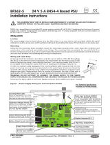
Fig. 1 : Location of the panel’s base PCBs and removal details
To remove the lid: -
•Take the panel out of its box and undo the two lid screws using the hex key provided.
•Hinge the lid 180° to the left (do not overbend the hinges) and remove the lid earth strap’s spade
connector.
•Disconnect the telecoms-style lid/base connecting cable from PL5 on the Main Control PCB. Care
should be taken when detaching the connector to depress the locking tab to prevent damage.
XFP ENGINEERING MANUAL • Approved Document No. DFU2200502 Rev 1 • Page 4 of 8
XFP 32 ZONE REPEATER PANEL
LCD PCB
SWITCH & INDICATOR PCB
MAIN
CONTROL
PCB
POWER
SUPPLY
PCB
LID EARTH STRAP
TWO-WAYLID/BASE
CONNECTOR CABLE
TELECOMS-STYLE LID/BASE
CONNECTOR CABLE
PL1
POWER SUPPLY PCB
EARTH STRAP
TEN-WAY PSU
CONNECTOR CABLE
PCB RETAINING
SCREW
PCB RETAINING
SCREW
BASIC OVERVIEW & KEY FEATURES
Amaximum of eight XFP Repeaters (any mix) can be connected to one non-networked XFP main panel
(note that the main panel’s Network Comms function must be set to Repeater mode).
Each Repeater requires its own dedicated mains power and battery back-up supply.
Communication between the main panel and repeaters is achieved using network communication
cards - one per repeater (fitted as standard) and one per main (available as an optional extra), wired in
1.5mm2two-core screened fire resistant cable. The total network length for a repeater network must
not exceed 500m.
Each repeater offers all the functions and controls of an XFP main panel (access levels 1, 2 and 3).
Repeaters do not include an RS232 PC programming connector. System programming must be carried
out at the XFP main panel using the panel’s upload/download programming tools and a Windows PC.
Please refer to the XFP main panel instructions for details.
Afault relay is included in all repeaters.
NET. COMM CARD
PL5
PL4

XFP ENGINEERING MANUAL • Approved Document No. DFU2200502 Rev 1 • Page 5 of 8
XFP 32 ZONE REPEATER PANEL
•Disconnect the two-way lid/base connecting cable from PL4 on the Main Control PCB.
•Carefully remove the four M4 retaining nuts that secure the hinges and lift off the lid.
To remove the base PCBs: -
•Ensure power has been removed from the panel and that the power supply PCB is safe to handle.
•Disconnect the Power Supply PCB connecting cable from PL1 on the Main Control PCB.
•Pull the Power Supply PCB’s earth strap off the spade connector at the main base earth point.
•Carefully undo the PCB retaining screw located at the bottom left hand side of the relevant PCB
using a crosshead screwdriver.
•Slide the PCBs up and over the mounting pillars taking care not to damage any of the compo-
nents.
• Store the PCBs in a clean, dry place which is free from vibration, dust and excessive heat.
Retaining the PCBs in a suitable cardboard box will also guard them against mechanical damage.
Mounting the base to the wall
The panel can be surface or semi-flush mounted using the five mounting holes provided (note that an
optional bezel, part no. AFP735, is available for semi-flush mounting).
To expose the mounting holes you must first remove the panel’s lid and base PCBs, as described on page 5.
The mounting holes are suitable for use with No.8 roundhead or countersunk screws.
Always assess the condition and construction of the wall and use a suitable screw fixing. Any dust or swarf
created during the fixing process must be kept out of base.
Fig. 2 : Location of mounting holes and knockouts / side view of panel for flush mounting
These two
knockouts are
reserved for
incoming mains
cable only
60mm
includes
dimples
WALL
Planning the cable layout in the panel
All cables should be brought into the panel via the knockouts provided.
Note that the network cabling is classed as low voltage and must be segre-
gated away from Mains voltages. Careful planning is needed to ensure this
(see Fig. 2, above, for guidance).
Leave sufficient tails inside the panel to ensure straightforward connection
of the field wiring to the panel’s terminals. Knockouts should be removed
with a sharp, light tap using a flat 6mm broad-bladed screwdriver as shown
in the diagram (right).
Always ensureif a knockout is removed, the hole is filled with a good quality
20mm cable gland. Any unused knockouts must be securely blanked off.

Mains wiring
The requirement for the mains supply to the fire panel is fixed wiring, using three core cable (no less
than 1mm2and no more than 2.5mm2) or a suitable three conductor system, fed from an isolating
switched fused spur, fused at 3A. This should be secure from unauthorised operation and be marked ‘FIRE
ALARM: DO NOT SWITCH OFF’. The mains supply must be exclusive to the fire panel.
(As an alternative to a switched fused
spur, a double pole isolating device may
be used (see diagram below) providing it
meets the appropriate national wiring
regulations).
0.75mm < 2.5mm
FIRE
PANEL
MAIN
DISTRIBUTION
BOARD
3A
3mm
22
>1mm2<2.5mm2
Connecting mains to the Power Supply PCB
The panel’s PSU is a 185-265Va.c. 50-60Hz off line switched mode power supply that combines the
functions of a power supply unit, battery charging unit, battery monitoring unit and earth fault
monitoring unit. It should be positioned in the panel’s enclosure as shown in Fig. 3 below. DO NOT
operate the panel without the Power Supply PCB correctly mounted in the enclosure with its three
PCB retaining screws securely tightened.
DO NOT
connect mains to the Power Supply PCB until the installation is complete and ALL relevant PCBs
are correctly attached within the panel.
Fig. 3 : Power Supply PCB layout and Mains connection details
Incoming Mains cable must be segre-
gated from other cables and should
only enter the panel through either of
these knockouts. Good quality cable
glands must always be fitted.
The PSU earth strap MUST
be connected to the spade
on the main base earth
post before operation. The spade
is compressed against a shoulder on
the post via the lowest nut. The
earth post may appear loose, this is
intended by design.
WHEN CONNECTED, THE PCB STORES
VOLTAGES AT UP TO 400Vd.c. AND
MAYBE LETHAL IF TOUCHED.
DO NOT TOUCH THE PCB WHILST THE RED
‘HAZARDOUS VOLTAGES PRESENT’ LED IS LIT.
Ten-way
connection loom
(connects to PL1 on the
Main Control PCB).
DO NOT REMOVE
WHEN PANEL IS
POWERED
The incoming
mains earth
wireMUST be
connected to
the terminal
marked and
NOT to the main
base earth post.
(The PSU earth
strap connects the
PCB to the base
earth post).
XFP ENGINEERING MANUAL • Approved Document No. DFU2200502 Rev 1 • Page 6 of 8
XFP 32 ZONE REPEATER PANEL
Battery one-shot button
Pressing this button for 2-3 secs
allows authorised maintenance
personnel to power up the
system from batteries without
connecting mains.
Battery leads (note that
abattery jumper lead is
supplied in the panel’s
accessory pack). See page
7for further details.
Primary fuse (F1)
20mm 1ATH 250V
HRC ceramic fuse
to IEC 127
(EN60127-2).
Batteryfuse (F2)
20mm x 3AF
glass fuse to
IEC 127
(EN60127-2).

XFP ENGINEERING MANUAL • Approved Document No. DFU2200502 Rev 1 • Page 7 of 8
XFP 32 ZONE REPEATER PANEL
Installing the standby battery supply
Two new, good quality and fully charged 12V 3.2A Hr valve regulated lead acid batteries are required
as the emergency stand-by power supply for the panel. The batteries should be connected in series
and located in the panel’s enclosure as shown in Fig. 4 .
The battery leads, link wire and nylon cable ties are provided in the panel’s accessory pack.
The panel’s sophisticated battery monitoring unit protects the batteries against deep discharge by acti-
vating a cut off circuit when the stand-by supply voltage reaches 21V approx. If batteries are not fit-
ted, are discharged or in poor condition, a PSU fault will show at the panel.
Always dispose of used batteries according to the battery manufacturer’s instructions.
Fault relay output wiring
The repeater’s failsafe fault relay output switches for any fault condition and is
capable of switching 1A @ 30Vdc. It must NOT be used for switching mains voltages.
GENERAL
FIRE ZONE 1 ZONE 2 ZONE 3 ZONE 4 ZONE 5 ZONE 6 Z
ZONE 9 ZONE 10 ZONE 11 ZONE12 ZONE 13 ZONE 14 Z
D45
SUPPLY
PRESENT TEST ACCESSED
GENERAL
DISABLEMENT
PHASED
EVACUATION
GENERAL
FAULT
PSU
FAULT
SYSTEM
FAULT
SOUNDER
STATUS
DELA
RUNNING
Auxilliary
+24V I/P1 I/P2 0v
Relay 1
NC C NO
Relay 2
NC C NO
Relay 3
NC C NO
Fault
NC C NO
Sounder Circuits
+1- +2
REMOVING THIS CIRCUIT
BOARD EXPOSES HAZARDOUS
VOLTAGES - PLEASE REFER TO
INSTALLATION INSTRUCTIONS
WARNING
SENSITIVE TO STATIC
ELECTRICITY - OBSERVE
PRECAUTIONS BEFORE
HANDLING
CAUTION - RISK OF EXPLOSION IF
INCORRECT TYPE OF BATTERIES FITTED.
DISPOSE OF USED BATTERIES ACCORDING
TO THE MANUFACTURERS INSTRUCTIONS.
Mute
Beeper
43
Repeater network wiring
The repeater network should be wired in two-core 1.5mm2fire resistant screened cable.
Fig. 5: Typical repeater network wiring
At ONE panel only (repeater or
main), connect A to A,
Bto B and terminate incoming
and outgoing earth screens to
the panel’sside earth post.
This earth post must also be
connected to terminal C on the
network communication card’s
connector block as shown.
IMPORTANT: At all other panels,
connect A to A, B to B and
terminate earth screens to
terminal C only.
TO NEXT
REPEATER
PANEL IF
REQUIRED
NETWORK
COMMUNICATION
CARD
NETWORK
COMMUNICATION
CARD
REPEATER 1 MASTER REPEATER 2 REPEATER 5 REPEATER 8
SPUR WIRING
NOT ALLOWED
SPUR WIRING
NOT ALLOWED
=
XFP
MAIN
XFP
REPEATER
XFP
REPEATER
XFP
REPEATER
XFP
REPEATER
Fig. 4 : Battery location and connection details
TO NEXT
REPEATER
PANEL IF
REQUIRED
Red wire from panel
Shorting link (supplied in panel accessory pack)
Black wire from panel
12V battery
–
–
12V battery
+
+

XFP ENGINEERING MANUAL • Approved Document No. DFU2200502 Rev 1 • Page 8 of 8
XFP 32 ZONE REPEATER PANEL
TECHNICAL SPECIFICATION
Mains supply voltage: 230V a.c. ± 10% 50/60Hz
Internal power supply: 27V d.c Nominal
Total output current limited to: 3A @ 230V a.c.
Supply and battery charger monitored for failure: Yes
Batteries monitored for disconnection and failure: Yes
Batteries protected against deep discharge: Yes
Max. battery size and type: 3.2 AHr VRLA
Temperature compensated charging: Yes
Mains fuse: 1A HRC Ceramic 20mm
Battery fuse: 3A F 20mm
Physical dimensions: 410 x 250 x 80mm (back box); 439 x 274 x 7mm (lid)
Approx weight: 4.5kg (without batteries)
Cabling requirements: 1.5mm2two core fire resistant, screened
Max. no. of repeaters: 8
Max. cable length per repeater network: 500m
/