EUfire NC951 Design & Installation Manual
- Type
- Design & Installation Manual
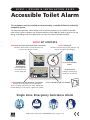
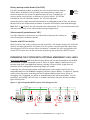
EUfire NC951 is a single zone emergency assistance alarm designed for use in accessible toilets. It consists of a ceiling pull, overdoor light, reset point, and call controller. The system is designed to be compliant with BS 8300, the code of practice for the design of buildings and their approaches to meet the needs of disabled people.
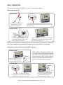
The ceiling pull is located within reach of the toilet and wheelchair, and features a red reassurance LED, red pull cord, and two triangular pull bangles. When the pull cord is activated, the overdoor light will illuminate and the call controller will sound an alarm. The reset point is located outside the toilet in a remote staffed area, and features a ‘Reset’ button with braille text, red reassurance LED, and sounder. Pressing the ‘Reset’ button will cancel the alarm and return the system to its normal state.
EUfire NC951 is a single zone emergency assistance alarm designed for use in accessible toilets. It consists of a ceiling pull, overdoor light, reset point, and call controller. The system is designed to be compliant with BS 8300, the code of practice for the design of buildings and their approaches to meet the needs of disabled people.
The ceiling pull is located within reach of the toilet and wheelchair, and features a red reassurance LED, red pull cord, and two triangular pull bangles. When the pull cord is activated, the overdoor light will illuminate and the call controller will sound an alarm. The reset point is located outside the toilet in a remote staffed area, and features a ‘Reset’ button with braille text, red reassurance LED, and sounder. Pressing the ‘Reset’ button will cancel the alarm and return the system to its normal state.


-
 1
1
-
 2
2
-
 3
3
-
 4
4
-
 5
5
-
 6
6
-
 7
7
-
 8
8


EUfire NC951 Design & Installation Manual
- Type
- Design & Installation Manual
EUfire NC951 is a single zone emergency assistance alarm designed for use in accessible toilets. It consists of a ceiling pull, overdoor light, reset point, and call controller. The system is designed to be compliant with BS 8300, the code of practice for the design of buildings and their approaches to meet the needs of disabled people.
The ceiling pull is located within reach of the toilet and wheelchair, and features a red reassurance LED, red pull cord, and two triangular pull bangles. When the pull cord is activated, the overdoor light will illuminate and the call controller will sound an alarm. The reset point is located outside the toilet in a remote staffed area, and features a ‘Reset’ button with braille text, red reassurance LED, and sounder. Pressing the ‘Reset’ button will cancel the alarm and return the system to its normal state.
Ask a question and I''ll find the answer in the document
Finding information in a document is now easier with AI
Other documents
-
Baldwin Boxall CPS Operating instructions
-
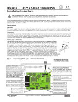 C-TEC BF362-5 Installation guide
-
ADEMCO LST700 Series Specification
-
Protec EVC40 Commissioning Manual
-
Zeta NPAD Installation guide
-
-
-
-
-
Zeta SP-126 Installation guide
