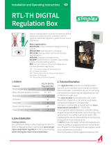
Installation and operating instructions
WRS-K
KLM air handling and ventilation module
BMK programming module
BMF remote control unit
(Translation of the original)
WOLF GMBH / POSTFACH 1380 / D-84048 MAINBURG / TEL. +49(0) 87 51 74- 0 / FAX +49(0)87 51 74- 16 00 / www.WOLF.eu
Part no.: 3062878_201707 Subjecttotechnicalmodications
GB

2
3062878_201707
Contents
1. Information about this document ............................................................5
1.1 Other applicable documents...................................................................................... 5
1.2 Safekeeping of these documents .............................................................................. 5
1.3 Applicability of these instructions ............................................................................ 5
1.4 Handover to the user .................................................................................................. 5
2. Safety and regulations .......................................................................... 6-7
2.1 Standards / directives................................................................................................. 6
2.2 Layout of warnings ..................................................................................................... 6
2.3 Symbols and warnings ............................................................................................... 7
2.4 Installation / commissioning...................................................................................... 7
2.5 CE designation ............................................................................................................ 7
3. Service / disposal ......................................................................................8
3.1 Service / repair / cleaning........................................................................................... 8
3.2 Disposal ....................................................................................................................... 8
4. Appliance description ...............................................................................9
5. Overview of KLM air handling and ventilation module ........................10
6. Installation / electrical connection of BMK programming module .....11
6.1 Wall mounted installation ........................................................................................ 11
7. Overview of BMK programming module ...............................................12
8. BMK standard display ....................................................................... 13-14
9. Operating level 1................................................................................ 15-22
9.1 Menu structure .......................................................................................................... 15
9.2 Operating data........................................................................................................... 16
9.3 Main menu ............................................................................................................16-22
9.3.1 Standard settings .........................................................................................16-20
Set temperature for manual mode .................................................................... 16
Fan stage / fan enable for manual mode .......................................................... 16
Fan speed for manual mode ............................................................................. 17
Pressure for manual mode ................................................................................ 17
Flow rate for manual mode ............................................................................... 17
Fresh air proportion for manual mode ............................................................... 17
Speed for external demand ............................................................................... 17
Pressure for external demand ........................................................................... 17
Flow rate for external demand .......................................................................... 18
Automatic start via external demand ................................................................. 18
Set humidity level .............................................................................................. 18
7-day program operating mode ......................................................................... 18
Enabling / disabling backup mode - heating ..................................................... 18
Enabling / disabling backup mode - cooling ...................................................... 18
Mixed air dampers operating mode................................................................... 19
Enabling / disabling natural cooling................................................................... 19
Enabling / disabling night ventilation ................................................................. 19
Extension of utilisation time............................................................................... 19
Peak ventilation ................................................................................................. 19
Air quality control............................................................................................... 19

3
3062878_201707
Contents
Hygrostat function ............................................................................................. 20
Continuous hygrostat function........................................................................... 20
Quick heating function....................................................................................... 20
9.3.2 Displays............................................................................................................. 21
Sensors ............................................................................................................. 21
Components ...................................................................................................... 21
Hours run .......................................................................................................... 22
Others ............................................................................................................... 22
9.3.3 Time functions ................................................................................................... 22
Seven-day program........................................................................................... 22
Day program ..................................................................................................... 23
Set values ......................................................................................................... 23
Holiday program ................................................................................................ 23
Date/time ........................................................................................................... 23
10. Operating level 2.............................................................................. 24-45
10.1 Menu structure ................................................................................................... 24-25
10.2 Heating contractor menu ....................................................................................... 26
10.2.1 Alarm management.....................................................................................26-28
Filter monitor ..................................................................................................... 27
Frost protection ................................................................................................. 27
Airowmonitor ................................................................................................. 28
Alarm memory ................................................................................................... 28
10.2.2 Service ........................................................................................................28-29
Hours run .......................................................................................................... 28
Sensor adjustment ............................................................................................ 29
Manual mode .................................................................................................... 29
Digital inputs...................................................................................................... 29
10.2.3 Backup mode ................................................................................................... 30
10.2.4 Night ventilation ............................................................................................... 31
10.2.5 Limits ............................................................................................................... 32
10.2.6 Heat generation ..........................................................................................32-33
10.2.7 Pump control.................................................................................................... 34
10.2.8 Air dampers.................................................................................................35-36
10.2.9 Cooling........................................................................................................37-38
10.2.10 Compensation................................................................................................ 39
10.2.11 Temperature control ..................................................................................40-41
10.2.12 Extension time ............................................................................................... 42
10.2.13 Peak ventilation ............................................................................................. 42
10.2.14 Air quality ....................................................................................................... 43
10.2.15Pressure/owrate ........................................................................................ 44
10.2.16 Humidity control ........................................................................................ 45-46
10.2.17 Ice guard ........................................................................................................ 47
10.2.18 Other... ...................................................................................................... 48-49
11. BMK-F remote control unit ............................................................. 50-51
11.1 Overview .................................................................................................................. 50
11.2 Standard display ..................................................................................................... 51
12. External demand....................................................................................52
12.1 Room temperature sensor with set value transducer ......................................... 52
12.2 External enabling / stage demand ......................................................................... 52

4
3062878_201707
Contents
13.Specication .................................................................................... 53-57
13.1 KLM air handling and ventilation module............................................................. 53
13.2 KLM-E extension module ....................................................................................... 54
13.3 BMK programming module .................................................................................... 54
13.4 BMK-F remote control unit..................................................................................... 55
13.5 Room temperature sensor with set value transducer ......................................... 55
13.6 NTC sensor resistances ......................................................................................... 56
13.7 h, x diagram ............................................................................................................. 57
14. Fault messages................................................................................ 58-61
15. Keyword index ................................................................................. 62-63

5
3062878_201707
1. Information about this document
1.1 Other applicable
documents
Operating instructions for the KLM air handling and ventilation module and
BMK programming module
The instructions for all accessory modules and further accessories may also
apply.
1.2 Safekeeping of these
documents
The system user or operator should ensure the safekeeping of all instruction
manuals.
f Pass on these operating instructions as well as all other applicable
manuals to the system user.
These operating instructions apply to the Wolf KLM air handling and
ventilation module, to the BMK programming module and to the BMK-F
remote control.
1.3 Applicability of these
instructions
The user of the control unit for air handling and ventilation systems
must be given instruction concerning the handling and functioning of the
control unit.
f Pass on all accompanying documents to the system user.
f Make the system user aware that the instructions should be stored near
the appliance.
f Make the system user aware that they should hand over the applicable
documents to the next user (e.g. when moving).
Instructions on the control unit for air handling and ventilation
systems
f Point out to the plant user how he can adjust the control unit to meet his
requirements in an energy saving manner.
f Instruct the system operator/user about maintenance of the air handling
and ventilation systems.
1.4 Handover to the user

6
3062878_201707
EC Directives:
- 2006/95/EC Low Voltage Directive
- 2004/108/EC EMC Directive
2.1. Standards / Directives
You will recognise warnings in these instructions by a pictogram with a line
above and below it. These warnings are laid out as follows:
Keyword
Type and source of risk.
Explanation of the risk.
f Action to prevent the risk.
2.2 Layout of warnings
EN Standards:
KLM air handling and ventilation module
- EN 55014-1
- EN 55014-2 +EC/A1/A2/IS1
- EN 60730-1 +A1/A2/A12/A13/A14/A16/EC
- EN 60730-2-9 +A1/A2/A11/A12
- EN 61000-3-2
- EN 61000-3-3 + A1/A2/IS1
- EN 61000-6-1
- EN 61000-6-2 +EC/IS1
- EN 61000-6-3
- EN 61000-6-4
- EN 61010-1
KLM-E extension module
- EN 55014-1
- EN 55014-2
- EN 60730-1
- EN 60730-2-9
- EN 61000-3-2
- EN 61000-3-3
- EN 61000-6-2
- EN 61000-6-4
- EN 61010-1
BMK programming module
- EN 55014-1 +A1
- EN 55014-2 +A1
- EN 55022 +A1
- EN 55024
- EN 61000-3-2
- EN 61000-3-3 +A1
- EN 61000-6-4
- EN 61326-1 +A1/A2
BMK-F remote control
- EN 55014-1 +A1/A2
- EN 55022 +A1
- EN 55024
- EN 60730-1
- EN 60950-1
- EN 61000-6-1
- EN 61000-6-2
- EN 61000-6-3 +A11
- EN 61000-6-4
- EN 61000-6-1
- EN 61010-1
- EN 61326-1 +A1/A2/A3
2. Safety and regulations

7
3062878_201707
2. Safety and regulations
2.4 Installation /
commissioning
- AccordingtoEN50110-1,onlyqualiedelectriciansmaycarryout
the installation and commissioning of the air handling control unit and
connected accessories.
- Observe all regulations stipulated by your local power supply utility and all
VDE or local regulations.
- DIN VDE 0100 Regulations regarding the installation of high voltage
systems up to 1000 V
- DIN VDE 0105-100 Operation of electrical installations
Where the system is not commissioned by Wolf, check all inputs and outputs
for correct wiring and function. For example:
- frost protection function
- fan rotational direction
- outdoor air dampers rotational direction
- plausibility of sensor values
- checking motor currents
- overload relay (thermal contacts / positor)
- airowmonitor
- ltermonitor
- function of heat recovery dampers (rotational direction)
- mixer air dampers (rotational direction)
- actuators, heating / cooling
- heating circuit pump / cooling circuit pump
- aswellasallothersystem-specicfunctions
The Wolf warranty will be void if the function test is not carried out correctly.
Danger due to live electrical components.
Please note: Turn off the ON/OFF switch before removing the casing.
Never touch electrical components or contacts when the ON/OFF switch is
in the ON position. This carries a risk of electrocution that could lead to injury
or death.
The supply terminals are 'live' even when the ON/OFF switch is in the OFF
position.
"Safety instructions" are instructions with which you must comply exactly, to
prevent risks and injuries to individuals and material losses.
The following symbols are used in these instructions. This important
information concerns personal as well as operational safety.
2.3 Symbols and warnings
"Please note" indicates technical instructions that must be observed to
prevent material losses and appliance malfunctions.
Please note
WiththeCEdesignation,wethemanufacturersconrmthattheair
handling control unit complies with the basic requirements of the directive
on electromagnetic compatibility (Council Directive 2004/108/EEC). The
air handling control unit complies with the basic requirements of the Low
Voltage Directive (Council Directive 2006/95/EEC).
2.5 CE designation

8
3062878_201707
Please note
3. Service / Disposal
3.2 Disposal
Appliance
At the end of its service life, the control unit should not be disposed of in
household waste.
f Ensure that the control unit and any accessories used are disposed of
properly.
Packaging
f Ensure that the packaging of the control unit and of any accessories used is
disposed of correctly.
− Regularly check the perfect function of all electrical equipment.
− Onlyqualiedpersonnelmayremovefaultsorrepairdamage.
− Only replace faulty components or equipment with original Wolf spare
parts.
− Speciedelectricalfuseratingsmustbeobserved(seetechnical
documentation). Any damage or loss resulting from technical
modicationstoWolfcontrolunitsisexcludedfromourwarranty.
− Do not use any type of cleaning product when cleaning. Please just wipe
clean with a damp cloth.
3.1 Service / repair
/ cleaning

9
3062878_201707
- Removing, bypassing or disabling of safety and monitoring equipment is
not permissible.
- The system must only be operated if it is in perfect technical condition.
Ensurethatanyfaultsordamagethatmayimpactonsafetyarerectied
immediately.
f Intended use
The Wolf KLM air handling and ventilation module is designed exclusively for
use in conjunction with Wolf appliances and Wolf accessories.
The Wolf KLM air handling and ventilation module is designed for the control
of air handling and ventilation systems.
It is normally matched to the system at the factory.
The BMK air handling programming module is designed for display and
operation of the KLM-XL air handling and ventilation module. The BMK is
available for mounting into the front of control panel doors (part no. 2744742)
and for wall mounting (part no. 2744743). Up to 2 programming modules can
be connected to one control unit.
The BMK- F remote control unit (part no. 2744751) is designed to start/
stop the system and to correct the fan speed, temperature and the fresh air
proportion. Furthermore, utilisation time extension and peak ventilation may
be activated. System faults are displayed on the remote control unit.
f Improper use
Any use other than the intended use is not permissible. Any other use or
changestotheproductatanytimeincludingduringttingandinstallation
invalidate all warranty claims. The user has sole liability for such use.
This appliance is not designed to be used by persons (including children)
withlimitedphysical,sensoryormentalcapabilitiesorwithinsufcient
experience and/or knowledge, unless they are supervised by someone
responsible for their safety or instructed by that person in the use of the
appliance.
4. Appliance description

10
3062878_201707
5. Overview of KLM air handling
and ventilation module
Assignment of KLM air handling and ventilation module
1 Power supply for control unit
2 Supply for additional programming unit (+Vterm); ratiometric 0…5 V
sensor (+5 VREF)
3 Universal inputs/outputs
4 Power supply for active sensors (+VDC)
5 Display
6 Power supply for opto-isolated analogue outputs
7 Analogue outputs
8 ID: digital inputs 24 V AC or 28 .. 36 V DC
9 ID: digital inputs 24 V AC or 28 .. 36 V DC
IDH: digital inputs 230 V AC – 50/60 Hz
10 Plug-in connection for BMK programming unit
11 Plug-in connection for BMK-F remote control (pLAN)
12 Spare
13 Spare
14 Spare
19 Plug-in connection for a KLM-E extension module

11
3062878_201707
6. Installation / Electrical connection,
programming module
6.1 Wall mounted
installation
(A)
(B)
(C)
(D)
(E)
(F)
To mount the programming module on the wall, proceed as follows:
1. Mount the wall mounting base on the wall using screws (A).
2. Install the cable and secure using the strain relief (B) supplied.
3. Guide the ends of the cable through aperture (C) in the back panel of the
programming module.
4. Secure the back panel to the wall mounting base using screws (D).
5. Connect the cable as follows:
VL / GND
+ -
Supply voltage
via KLM control unit
(see wiring diagram)
Databus (pLAN)
Tx+/Rx+
Databus (pLAN)
Tx-/Rx-
6. Secure the programming module to the back panel using screws (E).
7. Fit the cover (F; clicks into place).

12
3062878_201707
7. Overview of BMK, programming module
1 Displaying and acknowledging active fault messages
2 Displaying the system operating data (set / actual values)
3 Access to the main menu
4 Forward scrolling within a menu and increasing values
5 Switchingthesystemonandoff,selectingmenupoints,conrminginputs
6 Backwards scrolling within a menu and reducing values
The BMK programming module has 6 function keys:
1
2
3
4
5
6

13
3062878_201707
8. BMK standard display
FR
20.03.09
11:02
21.0
11.4 °C 18.5 °C
PRG OPERATING DATA
Esc MENU
ON/OFF
SET VALUE
Here, the current system status is indicated.
AUS
Off via remote control
System shut down via remote control.
All special functions (night ventilation, backup mode
heating / cooling, holiday program, ext. utilisation
time, air quality control, hygrostat function) as well as
all safety functions are active.
Standby
System shut down via enter key on the BMK.
Only safety functions such as frost protection,
weather-compensated heating circuit pump start
and anti-seizing protection are still active.
FR
20.03.09
11:02
21.0
11.4 °C 18.5 °C
PRG OPERATING DATA
Esc MENU
ON/OFF
SET VALUE
Here, the current speed or fan stage is displayed.
Stepped fan runs with stage 2
Variable speed fan
Stepped fan runs with stage 3
Stepped fan runs with stage 1
FR
20.03.09
11:02
21.0
11.4 °C 18.5 °C
PRG OPERATING DATA
Esc MENU
ON/OFF
SET VALUE
BMS mode
The system runs with the set values that are pre-
denedviatheBMS.Thesystemisstartedandshut
down via the BMS.
Here, the current operating mode is indicated.
Manual mode
The system runs with the set values that are pre-
denedviatheprogrammingmoduleformanual
mode. In the case of an additional BMS connection,
the set values can be matched via offsets.
7-day program
The system runs with the times and set values that
arepre-denedinthe7-dayprogram.Inthecaseof
an additional BMS connection, the set values can be
matched via offsets.
AUS
Off via external enabling:
System shut down via external enabling.
All special functions are active (night ventilation,
backup mode heating/cooling, ext. utilisation time, air
quality control, hygrostat function) as well as all safety
functions.

14
3062878_201707
FR
20.03.09
11:02
21.0
11.4 °C 18.5 °C
PRG OPERATING DATA
Esc MENU
ON/OFF
SET VALUE
Enable operating mode, heating
Enable operating mode, cooling
8. BMK standard display
FR
20.03.09
11:02
21.0
11.4 °C 18.5 °C
PRG OPERATING DATA
Esc MENU
ON/OFF
SET VALUE
Here, the current outside temperature is indicated.
FR
20.03.09
11:02
21.0
11.4 °C 18.5 °C
PRG OPERATING DATA
Esc MENU
ON/OFF
SET VALUE
Here, the current control variable is indicated.
Subject to the type of control, either the current room temperature (indoor/
supply air cascade), the supply air temperature (supply air control) or the
extract air temperature (extract air / supply air cascade) are displayed.
Room temperature
Supply air temperature
Extract air temperature
FR
20.03.09
11:02
21.0
11.4 °C 18.5 °C
PRG OPERATING DATA
Esc MENU
ON/OFF
SET VALUE
Here, the current time is indicated.
FR
20.03.09
11:02
21.0
11.4 °C 18.5 °C
PRG OPERATING DATA
Esc MENU
ON/OFF
SET VALUE
Here, the current day and date are indicated.
FR
20.03.09
11:02
21.0
11.4 °C 18.5 °C
PRG OPERATING DATA
Esc MENU
ON/OFF
SET VALUE
Here, the current set temperature is indicated.
Here, the current operating mode is indicated.

15
3062878_201707
9.1. Menu structure, operating level 1
Only those menu points are shown that are relevant to the system concerned.
9. Operating level 1
See page 20
Operating data
Extract air/
set room temperature
Set temp transducer
Room temperature
Extract air temp
Set temp, vent. air
Vent. air temperature
Set value room/
extract air humidity
Set value, vent air rh
Rel. humidity (room)
Rel. hum., extract air
Rel. hum., vent. air
Pressure
Flow rate
Proportion fresh air
Standard settings
Temperature manual mode
Fan stage/
enable manual mode
Fan speed manual mode
Pressure manual mode
Flow rate manual mode
Fresh air manual mode
Speed for ext. demand
Pressure for ext. demand
Flow rate for ext. demand
Automatic start via external
demand YES/NO
Set value, humidity
7-day program
YES/NO
Backup mode, heating
YES/NO
Backup mode, cooling
YES/NO
Mixed air damper operating
mode
Natural cooling
YES/NO
Night ventilation
YES/NO
Ext. utilisation time
YES/NO
Peak ventilation
YES/NO
Air quality control
YES/NO
Air quality control
YES/NO
Hygrostat function
YES/NO
Continuous hygrostat function
YES/NO
Quick heating
ON/OFF
Main menu
Standard settings
Displays
Time functions
Contractor
Displays
Sensors
Components
Hours run
Other...
Time functions
7-day program
Day program
Set values
Holiday program
Date/time
Password
1234
Standard mask
Others
Software version
Systemconguration
Language selection
Sensors
Room temperature
Rel. humidity (room)
Vent. air temperature
Rel. hum., vent. air
Extract air temp
Rel. hum., extract air
Outside temperature
Icing-up temp
Outside temperature, day
Outside temperature, total
Air quality
Air pressure
Flow rate
Set value transducer
High pressure, refrigerant circuit 1 *
High pressure, refrigerant circuit 2 *
Low pressure, refrigerant circuit 1 *
Low pressure, refrigerant circuit 2 *
Boiler water temperature
Components
Fan stage
Fan speed
Pump, heating circuit
Heating water valve
Pump, cooling circuit
Cold water valve
Heat pump
Electric heater bank
Direct evaporator
Mixer air damper
Heat recovery
Humidier
Ext. enabling
KGWO
No reheater bank
Set boiler temperature
Hours run
Total system
Fans
Heating water pump
Cold water pump
Direct evaporator
Electric heater bank
Heat pump
No reheater bank
Lastltercheck
Prg
Esc
* Available only
when there is
communication with
IK Control via pLan

16
3062878_201707
9. Operating level 1
9.2 Operating data
Pressing Prg leads to the operating data, where pressing displays the following
set and actual system values in sequence.
Overview:
→ Extractair/setroomtemperature
→ Settemp.setvaluetransducer
→ Roomtemperature
→ Extractairtemp
→ Settemp,vent.air
→ Vent.airtemperature
→ Setvaluehumidity(room/extractair)
→ Setvaluehumidity(ventilationair)
→ Rel.humidity(room)
→ Rel.hum.,extractair
→ Rel.hum.,vent.air
→ Pressure
→ Flowrate
→ Proportionfreshair
Main menus
Standard settings
Display
Time functions
Contractor
DISPLAYSELECTIONEsc BACK
9.3 Main menu
By pressing
EscEsc
you reach the main menu. There, by pressing you select from
the menu points displayed in the overview. After selecting the required menu point,
you enter the required sub-menu by pressing
. Pressing
EscEsc
returns you to the
standard display. If no adjustment is made for more than 2 minutes, the standard
display will return automatically.
Overview:
→ Standard settings
→ Display
→ Timefunctions
→ Heatingcontractor
9.3.1 Standard settings
Standard mask
Esc
Main menu Standard settings
The most fundamental functions of the air handling system, such as 7-day program,
backup mode, night ventilation and natural cooling can be enabled or disabled
here. Furthermore, the set temperature and the fan speed as well as the fresh air
proportion for manual mode are determined in the standard settings.
Pressing enables you to select the following standard settings in sequence.
GE-01
DISPLAYSELECTIONEsc BACK
STANDARD SETTING
Set temp value for
manual mode
21.0°C
Set temp value for
manual mode
Pressing highlights the temperature that can then be changed with in steps
of0.5°C.Finallyconrmtheselectedvaluewith .
Please note
The selected set temperature only applies in manual mode.
GE-02
DISPLAYSELECTIONEsc BACK
STANDARD SETTING
< OFF >
Fan, manual mode
Fan stage / fan enable
for manual mode
Pressing changes the fan stage for stepped fans; for variable speed fans the fan
will be enabled or disabled.
Please note
The selected value only applies in manual mode.

17
3062878_201707
9. Operating level 1
STANDARD SETTING
Prop. fresh air
for manual mode
DISPLAYSELECTIONEsc BACK
060 %
GE-09
Fresh air proportion for
manual mode
Pressing highlights the fresh air proportion that can then be adjusted in steps with
the keys.Finallyconrmtheselectedvaluewith .
Please note
The selected set fresh air proportion only applies to manual mode.
Pressing
highlights the fan speed that can then be changed with in steps of
0.1%.Finallyconrmtheselectedvaluewith .
Forventilationsystems,thepressureguresforventilationandextractairare
changed separately.
Please note
The selected fan speed only applies in manual mode.
Fan speed for manual mode
DISPLAYSELECTIONEsc BACK
STANDARD SETTING
Ventilation air speed
for manual mode
GE-03
020 %
Pressing highlights the set pressure that can then be changed with .
Finallyconrmtheselectedvaluewith .
For ventilation systems, the fan pressure for ventilation and extract air are changed
separately.
Please note
The selected set pressure only applies in manual mode.
Pressure for manual mode
GE-05
DISPLAYSELECTIONEsc BACK
STANDARD SETTING
Vent. air fan pressure
set value for
manual mode
0750.0 Pa
Pressing highlightsthesetowratethatcanthenbechangedwith .
Finallyconrmtheselectedvaluewith
.
Forventilationsystems,thesetowratesforventilationandextractairarechanged
separately.
Please note
Theselectedsetowrateonlyappliesinmanualmode.
Flow rate for manual mode
GE-07
DISPLAYSELECTIONEsc BACK
STANDARD SETTING
Vent.airowrate
set value for
manual mode
001500 m
3
/h
Pressing highlights the speed that can then be changed with .
Finallyconrmtheselectedvaluewith .
For ventilation systems, the speeds for supply and extract air for external demand are
changed separately.
Speed for external demand
GE-10
DISPLAYSELECTIONEsc BACK
STANDARD SETTING
Vent. air speed for
external demand
Stage 3: 100.0 %
Stage 2: 060.0 %
Stage 1: 030.0 %
Pressing highlights the set pressure that can then be changed with .
Finallyconrmtheselectedvaluewith .
For ventilation systems, the pressures for supply and extract air for external demand
are changed separately.
Pressure for external demand
GE-12
DISPLAYSELECTIONEsc BACK
STANDARD SETTING
Vent. air pressure for
external demand
Stage 3: 300 Pa
Stage 2: 200 Pa
Stage 1: 100 Pa

18
3062878_201707
9. Operating level 1
STANDARD SETTING
7-day program active
GE-18
DISPLAYSELECTIONEsc BACK
Pressing the button highlights the operating mode, which can then be adjusted
with the
buttons.
Please note
The 7-day program is activated at the factory.
STANDARD SETTING
Backup mode,
heating active
(YES)
GE-19
DISPLAYSELECTIONEsc BACK
Enabling / disabling
backup mode, heating
Pressing enables the backup mode, heating to be enabled or, by pressing again,
to be disabled. For adjustment options and changes, see chapter Backup mode.
(Prerequisite: room temperature sensor available)
STANDARD SETTING
(YES)
GE-20
DISPLAYSELECTIONEsc BACK
Backup mode,
cooling active
Enabling / disabling
backup mode, cooling
Pressing enables the backup mode, cooling to be enabled or, by pressing again,
to be disabled. For adjustment options and changes, see chapter Backup mode.
(Prerequisite: room temperature sensor available)
Pressing
highlights the set humidity level that can then be changed with .
Finallyconrmtheselectedvaluewith .
Set humidity level
GE-16
DISPLAYSELECTIONEsc BACK
STANDARD SETTING
Set value, vent air rh
50 % r.h.
Pressing highlightstheowratethatcanthenbechangedwith .
Finallyconrmtheselectedvaluewith .
Forventilationsystems,theowratesforsupplyandextractairforexternaldemand
are changed separately.
Flow rate for external demand
GE-14
DISPLAYSELECTIONEsc BACK
STANDARD SETTING
Flow rate, vent. air for
external demand
Stage 3: 2000 m³/h
Stage 2: 1500 m³/h
Stage 1: 1000 m³/h
7-day program operating mode
STANDARD SETTING
Automatic start via external demand
(YES)
GE-30
DISPLAYSELECTIONEsc BACK
Automatic start via external
demand
Pressing enablesthefunctionalityoftheexternalstagedemandtobedened.If
this parameter is set to "Yes", the system will start even if a demand falls outside the
perioddenedbythe7-dayprogram.
If this parameter is set to "No", the stage demand only becomes active during the
operating hours.

19
3062878_201707
9. Operating level 1
STANDARD SETTING
Night ventilation active
(NO)
GE-23
DISPLAYSELECTIONEsc BACK
Enabling / disabling
night ventilation
Pressing causes the night ventilation function to be enabled or, by pressing again,
to be disabled. For adjustment options and changes, see chapter Night ventilation.
(Prerequisite: outdoor and room temperature sensors available)
STANDARD SETTING
Ext. utilisation time
(YES)
GE-24
DISPLAYSELECTIONEsc BACK
Extension of utilisation time
Pressing enables the extension of utilisation time to be enabled or, by pressing
again, to be disabled. For adjustment options and changes, see chapter Extension
of utilisation time.
STANDARD SETTING
Peak ventilation
(YES)
GE-25
DISPLAYSELECTIONEsc BACK
Peak ventilation
Pressing causes the peak ventilation to be enabled or, by pressing again, to be
disabled. For adjustment options and changes, see chapter Peak ventilation.
STANDARD SETTING
Air quality control
active
(NO)
GE-26
DISPLAYSELECTIONEsc BACK
Air quality control
Pressing causes the air quality control to be enabled or, by pressing again, to
be disabled. For adjustment options and changes, see chapter Air quality control.
(Prerequisite: air quality sensor available)
Pressing
causes the natural cooling to be enabled or, by pressing again, to
be disabled. For adjustment options and changes, see chapter Temperature control.
(Prerequisite: outdoor and room/extract air sensors as well as constantly variable air
apavailable)
Enabling / disabling
natural cooling
STANDARD SETTING
(YES)
GE-22
DISPLAYSELECTIONEsc BACK
Natural cooling
active
Pressing enables the selection of the mixing air damper operating mode. For
adjustment options and changes, see chapter Air dampers. (Prerequisite: constantly
variableairapavailable)
Mixer air dampers
operating mode
GE-21
DISPLAYSELECTIONEsc BACK
STANDARD SETTING
Fresh air damper
Fresh air mode
Fixed prop. fresh air

20
3062878_201707
9. Operating level 1
STANDARD SETTING
Hygrostat function
active
(NO)
GE-27
DISPLAYSELECTIONEsc BACK
Hygrostat function
Pressing causes the hygrostat function to be enabled or, by pressing again, to
be disabled. For adjustment options and changes, see chapter Humidity control.
(Prerequisite: hygrostat available)
STANDARD SETTING
Const hygrostat
function active
(NO)
GE-28
DISPLAYSELECTIONEsc BACK
Continuous hygrostat function
Pressing causes the continuous hygrostat function to be enabled or, by pressing
again, to be disabled. For adjustment options and changes, see chapter Humidity
control. (Prerequisite: room or humidity extract air sensor available)
STANDARD SETTING
Quick heating function active
(NO)
GE-28
DISPLAYSELECTIONEsc BACK
Quick heating function
Pressing
allows the quick heating function to be enabled or, by pressing
again, to be disabled. For adjustment options and changes, see chapter
"Heating contractor menu" under "Air dampers".
Prerequisite:CRLdampersystemtted
Page is loading ...
Page is loading ...
Page is loading ...
Page is loading ...
Page is loading ...
Page is loading ...
Page is loading ...
Page is loading ...
Page is loading ...
Page is loading ...
Page is loading ...
Page is loading ...
Page is loading ...
Page is loading ...
Page is loading ...
Page is loading ...
Page is loading ...
Page is loading ...
Page is loading ...
Page is loading ...
Page is loading ...
Page is loading ...
Page is loading ...
Page is loading ...
Page is loading ...
Page is loading ...
Page is loading ...
Page is loading ...
Page is loading ...
Page is loading ...
Page is loading ...
Page is loading ...
Page is loading ...
Page is loading ...
Page is loading ...
Page is loading ...
Page is loading ...
Page is loading ...
Page is loading ...
Page is loading ...
Page is loading ...
Page is loading ...
Page is loading ...
Page is loading ...
1/64