olympia electronics BS-850/T User manual

Category
Thermostats
Type
User manual

This manual is also suitable for

Page 1 from 13
● Wireless connection between thermostat and
commands of Relay.
● Connection with WiFi.
Controlled from the smartphone.
RF signal strength indicator.
3 operation modes: manual, daily and weekly.
8 key easy operation.
Easy programm entry.
Multiply indication screen with backlight.
Clock, Calender.
Keypad lock
Selection of upper and lower limits for
manual temperature selection.
Boiler operation (BS-851/Τ) with selectable time.
Easy connection - adjustment.
1
2
3
4
5
6
7
8
9
940851000_09_001
ESC
MENU
ENTER
1
2
3
4
5
20
19
18
17
16
15
21
23
24
26
27
28
25
22
7
8 9 10
12 1411
6
13
The key is like this
on the BS-850/T.
BS-850/T - BS-851/T
BS-850/R - BS-851/R
Only for BS-851/R
CONTROL AND INDICATIOR
DESCRIPTION
Thermostat activation
Thermostat deactivation
Increase value
Decrease value
Presence indicator
Thermostat active
Thermostat inactive
Battery state indicator
Ascending or descending temperature
indicator
= When the selection is less than the
actual temperature.
= When the selection + the differential is
more than the actual temperature.
= When the temperature is between the
selection and the selection the
+
differential.
BS-850/KIT, BS-851/KIT
Wi
Thank you for your trust in our products
Olympia Electronics - European manufacturer
WIRELESS PROGRAMMABLE WiFi CHRONO - THERMOSTAT
WITH HEATING FUNCTION - BATTERY OPERATED WITH BOILER OUTPUT
WIRELESS PROGRAMMABLE WiFi CHRONO - THERMOSTAT
WITH HEATING FUNCTION - BATTERY OPERATED WITH BOILER OUTPUT
24
25
26
27
28
15
14
13
12
11
10
16
17
18
19
20
21
22
23
29
30
ESC
MENU
ENTER
1
2
3
4
5
20
19
18
17
16
15
21
23
24
26
27
28
25
22
7
8 9 10
12 1411
6 13
31
BOILER
29
30
POWER/
OPERATION
BURNER
31
Hour and message display
Temperature and message display
Temperature units display
Active burner output display
Selecting on not the area presence program
Escape from a selection
Activate / Deactivate boiler (valid only for the BS-851/T)
Go to the next item or selection
Select normal or night program
Go to the previous item or selection
Select and confirm installation settings
Daily program activation indicator
Weekly program activation indicator
Manual program activation indicator
Day of the week indicator
Night program activation indicator
Burner activation indicator
Boiler activation indicator (valid only for the BS-851/R)
Normal program activation indicator
Power supply and programming status indicator
Burner activation indicator
Boiler activation indicator (valid only for the BS-851/R)
Wi
WPS
Button
Manual
Button
LD5
LD1
LD4
Programming
Key
Serial
Number
Figure 1
Page 2 from 13
940851000_09_001
1. SMARTPHONE CONNECTION
1) Download for free our application from
Google Play by scanning with your
smartphone the QR code (Figure 2) or
make a search typing Olympia
electronics thermostat”.
2) In the start up screen press No account
yet? Create one (Figure 3). After
finishing the process successfully you
will have to confirm the e-mail address
that you registered. With these data you
can log in.
3) If you want to add a device to your home
network firstly you have to connect your
smartphone to the network which your
thermostat will be connected.
4) To add the thermostat to the application:
In the application touch the '+' icon to the
bottom left corner of the screen (Figure
4). By selecting scan the QR Code with
the camera scan the serial number
located inside the receiver or scan the
QR Code on the included card.
Otherwise you can insert the serial
number by typing the 32digit on the
included card.
Figure 2
Figure 3
2
Figure 4
CONTENTS
CONTENTS
Setting up the device, page 3
Entering the MENU, page 5
Day or Night operation, page 5
Boiler activation selection, page 5
Presence selection, page 5
Keypad lock, page 6
Setting time-date, page 6
Setting the daily program, page 6
Setting the weekly program, page 6
Setting the limits of the manual program, page 7
Thermostat operation mode, page 7
Temperature indication unit, page 7
Screen illumination, page 7
Burner output indicator, page 7
Manual operation time, page 7
Differential value, page 7
Hour meter, page 8
Factory settings, page 8
Battery changing, page 8
Screen messages, page 8
Daily programming example, page 9
Weekly programming example, page 10
Communication errors, page 11
Page 3 from 13
940851000_09_001
5) To set up the parameters of WiFi you can
do this either selecting WPS either
Smart Config (Figure 5):
By WPS
Push the WPS button (Figure 1) and the
r e c ei v e r g e t s i n W P S m o d e .
Subsequently you have to push the
WPS button on the router as shown in
your smartphone’s screen (Figure 6).
By Smart Config
In field SSID (Figure 7) the name of the
WiFi that you want to connect your
thermostast must be visible. In field
password (Figure 7) put the password of
the WiFi. Subsequently you have to
push the Manual button (Figure 1) on
the thermostat and at the end the SEND
icon from the application (Figure 7).
When they connect, the LD4 must blink
every 2 seconds while the LD5 must be off
which means there is internet connection.
By finishing the process successfully
you will be able to guide to the main
screen of the app and your device will be
visible, furthermore you can control it.
The screen of the thermostat is
refreshing every five minutes, therefore,
the command from your smartphone
might not be visible to the screen
immediately but this does not mean that
it is not executed.
Figure 5
Figure 6
Figure 7
Page 4 from 13
940851000_09_001
Figure 1
WPS
Button
Manual
Button
LD5
LD1
LD4
Programming
Key
Serial
Number
temperature is set to 18.0ºC. To deactivate
the night program, press the key for
more than 3", the symbol is replaced by
the symbol .
3. Boiler ACTIVATION (available only on
the BS-851/T).
This capability can be executed by pressing
briefly the key, the backlight will be
activated for 2" and the symbol will be
shown on the top left corner of the screen.
The built-in relay will send the command to
the burner. The command will be active for
as long as it has been preselected via the
ΜΕΝU setting with the indication
(Boiler time), or until the key is
pressed again. If the preselected Boiler
value is 00 then the deactivation can be
done only with the key. The Boiler
command is independent from the other
functions of the device and can be given
even if the thermostat is deactivated (OFF
state). The factory default Boiler time is 00
minutes.
4. AREA PRESENCE SELECTION (The
thermostat is in the ON state).
In normal operation, the symbol shows
the presence of people in the area and all
the programs, which ever are selected, are
executed normally. In limited absence from
the area (from a few hours to a few days)
there is the capability to execute the
absence program.
If the key is pressed for 3", the
backlight will be activated for 2" and the
symbol will be changed to .This
command superimposes every other
program. The selected temperature is
shown on the screen if any of the or
keys is pressed and can’t be changed.
The value can be changed only with the
selection (Absent temperature) of the
ΜΕΝU. The factory default setting of this
temperature is 16.0 ºC and can be altered
from 6.0 to 30.0 ºC. To deactivate the
absence mode, the key must be
pressed for 3", then the thermostat will
continue the execution of the program that
was running before absence mode was
selected.
GENERAL
When the plastic battery separator is
removed the unit is automatically activated
and shows all the screen indicators for
1",then the firmware version is shown and
finally the screen enters final operation
status. In the center of the screen you can
see the current temperature. The clock has
the hour 00:00, the date is 1 January
(Friday) 2016 and the thermostat is inactive
(OFF state). In this state the only available
s el e c t io n s a r e B o i l e r a c t i va t i o n
/deactivation (only for BS-851/ΚΙΤ) and
entry to the settings menu. If the key is
pressed momentarily, the screen
illumination will be activated for 2" and the
symbols , and ΜΑΝ will be shown
which are the factory defaults.
1. ENTERING THE MENU (the thermostat
in the OFF state).
To enter the menu settings press the
button for more than 3".
The screen will be illuminated and will stay
illuminated during all the duration of the
settings To navigate through the menu .
items use the keys and . To
change the value of a menu item use the
keys and . Press the key to
accept the change or press the key to
go to the previous state. By pressing again
the key our settings are saved. If no
key is pressed for 2 minutes then the
thermostat returns to normal operation
while saving the changed settings.
2. SELECTING DAY OR NIGHT
OPERATION MODE
(the thermostat is in the ON state and in
manual operation).
If the key is pressed for more than 3"
then the indication is deactivated and
you can see the . This means that night
operation mode has been selected. This
selection replaces temporarily the manually
selected temperature for as long as the
night program is active. If one of the
keys or is pressed then the set
night program temperature is shown. (this
can be changed from the setting (night)
of the ΜΕΝU). The factory default night
MENU
ENTER
ESC
MENU
ENTER
ESC
ESC
ESC
Page 5 from 13
940851000_09_001
MENU
ENTER
Page 6 from 13
940851000_09_001
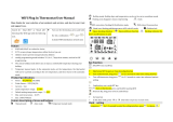
5. KEYPAD LOCK (in any operation state).
If the keys and are pressed
simultaneously for 3" (first the key and
then the ), the screen will show the
message and the keypad is locked.
Which ever key is pressed after this will
show the same message on the screen.
All other function are executed normally.
To unlock the keypad follow the same
procedure and the screen will show the
message .
6. SETTING THE TIME AND DATE (the
thermostat is in the OFF state).
To enter time and date adjustment mode
press the key for 3" as mentioned in
paragraph 1. The backlight will be activated
and the lower section of the screen will flash
the message (Set Time). After that
press briefly the key and the hours
indicators will start to blink. Use the keys
or to set the correct time.
Pressing the key will cause the
minutes indicators to blink and with the keys
or change to the correct value.
Pressing again the key you can adjust
consecutively the year, month and date.
You can see that the day names are
changed automatically depending on the
year, month and date. In normal operation
the clock has leap year and daylight
savings time correction.
7. SETTING THE DAILY PROGRAM.
(the thermostat is in the OFF state).
If immediately after entering the MENU
parameters press the key then the
blinking message (Day) will be shown
on the bottom of the screen and the word
DAY on the top right. By pressing the
key the message (Program 1) is
shown in place of the message.
In the center of the screen and if
programming is done for the first time you
can see the message . By pressing the
key the hours indicators blink and you
can alter the setting by using the
keys or . By pressing the key
you can alter the minutes and the required
temperature. With the key you can
return to the initial position with the
blinking . With consecutive presses of
the key you can select the remaining
programs of the 24 hour cycle (10 in total)
and can set the required time periods and
temperatures as described above. Please
note that for every program define only the
start time since the end time is the start time
of the next program. For example, if you
desire a temperature of 23.0º C from 14:00
to18:00 in program 1 set the start time
14:00 at 23.0º C and the start time of the
second program 18:00 with the desired
temperature. The 24 hour time base starts
at 00:00 and ends at 23:59'.
The start time of the next program must also
be bigger than the start time of the previous.
If no more changes are required and when
the program indicator is blinking (e.g. )
you can press the key to store all the
changes and the screen will show the
message . The programs that have not
been adjusted are not taken into account.
8. ADJUSTING SETTINGS FOR THE
WEEKLY PROGRAM. (the thermostat is in
the OFF state).
If immediately after entering the ΜΕΝU
press the key for 2 times the
message (7days) will be shown on the
bottom of the screen and the word WEEK
on the top right. On the top left of the screen
there is the message ΜΟ (Monday) that
shows the day that corresponds to the
programming that follows. By pressing
again the key the screen shows a
blinking that determines the first
program of Monday of the weekly program.
The remaining procedure is as described in
paragraph 7 (setting the daily program).
Finishing the programming of the first day if
you press the key while the program
number is blinking (e.g. ) will show the
blinking message . With the key
you can select the day for which you want to
alter the program as described above. If no
other changes are required then press the
key to save the setting to memory. The
screen will show the message . It is
stressed that at least one program must be
adjusted for every day else the factory
default temperature of 6.0 ºC will be used
MENU
ENTER
ESC
ESC
MENU
ENTER
MENU
ENTER
MENU
ENTER
MENU
ENTER
ESC
ESC
MENU
ENTER
Page 7 from 13
940851000_09_001
for all the 24 hour base.
9. SELECTING THE UPPER AND LOWER
L I M I T S O F T H E M A N U A L
TEMPERATURE ADJUSTMENT (the
thermostat is in the OFF state).
After entering the and by MENU
consecutive presses of the key the
message (High Temperature Limit)
will be shown on the bottom of the screen
as well as the initial value 30.0 ºC. By
pressing the key you can change this
temperature between the lower limit
and the value of 30.0 ºC. By pressing the
key and then immediately the key
the lower section of the screen shows the
message (Low Temperature Limit) as
well as the initial temperature of 6.0 ºC. With
the key you can adjust the value
between 6.0 ºC and the value of the upper
limit. The two limits define a temperature
area that can be used by the user to enter
the desired temperature. The selection of
the limits influences the manual adjustment
of the temperature and is independent from
the operating mode of the unit (manual,
daily weekly) and does not have any
influence on the programs for daily or
weekly operation.
10.OTHER MENU SETTINGS (the
thermostat is in the OFF state).
All the menu settings that follow can be
changed by using the same method as
described in the previous chapters. After
entering the use the key to ΜΕΝU
select the required setting. The messages
are shown in the bottom section of the
screen like this:
A. (Mode) OPERATION MODE.
One of three operation modes can be
selected:
(User) Manual mode (the symbol
ΜΑΝ. is shown on the top right of the
screen).
(Day) daily operation (the symbol
DAY is shown on the top right of the screen.
(7 Days) weekly program (the symbol
WΕΕK is shown on the top right of the
screen).
The factory default is .
Β. (Unit) TEMPERATURE UNIT.
The option are: or (Degree
Celsius ή Degree Fahrenheit) and regard
the display of the temperature in ºC or ºF.
Depending on the selection, the symbol ºC
or ºF are shown on the center right of the
screen.
C . ( B a c k L i g h t ) S C R E E N
ILLUMINATION.
With this setting you can turn off the screen
illumination in order to conserve battery
energy. If (ΟΝ) is selected then the
screen illumination will be activated every
time a key is pressed. If is selected
then the screen illumination will be
deactivated
The factory default is .
D. (LED) BURNER OUTPUT
INDICATOR.
This setting can deactivate the burner
output indicator in order to conserve battery
energy.. If (ON) is selected then when
the burner output is active the indicator will
briefly blink every second so the user has a
knowledge of the state of the thermostat
from a distance.. If (OFF) is selected
then the indicator is deactivated.
Ε. (Time Out) TEMPORARY TIME
FOR MANUAL OPERATION.
With this setting you can determine the time
period for which the manual temperature
adjustment is valid. When the thermostat is
running a daily or weekly program and you
press the keys or , either you
change the temperature through the
application, then the thermostat enters
briefly the manual mode for a time period
that is determined by the setting . The
value of this setting can be from 3 to 10
hours after which normal program
execution is continued. The factory default
is 3 hours.
F. (Differential) DIFFERENTIAL
SETTING.
This setting determines the temperature
win d o w be t w een a c t i vation and
deactivation of the burner output. For
example, if the room temperature is set to
23.0 °C then with a differential of 0.5 °C the
output to the burner will be deactivated at
23.0 °C and will be reactivated at 22.5 °C.
MENU
ENTER
ESC
MENU
ENTER
Page 8 from 13
940851000_09_001
The differential value can be set between
0.2 °C and 4.0 °C.
The factory default value is 0.2 °C.
G. (Heat/Cold). HEATING MODE.
The device can control only heating
units (e.g. diesel burners).
H. (Time) HOUR METER.
In this screen position you can see the total
operation hours of the burner. This value
can not be altered by the keypad but can be
reset if the battery is removed. The
maximum value is 9.999 hours.
I. (Factory settings) SELECTING
THE FACTORY DEFAULT SETTINGS.
If for any reason there is the need to restore
the thermostat to its factory default settings
then this setting will restore then if you
select and press the key .This
does not affect the time and date settings.
The factory default setting is .
11. CHANGING THE BATTERY
When the screen shows the symbol
the unit warns the user that the batteries
have limited energy and that they must be
replaced in the next 3 weeks. To replace the
batteries simple remove the cover (Fig. 2)
to expose the battery compartment.
Remove the batteries and within 30
seconds reinsert new ones in order to avoid
a reset of the device. Should this happen it
will require to adjust the time and date
again. All other setting remain unaffected.
Avoid replacing the batteries with the
backlight activated, this will immediately
reset the device and the hour meter. Take
care of the battery orientation and insert the
new batteries according to the graphic
representation etched on the plastic base.
The reverse installation will not harm the
device but it will not permit it to operate.
The battery life time has been design to be
approximately one year. Factors that
influence the battery life are prolong use of
the keyboard with the backlight active,
increased temperature and humidity as well
as battery quality.
12. ANTI-ICE PROTECTION
If the room temperature in which the
thermostat is installed falls below C, the
unit activates the burner output irrelevant of
the ON or OFF state of the thermostat to
prevent ice build up. The burner output is
active for as long as the temperature is
below C.
13. CLEANING THE THERMOSTAT
To clean the device use a damp cloth to
remove any dust or stains from the covers.
Do not use any liquid or dissolvers that will
damage the plastic covers.
14. SCREEN MESSAGES
Following you can see a complete list of
screen messages that can be seen by
consecutively pressing the key:
= =Time and date setting.Set Time
= = Daily program selection. Day
= = Weekly program selection. Week
= = Operation mode selection. Mode
= = Temperature unit. Unit
= = Screen illumination.Backlight
= = Burner output indication LED. LED
= = Manual temperature Time out
time.
= = Upper limit High Temperature Limit
for manual temperature adjustment.
= = Lower limit Low Temperature Limit
for manual temperature adjustment.
= = Active boiler timeBoiler Time
= = Differential for burner Differential
relay.
= = Absence program.Absent
= = Night program.Night
= = Heat operation mode. Heat
= RF = Wirelless connection setting
= = Factory default settings. Factory
MISCELLANEOUS INDICATIONS
= = keyboard lock.Lock
= = unlock keyboard. Unlock
= = Save settings to memory. Save
= = Manual program User
= = Celsius Degree Celsius
temperature unit.
= = Fahrenheit Degree Fahrenheit
temperature unit.
= = Program number Program 1 to 10
from 1 to 10.
MENU
ENTER
Page 9 from 13
940851000_09_001
FACTORY DEFAULT VALUES
The following values are the factory default
setting of the thermostat:
Thermostat state = Inactive (OFF)
Daily and weekly programs = Not set
Selected temperature value = 23.0°C
Normal or Night program = Normal
Temperature unit = Degrees Celsius
Screen backlight = Active (On)
Burner activation indicator = Active (On)
Presence/ Absence program = Presence
Manual selection time = 3 hours
Upper manual temperature limit = 30.0°C
Lower manual temperature limit = 6.0°C
Boiler operation time = 00 minutes (BS-
851/T)
Boiler state = Inactive (BS-851/T)
Operation mode = Manual (User)
Differential = 0.2° C
Absence temperature = 16.0° C
Night program temperature = 18.0° C
Heating function= Heating
Keypad state = Unlocked
DAILY PROGRAMMING EXAMPLE
Lets assume that you want to program the
following temperatures and hours
(programs): From 07.00 to 08.30 at 22,5°C.
From 8.30 to 12.00 at 21,5°C. From 12.00
to 17.30 at 18.5°C. From 17.30 to 23.00 at
22.5°C and from 23.00 to 07.00 at 19,8°C.
Note that the end hour of each program is
the start hour of the next program and
always the start hour of a program is at least
1 minute greater than the end hour of the
previous program. It is essential to select at
least 1 program per day otherwise the
thermostat will operate with the factory
defined temperature of 6°C. Also note that
the first program is considered the program
with the start hour nearest to the hour 00.00
(e.g. 07.00).
1. Turn OFF the thermostat by pressing the
corresponding key.
2. Press continuously the key for 3
seconds The screen back light is activated .
and the screen shows . Now you are in
programming mode of the thermostat
parameters.
3. Press the key 9 times and the screen
shows with the (Mode) blinking.
4. Press the key and the starts to
blink. With the keys and select
the operation mode (Day - daily
program).
5. Press the key to return to the
previous screen with the blinking.
6. Press the key 8 times and the screen
shows with the blinking. Now you
are in the daily programming sub menu that
has a 10 program capability.
7. Press the key and the screen
shows with the blinking, this shows
that you are in program 1 of the daily
program (the indication indicates that
the current program in empty).
8. Press the key and the hours digit
starts to blink. With the keys and
select 07.
9. Press the key and the minutes digit
starts to blink. With the keys and
select 00.
10. With the next press of the key
the screen shows the temperature blinking
and by using the and keys you
select 22,5°C. This concludes the
programming of the first program.
11. Press the key and the screen
shows the symbol blinking.
12. Press the key and the symbol
will blink. This shows that you are in the
second program.
13. Follow the step 8, 9 and 10 and set the
time to 8.30 (which is the end time of the first
program) and the temperature to 21,5°C.
14. Following the steps 8, 9, 10 and 11 to
adjust the remaining programs with the
values 12.00/18,5°C, 17.30/22,5°C and
23.00/ 19.8°C. If by mistake you add a new
program (ex. Ρ6), this program can’t be
canceled but can be defined as a new
program with a start time of 23.01 and the
same temperature as Ρ5.
15. Completing the daily program you can
store the programmed values to the devices
memory by pressing 2 times the
key while the indication is blinking.
The screen will show for awhile and
then normal operation will continue. By
activating the device with the key the
daily program will start to take affect. In
order for the program to execute correctly
make sure you have programmed the
MENU
ENTER
MENU
ENTER
ESC
DAY
MENU
ENTER
MENU
ENTER
ESC
ESC
Page 10 from 13
940851000_09_001
device clock with the correct time.
WEEKLY PROGRAMING EXAMPLE.
The weekly program in general is based on
the daily programming which is repeated for
every day of the week independently. For
the days of the week that have not been
programmed, the values of the last
programmed day are valid. For example, if
you program only the days Monday to
Wednesday, then the programming for
Wednesday will be used for the days
Thursday to Sunday. If you program only
the days Monday, Wednesday and
Thursday then for Tuesday’s program the
program from Monday will be used and for
the days Friday, Saturday and Sunday the
program from Thursday will be used.
1. Follow the steps 1, 2, 3, and 4 of the daily
programming. Select in the (Mode)
section the setting and press the
key .
2. Press 7 times the key and the
screen shows with the indication
blinking. The symbol ΜΟ (Monday) means
that you are ready to program the Monday
program and the symbol WEEK that you
are in weekly programming mode.
3. Press the key and the screen shows
. From now the procedure follows the
steps 8-14 of the daily programming and
you can set the required temperatures on
the required time.
4. Completing the programming of the
Monday program press the key and
the screen shows with the
indication blinking. By pressing the
key, the day indicator changes to TU
(Τuesday) you can repeat the steps for
programming a new program for Tuesday.
The same can be done for the rest of the
days of the week.
5. The completion of the weekly
programming can be done by pressing the
key when the indicator is
blinking. The screen will show the
message briefly and the settings will
be stored in to the devices memory.
6. Activate the device using the key.
The weekly program will start to execute as
defined. In order for the program to execute
correctly make sure you have programmed
the device clock with the correct time.
WIRELESS CONNECTION SETTING
After installing the peripheral received (BS-
851/R), press the programming key (Figure
1) until the indicator POWER/STATUS (LD1)
starts to blink in a rapid manner. This shows
that the unit is in programming mode. After
activating the thermostat by removing the
battery separation tape, go to the selection
(the thermostat in the OFF state,
prolonged press of the MENU/ENTER key
and then 22 consecutive presses of the key
lead us to the screen ). The
number of dashes verifies the correct
connection between the two devices and
also shows the strength of the signal. The
thermostat must be placed in such a
position that will allow good signal strength
which means that at least 2 dashes must be
shown. If less that 2 dashes are shown the
communication between the two devices is
not good and can lead to communication
errors and bad operation.
To completion of the wireless installation
procedure is done by pressing the key
on the thermostat and by a prolonged press
of the programming key on the peripheral
until the POWER/STATUS(LD1) indicator
stops to blink and remains ON.
MOUNTING
Select mounting areas away from heating
elements, door and window openings and
fireplaces and in general, away for all heat
sources and away from drafts. Mount the
thermostat at a height of about 1.5 meters
and on an interior wall (The external wall
have a lower temperature than the internal
wall and can affect the device).
ESC
MENU
ENTER
ESC
ESC
ESC
Page 11 from 13
940851000_09_001
Dimensions in mm
Dimensions in mm
Mounting hole spacings
COMMUNICATION ERROR
Errors can occur if for any reason the
communication between the two devices is
disrupted. The screen of the thermostat will
show the message (Communication
Error), the backlight of the screen will blink.
The interruption of the mains voltage
causes the interruption of communication
between the two devices. When the voltage
is restored, the peripheral device-receiver
activates the outputs according to the state
before the interruption, until the
communication is automatically restored
with the thermostat (maximum delay of 6
minutes), so the outputs will change
according to the new commands that will be
given.
Mounting hole spacings
81,3
27,3
121,5
105
105
19
19
80mm
120mm
120mm
34mm
Wi
Page 12 from 13
940851000_09_001
Installation procedure
Fig. 1 Fig. 2 Fig. 3
To install the devices BS-850/T or BS-851/T, insert a flat blade screwdriver in the slot as shown
in (Fig. 1). Press and lift the front cover.
Remove the retaining screws and remove the plastic cover that contains the keys (Fig. 2).
Use the supplied mount accessories to mount the unit according to the diagram of page 11.
Install the base, align it using the built in vial and tighten the screw to secure it.
Reinstall the plastic containing the keypad with care and fasten the screws with a maximum
torque of 0,5 Nm.
To activate the device, remove the battery separation tape (Fig. 3).
Install the front cover with slight pressure and the device is ready to operate.
Fig. 4
To install the BS-851/R, remove the front cover with a screwdriver
(Fig. 4). Mark and drill the mounting holes according to the
schematic in page 11. Mount the device using the supplied
mounting accessories (Holes A and B) as shown in Fig.5. Do the
electrical connections according to (Fig.5). Connect the phase to
the L terminal and the neutral to the N terminal, this is used to
power the device. The phase cable for the outputs is to the
common of the relay contacts. In every activation, the contacts will
provide the phase to the burner. Avoid installing the phase
internally (from the L terminal to the relay common terminals)
because it might cause interferences. The outputs are not fuse
protected so any short circuit will destroy them and the device.
N
L
230V~
Boiler Indicator (BS-851)
LD5
LD4
Boiler
(BS-851/R)
Burner
Fig. 5
Burner Indicator
A
B
WPS Button
Manual Button
Power/Status
Indicator
Programming button BT1
Page 13 from 13
940851000_09_001
Olympia Electronics guarantees the quality, condition and operation of the goods. The
period of warranty is specified in the official catalogue of Olympia Electronics and also
in the technical leaflet, which accompanies each product. This warranty ceases to
exist if the buyer does not follow the technical instructions included in official
documents given by Olympia Electronics or if the buyer modifies the goods provided
or has any repairs or re-setting done by a third party, unless Olympia Electronics has
fully agreed to them in writing. Products that have been damaged can be returned to
the premises of our company for repair or replacement, as long as the warranty period
is valid. Olympia Electronics reserves the right to repair or to replace the returned
goods and to or not charge the buyer depending on the reason of defection. Olympia
Electronics reserves the right to charge or not the buyer the transportation cost.
HEAD OFFICE
72nd km. O.N.R. Thessaloniki-Katerini
P.C. 60300 P.O. Box 06 Εginio Pierias Greece
www.olympia-electronics.gr
TECHNICAL CHARACTERISTICS
POWERED BY
2 Alkaline ΑΑ
BS-850/T - BS-851/T BS-850/R - BS-851/R
MODEL
220 - 240V AC / 50-60Hz
OPERATION TEMPERATURE RANGE
RELATIVE HUMIDITY
EXTERNAL DIMENSIONS
TYPICAL WEIGHT
GUARANTEE
MEASURING RANGE
OPEN RELAY CONTACT
DEGREES OF COVER PROTECTION
PRODUCED IN ACCORDANCE WITH
2x5Α - 250V AC1
o
0.0 to 99.9 C
EN 61000-6-1, EN 61000-6-3, EN 60730-1, EN 60730-2-9
o
5 to 35 C
10 - 90% RH
2 years
121.5 x 27.3 x 81.3 mm
IP20
175 gr. (with batteries) 200 gr.
o
-10 to 50 C
10 - 95% RH
120 x 34 x 80 mm
-
CONSUMPTION
1.9VA
WARRANTY
WARRANTY
-
COMMUNICATION FREQUENCY
869,75MHz
TEMPERATURE SELECTION RANGE
o
6.0 to 30.0 C
-
-
  • Page 1 1
  • Page 2 2
  • Page 3 3
  • Page 4 4
  • Page 5 5
  • Page 6 6
  • Page 7 7
  • Page 8 8
  • Page 9 9
  • Page 10 10
  • Page 11 11
  • Page 12 12
  • Page 13 13

olympia electronics BS-850/T User manual

Category
Thermostats
Type
User manual
This manual is also suitable for

Ask a question and I''ll find the answer in the document

Finding information in a document is now easier with AI