1
IMPORTANT:
IMPORTANT:
Go to www.extron.com for the complete
user guide, installation instructions, and
specifications before connecting the
product to the power source.
Quantum Ultra
®
Videowall Processor • Setup Guide
The Extron Quantum Ultra 610 and 305 and Quantum Ultra Connect 128 and 84 Videowall Processors are modular 4K video
processors that support ultra-high resolutions up to 2560x1600 and 4096x2160 (4K) on inputs and outputs. All models provide
customizable output resolutions, input and output image rotation, and mullion compensation for compatibility with most display
technologies. USB, RS-232, and Ethernet interfaces also provide direct connections for control systems.
The Quantum Ultra 610 is a 6U, 10-slot card frame, while the Quantum Ultra 305 is a 3U frame with 5 card slots. These
models support multiple videowalls with mixed resolutions and screen orientations. They also support edge blend compensation,
window border styles, and a variety of source types including picture, RSS, Text, Clock, and VNC. The optional IN SMD 100 input
card decodes and displays multiple simultaneous MPEG2, Motion JPEG, and H.264 video streams at up to 60 frames per second.
Each input card contains four HDMI or two LAN connectors. The output cards contain either four HDMI or four DTP connectors.
Both chassis support any combination of input and output cards. Additional inputs and outputs can be added to a system with
use of one or more additional chassis.
The Quantum Ultra Connect 128 and 84 have xed congurations. The Quantum Ultra Connect 84 has two HDMI input cards
and one HDMI output card, while the Quantum Ultra Connect 128 has three HDMI input cards and two HDMI output cards.
This card conguration is xed and cannot be modied by the user.
Control methods for all models include Extron Videowall Conguration Software (VCS), which can be downloaded from the
Extron website and provides a means of conguring videowall displays and saving window presets. Control is also available via
Simple Instruction Set™ (SIS) commands and by using the Express Mobile Software (EMS) for Quantum Ultra on an iOS, Android,
or Microsoft tablet device.
Rear Panel Features and Connections
Quantum Ultra Rear Panel
NOTE: Figure 1 shows the rear panel of a Quantum Ultra 610. The Quantum Ultra 305, Connect 84, and Connect 128 have
the same rear panels except that they are 3U high, have fewer card slots, and have no redundant power connector.
A
A
A
QUANTUM ULTRA 610
Tx Rx G
CONFIG
RS-232
AB
SLOT 9SLOT 10
DISCONNECT POWER
CORD BEFORE
SERVICING
100-240V ~ 5.0A MAX 50-60 Hz100-240V ~ 5.0A MAX 50-60 Hz
POWER LAN
SYSTEM REMOTE
OUTPUTS
SLOT 8
QUANTUM OUT4HDMI
OUTPUTS
SLOT 7
QUANTUM OUT4HDMI
OUTPUTS
SLOT 6
QUANTUM OUT4HDMI
INPUTS
SLOT 5
INPUTS
SLOT 4
INPUTS
SLOT 3
INPUTS
SLOT 2
INPUTS
SLOT 1
QUANTUM IN4HDMI
QUANTUM IN4HDMI
QUANTUM IN4HDMI
QUANTUM IN4HDMI
1234
1234
1234
1234
1234
1234
1234
HDBT
4A MAX
DTP POWER
12V
OUTPUTS
QUANTUM OUT4DTP
Tx Rx RxGTx
SIGLINK
OUT 4
DTP
OVER TP
Tx Rx RxGTx
SIGLINK
OUT 3
OVER TP
Tx Rx RxGTx
SIGLINK
OUT 2
OVER TP
Tx Rx RxGTx
SIGLINK
OUT 1
OVER TP
HDBT
4A MAX
DTP POWER
12V
OUTPUTS
QUANTUM OUT4DTP
Tx Rx RxGTx
SIGLINK
OUT 4
DTP
OVER TP
Tx Rx RxGTx
SIGLINK
OUT 3
OVER TP
Tx Rx RxGTx
SIGLINK
OUT 2
OVER TP
Tx Rx RxGTx
SIGLINK
OUT 1
OVER TP
B
B
B
H
H
H
G
G
GF
F
F
E
E
E
D
D
D
C
C
C
I
I
I
Quantum Ultra 610
LAN A
LAN B
INPUTS
QUANTUM IN SMD 100
1234
QUANTUM IN4HDMI
A
Primary AC power connector
B
Redundant AC power connector (Quantum Ultra 610 only)
C
Power switch
D
HDMI Out system output connector
E
USB system connectors
F
USB Config control connector
G
RS-232 control connector
H
LAN connectors A and B
I
Input and output card slots
Figure 1. Quantum Ultra 610 Rear Panel
1
Quantum Ultra • Setup Guide (Continued)
2
A
Primary AC power connector — Connect AC power to this IEC connector for the primary power supply.
B
Redundant power connector (Quantum Ultra 610 only) — (Optional) Connect a second AC power source to this IEC
connector for the secondary power supply to provide uninterrupted operation in the event of failure of the primary supply.
C
Power switch — Press the bottom of this momentary rocker switch to power the unit off and on.
z If the unit is off, pressing and releasing this switch powers it on.
z If the unit is on, pressing and holding this switch for approximately 5 seconds powers it down.
z If the unit is logged into the Quantum Ultra operating system, pressing and releasing this switch starts a safe shutdown.
D
HDMI Out system output connector — (Optional) Connect an HDMI monitor to this female HDMI connector to view
activity and interactions with the embedded operating system and the Quantum Ultra Control Panel.
E
USB system connectors — (Optional) Connect a flash drive or human interface devices (HIDs) such as a keyboard or
mouse to one or more of these three USB A connectors to enable interaction with the embedded operating system.
F
USB Config control connector — Connect a computer to this USB connector to enable control of the Quantum Ultra via
VCS and SIS commands.
G
RS-232 control connector — Connect a control system or computer to this 3-pole, 3.5 mm captive screw connector to
enable control of the Quantum via SIS commands. RS-232 protocol for this port is 9600 baud, 1 stop bit, no parity, 8 data
bits, and no ow control.
H
LAN connectors A and B — Connect one or both of these RJ-45 Ethernet connectors to a network to access:
z A computer with VCS and, optionally, EMS installed, to set up the videowall (see Configuring the Videowall on
page3).
z A control device such as an Extron IP Link Pro or IPCP for AV control of the Quantum Ultra.
z A network with Virtual Network Computing (VNC) servers to stream desktops to the Quantum Ultra.
I
Input and output card slots — Each of these slots supports either an input or an output card. At least one input and one
output card must be installed.
The Quantum Ultra Connect 84 has two input cards and one output card, while the Quantum Ultra Connect 128 has three
input and two output cards. These card congurations are xed and cannot be modied by the user.
z Each HDMI input card has four female HDMI connectors, to which you can connect up to four HDMI sources. For the
Quantum Ultra 610 and 305, each IN SMD 100 input card has two LAN connectors, each of which can be connected to a
network to enable decoding and displaying of multiple streams.
z Each output card has either four HDMI connectors or, for Quantum Ultra 610 and 305, four DTP connectors. You can
connect up to four HDMI displays or DTP receivers to these output cards.
Installation Steps
WARNING: To avoid electric shock or product damage due to condensation, always let the Quantum Ultra become
acclimated to ambient temperature and humidity for at least 30 minutes before switching it on. This is very important
when you are moving the unit from a cold to a warm location.
AVERTISSEMENT : Afin d’éviter un risque éventuel de choc électrique ou d’endommagement du produit dû à la
condensation, laisser toujours le temps à la source d’alimentation de le Quantum Ultra à la température et à l’humidité
ambiantes, pendant au moins 30minutes, avant de les brancher. Ceci est particulièrement important lorsque vous
déplacer l’unité depuis un lieu frais vers un lieu chaud.
ATTENTION:
All structural steps and electrical installation must be performed by
qualified personnel in accordance with local and national building
codes and electrical codes.
Toute étape structurelle et installation électrique, doit être effectuée
par un personnel qualifié, conformément aux codes du bâtiment,
aux codes incendie et sécurité, et aux codes électriques, locaux et
nationaux.
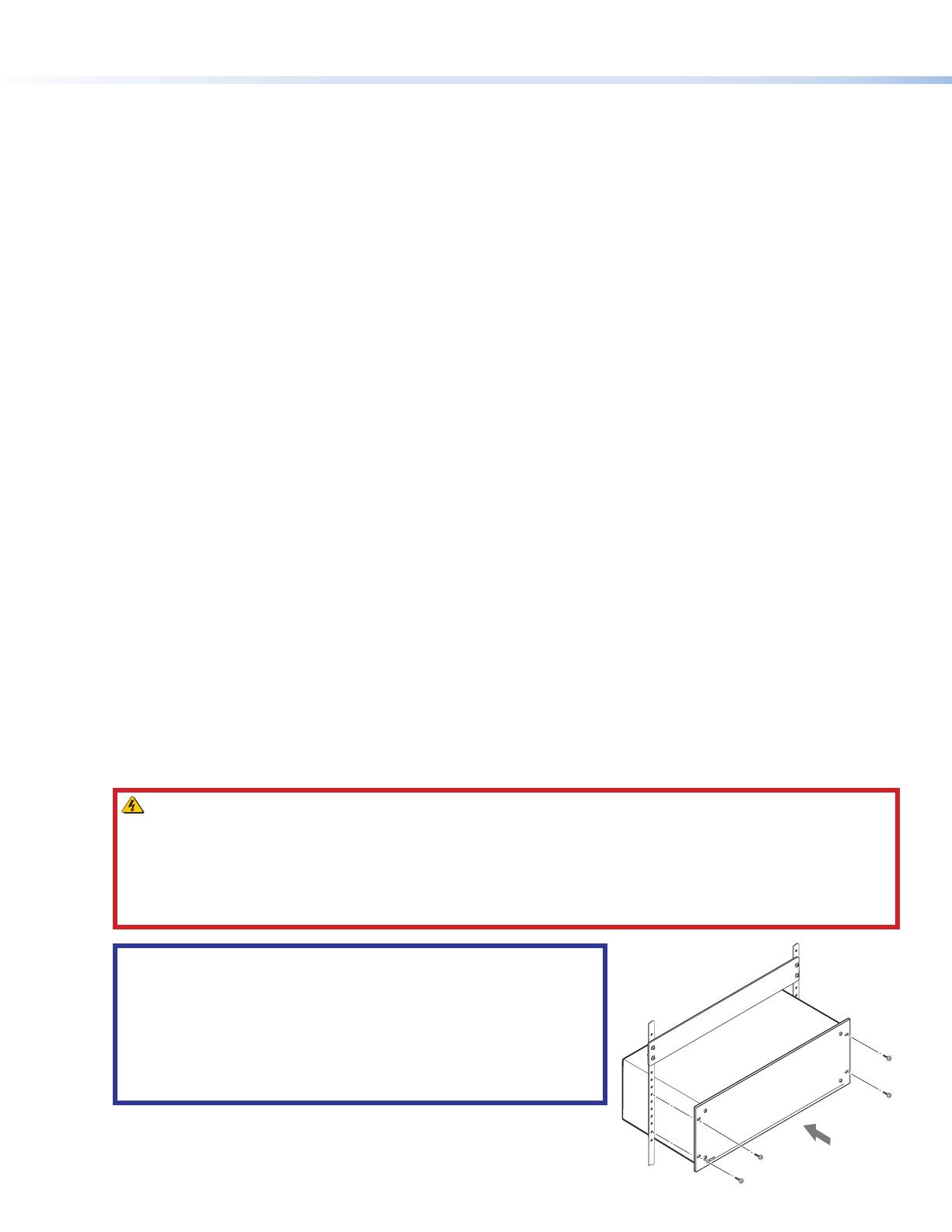
1. Disconnect power from all equipment.
2. (Optional) Mount the unit to a rack using the supplied screws (see the
image at right).
Product Category
3
3. Connect the video inputs and outputs. Connect HDMI sources to connectors on the installed HDMI input cards. If
IN SMD 100 input cards are installed (Quantum Ultra 610 and 305 only), connect the LAN connectors on the cards to a
network for streaming sources. Connect DTP receivers (Quantum Ultra 610 and 305 only) or HDMI displays to connectors on
the output cards. Secure each HDMI device cable to the connector with a provided LockIt
®
HDMI Cable Lacing Bracket.
4. Connect a control device — For remote control, connect a control device or a computer to:
z The RJ-45 LAN A to enable configuration and control of the Quantum Ultra via SIS commands, VCS, or EMS
z (Optional) The USB mini B Config connector to enable configuration and control via SIS commands or VCS
z (Optional) The 3-pole captive screw RS-232 connector to enable serial control via SIS commands
5. Connect power to the Quantum Ultra primary and redundant (optional) IEC connectors.
6. Power on the Quantum Ultra and all connected devices.
7. Download and install the Videowall Configuration Software on your computer.
8. Configure sources, displays, EDID, and presets for your videowall system using VCS (see “Configuring the Videowall”).
Configuring the Videowall
This section describes how to set up the videowall using the VCS program to congure and control the Quantum Ultra from the
computer. For detailed information, see the Videowall Configuration Software Help File, accessible from VCS.
Starting the Software
1. Download VCS from www.extron.com (see the Quantum Ultra User Guide, also available on the Extron website, for
instructions).
2. Open the software program either by double-clicking the VCS icon that is placed on your desktop during
installation (shown at right), or by clicking Start > All Programs > Extron Electronics > Videowall
Configuration Software. The Extron VCS program opens with the Start screen, Create New Project tab
(see figure2) and a list of devices supported by the current version of VCS.
Figure 2. VCS Start Screen, Create New Project Tab
3. Select the radio button for your device and click the Create button (
1
). VCS searches for Quantum Ultra Devices that are
on the network. The Connect to Device screen is displayed. In the Select Device(s) to Add: panel (see figure3,
1
, on
the next page) are displayed all detected devices of the type you selected on the Create New Project screen.
NOTE: A gateway IP address is required on the PC running VCS, in order for the Quantum Ultra to be detected. The
gateway address need not be valid or on the same subnet.
4. Locate your Quantum Ultra on the device list and click the Add to System button at the left of the device name. If a project
already exists on the selected device, a prompt opens, asking if you want to apply your new project to the device (deleting
the previous project). Click OK to continue creating the project (or Cancel to stop the procedure).
Connection information is displayed in the System Devices panel. If the computer is successfully connected to the device,
the word Connected is displayed, preceded by a green dot, in the System Devices panel (
2
).
NOTE: Multiple Quantum Ultra 610 and 305 devices can be added to a product. Only one Quantum Ultra Connect
device can be added.
2
Quantum Ultra • Setup Guide (Continued)
4
Figure 3. Connection Screen
If you do not see your device in the Select Device(s) to Add panel:
a. Click the Manually Add Device button (see figure3,
3
). The
Manually Add Device window opens (shown at right).
b. In the IP Address field, enter the address of the Quantum to be
connected and select the Pull from Hardware radio button.
c. Select the device type from the Device Type drop-down list.
Quantum Ultra devices can be selected if a Quantum Ultra 305 or
610 project was created. Quantum Ultra Connect devices can be
selected if a Quantum Ultra Connect 84 or 128 was created.
d. Click Add. The connection information for the device is displayed in the System Devices panel (
2
). A unit added by this
method is not displayed in the Select Device(s) to Add panel.
5. Edit IP address settings for your device as needed.
a. In the Select Device(s) to Add panel, click the Edit button (see
1
in the image below).
b. The Communication Settings dialog box opens. In this window, you can enter a new IP address and edit other IP
settings as desired.
To enable Dynamic Host Conguration Protocol (DHCP), select the DHCP checkbox. When this box is selected, an
available IP address is assigned automatically to the Quantum when it is connected to a supporting network. (When this
box is selected, all other IP settings elds become read-only.)
If you added this device manually, click the Device Settings button (shown at right) on the taskbar.
On the Device Details screen, click the Communication Settings button to display the
Communication Settings window. If the device cannot be detected or manually added, connect to
the Quantum Ultra using USB or RS-232 and congure the IP address using SIS commands.
Setting Up the Videowall Using VCS
To use the VCS program to congure the videowall, start by setting up a project. In the project, you can dene the Quantum Ultra
processors, create one or more videowalls, set up video sources and outputs, and create presets. At the top of the Quantum Ultra
screen is a row of task buttons. After connecting to the desired Quantum Ultra device (processor or chassis) or devices, click the
task buttons to access screens for the setup tasks. For best results, perform the following setup procedures in the order shown.
Wall Configuration
Click the Wall Conguration button (shown at right) to congure the outputs and to select the output
channels on the Quantum Ultra device or processors for the videowall. The Wall Conguration window
opens, providing a Canvas to set up the wall (see figure4 on page5).
3
Product Category
5
1. Name the Canvas. By default, the first videowall configuration (Canvas) you define is named Canvas 1 (see figure4,
1
).
In the Canvas Name field, you can customize the name if desired (
2
). Each Canvas that is created (a maximum of 10) is
assigned an incremented number that appears in the Canvas ID field and is used in SIS commands.
NOTE: The Quantum Ultra Connect models support only one canvas.
2. Select the number of displays. In the incremental spin boxes labeled Number of Displays (
3
) select or enter the
number of displays that will be in the columns and the rows of the videowall. In the example, the wall has five columns by
three rows (
4
).
Figure 4. Wall Configuration Window
3. Configure the outputs. The settings on the menus in the output configuration panel apply to all displays in the Canvas:
z Resolution (
5
) — From this drop-down list, select the output resolution for the displays.
z Master Refresh Rate (
6
) — From this drop-down list, select the refresh rate for the displays.
NOTE: Quantum Ultra 610 and 305 only: This rate not only applies to all the displays on the first Canvas, but limits
selectable refresh rates on all other Canvases that are added (see the VCS help file to use multiple Canvases).
z Output format (
7
) — From this drop-down list, select the output format (AUTO, DVI RGB 444 or
HDMI RGB 444). The default is Auto.
z HDCP Mode (
8
) — From this drop-down list, select how to manage HDCP encryption on the
outputs. You can select to always encrypt the output (default), to never encrypt the output, or to
attempt to encrypt the output for 1 minute, then revert to an unencrypted state (not allowing display
of HDCP encrypted sources if authentication with the sink device fails).
z HDCP Notification (
9
) — From this drop-down list, select to enable or disable a green screen
notification when the input signal contains HDCP-protected content and the outputs cannot be
encrypted.
z Display Rotation (
¢
) — In this panel, select the radio button for the angle at which the displays
physically rotate: +90° (90 degrees clockwise), -90° (90 degrees counterclockwise) or (no
rotation). The example at right shows a videowall that has four rotated displays.
NOTE: Output rotation is available only on the even numbered channels and disables the odd numbered channels.
4. Define the Quantum device and output in the output assignment panel (
£
) for each display on the videowall by either of
the following methods:
z Automatic method — (Recommended) Click the Auto Assign Outputs button (
¤
) to automatically assign a device
and an output channel to each display in the videowall. Output card slot and connector numbers are assigned to the
displays in numerical order. The displays are shown on the Canvas numbered from left to right, starting in the upper-left
corner with Display 1.
4
Quantum Ultra • Setup Guide (Continued)
6
z Manual method
a. Select a Quantum device for a display on the videowall. Click <Undefined> beside the
number of the display to be assigned, and select a device from the drop-down menu.
b. Select an output card and slot number for the display. Click <Undefined> in the Output
Assignment column, in the row of the display to be assigned. On the output drop-down list, all
output connectors are listed in order by card slot number and connector number. In the
example at right, 5.1 signifies connector 1 on the output card in slot 5 on the device.
Repeat these steps for each display on the videowall to which you want to assign a Quantum
device and output connector. (This guide assumes you are conguring a videowall with one device.
For information on conguring a videowall with multiple processors, see the VCS Help File).
5. In the Mullion/Edge Blending Compensation panel (see figure4,
¥
, on the previous page) select
either of the following radio buttons (for more detailed information, see the VCS Help File):
z Mullion Compensation — Displays controls that let you specify the mullion space around the displays in pixels, inches,
centimeters, or millimeters. If not using pixel values, you must also enter the diagonal size of the screen.
z Edge Blending (Quantum Ultra 610 and 305 only) — Displays controls that let you specify the amount in pixels of
horizontal and vertical overlap of the videowall outputs.
6. If desired, select a test pattern from the menu in the Test Pattern panel (
¦
) to aid in optimizing the wall configuration.
Source Configuration
Each source used in a project must have a corresponding source denition in VCS. To congure the sources:
1. On the taskbar, click the Source Configuration button (see figure5,
1
) to display the Source Configuration screen.
2. Select a source type. In the Source Configuration Tree (left panel), click a source type to add (
2
). Depending on the
cards installed in your unit, HDMI, IP Source, or both may be listed. Picture, Clock, VNC, Text, and Really Simple Syndication
(RSS) source types are always available for configuration.
NOTE: Source type selection is available only on Quantum Ultra 610 and 305. The Quantum Ultra Connect models
support only HDMI sources.
Figure 5. Source Configuration Window (IP Source Example)
5
Product Category
7
3. Add a source. Click Add (see figure5,
3
, on the previous page) to add a source of the selected type, or right-click
the source type to add and select Add from the pop-up menu. One or more source names are added in the Source
Configuration Tree below the source type (
4
).
NOTE: The number of sources added depends on the cards installed in your unit. For example, if one HDMI input card is
installed, selecting HDMI displays four source names, as shown in figure5).
4. Configure the selected source. In the Source Configuration Tree, click the source name to be configured. (It may
be necessary to click the + sign to the left of the source type to expand the source list before selecting a source). A
configuration window for the selected source opens in the center panel of the screen, with the default name of the source
entered in the Input Name field (
5
). Fill in the information in the source configuration window to set up the source.
NOTE: Quantum Ultra 610 and 305 only: If adding a picture or an IP source, click the Detect button
(
6
) above the Source Configuration Tree to:
Open a window listing the URLs of available streams (IP Source), detected using Session Announcement Protocol
(SAP) and Open Network Video Interface Forum (ONVIF) protocols. By default, the IP addresses on the IN SMD 100
cards are set to DHCP On.
List the image les available on your Quantum Ultra chassis (Picture).
5. Add more sources as desired. Repeat steps 2 through 4 to add and configure additional sources (see the Quantum Ultra
Help File for details on configuring the different sources.
Window Preset Configuration
A window preset, or scene, is a set of one or more windows in which video sources are displayed on a
videowall. Window layout parameters, including size, position, and content, are stored in the presets.
Presets can be recalled and displayed using VCS or SIS commands (see the Recall window preset
command on the next page).
1. On the taskbar, click the Preset Configuration task button to display the preset configuration workspace (see figure6,
1
).
The Canvas in this workspace is a virtual representation of the videowall you set up on the Wall Configuration screen (see
Configuring the Videowall on page3).
Figure 6. Preset Configuration Window
2. Click the Live or Preview button (
2
) to select the mode in which you want to configure the preset (see the Quantum Ultra
Help File for more information on configuration modes).
3. Specify the sources to be displayed on the videowall by adding source windows:
a. Click on a source name (HDMI, IP, Picture, Clock, VNC, Text, or RSS) in the Sources (left)
panel (
3
), and drag it to the desired location on the Canvas. A window containing the
source name appears on the Canvas. You can also drag in a Window without Source, for
which no input signal is displayed in the window on the Canvas.
6
68-2760-50
Rev. E 06 20
8
© 2017-2020 Extron Electronics — All rights reserved. All trademarks mentioned are the property of their respective owners. www.extron.com
b. Configure the source window by doing the following as needed:
z Resize it by clicking on it and dragging the resizing handles at the sides and corners.
z Reposition it by dragging and dropping it at the desired location on the Canvas.
z Double-click on it to fill the display or displays on which it was placed.
z Change the source in the window by right-clicking and dragging a different source onto the source
window. Drop the new source when the target window turns red (shown at right).
z Right-click on it and select Window Configuration from the menu. In the Window Configuration dialog box,
specify parameters for the window border, text on the border, and overlay text (Quantum Ultra 610 and 305 only).
4. If a window completely or partially covers another window, set the priority for each window by
selecting the window, then clicking a priority icon on the toolbar above the Canvas (see figure6,
4
, on the previous page). The priority number of the window (P1, P2, and so on) is displayed in the
lower-left corner of the window on the Canvas (see the image in step 3a on the previous page). You can also use this toolbar
to align multiple windows with each other and to set the size of multiple windows on the Canvas.
5. When finished, save the window layout as a preset as follows:
a. In the Presets list in the lower-left corner of the screen (
5
), select a slot to which the preset will be saved.
b. Click Save. The preset slot becomes a text field with the label Window Preset nnn (where
nnn is the 3-digit preset number that indicates the preset slot number).
c. Enter a name for the preset (32 characters maximum) or click outside the text field to keep
the current name.
6. If configuring in Preview mode, click the Take button (
6
) if you want to apply the preset to all displays in the system.
Basic SIS Commands
Command
ASCII Command
(Host to Scaler)
Response
(Scaler to Host)
Additional Description
Input Selection
Select input
X#
*
X%
*
X!
! Grp
X#
Win
X%
In
X!]
Select input
X!
for window
X%
on Canvas
X#
.
View current input
X#
*
X%
!
X!]
View current input
X!
in window
X%
on Canvas
X#
.
Window Presets
Recall window preset
1*
X#
*
X2%
. 1Rpr
X#
*
X2%]
Recall window preset
X2%
on Canvas
X#
.
Window Border Style (These commands apply to Quantum Ultra 610 and 305 only.)
Set window border style
E
B
X#
*
X%
*
X7%
WNDW
}
Wndw B
X#
*
X%
*
X7%]
Set the border style of window
X%
, on Canvas
X#
,
to
X7%
.
View window border style
E
B
X%
WNDW
} X7%]
View border style
X7%
for window
X%
on Canvas
X#
.
IP Configuration (These commands apply only to the LAN A port. A Commit and Reboot is required for changes to persist.)
Set DHCP on and off
E
X1)
DH
}
Idh
X1)]
Enable or disable DHCP.
View DHCP setting
E
DH
} X1)]
View DHCP setting
X1)
. Default is 0 (off).
Set IP address
E
X11$
CI
}
Ipi
X11$]
Set the IP address for the unit to
X11$
.
View IP address
E
CI
} X11$]
View IP address
X11$
.
Rebooting the System
Commit and reboot
E
1BOOT
}
Boot1
]
Commit changes and reboot Quantum Ultra.
KEY:
X!
= Input (assigned by VCS): 00019999. Response is four digits with leading zeros.
00010999 = physical video connections on all Quantum chassis in the system.
10009999 = Sources dened in the system and not connected to an input card.
X#
= Canvas: 0110. Response is two digits with a leading zero.
X%
= Window: 001999. Response is three digits with leading zeros.
X1)
= On or off: 0 = off (disabled), 1 = on (enabled).
X2%
= Window preset: 001128. Response is three digits with leading zeros.
X7%
= Window border style preset: 000127. 000 = no border. Response is three digits with leading zeros.
X11$
= IP address in the format nnn.nnn.nnn.nnn. Default is 192.168.254.254.
For information on safety guidelines, regulatory compliances, EMI/EMF compatibility, accessibility, and
related topics, see the Extron Safety and Regulatory Compliance Guide on the Extron website.
  • Page 1 1
  • Page 2 2
  • Page 3 3
  • Page 4 4
  • Page 5 5
  • Page 6 6
  • Page 7 7
  • Page 8 8

Ask a question and I''ll find the answer in the document

Finding information in a document is now easier with AI