Grandstream GWN7803 Installation guide

Type
Installation guide

Grandstream GWN7803 is an enterprise-grade managed network switch designed for small to medium businesses. It offers advanced Layer 2+ features such as VLAN segmentation, QoS prioritization, and IGMP Snooping for optimized network performance. With 24 Gigabit Ethernet ports, including PoE+ support on all ports, the GWN7803 can power IP phones, cameras, and wireless access points. It also has 4 SFP ports for fiber connectivity. Management options include a local web UI, console port, and compatibility with Grandstream's GWN Manager and GWN.Cloud platforms for centralized management.

Grandstream GWN7803 is an enterprise-grade managed network switch designed for small to medium businesses. It offers advanced Layer 2+ features such as VLAN segmentation, QoS prioritization, and IGMP Snooping for optimized network performance. With 24 Gigabit Ethernet ports, including PoE+ support on all ports, the GWN7803 can power IP phones, cameras, and wireless access points. It also has 4 SFP ports for fiber connectivity. Management options include a local web UI, console port, and compatibility with Grandstream's GWN Manager and GWN.Cloud platforms for centralized management.

Grandstream Networks, Inc.
126 Brookline Ave, 3rd Floor
Boston, MA 02215. USA
Tel : +1 (617) 566 - 9300
Fax: +1 (617) 249 - 1987
www.grandstream.com
For Certication, Warranty and RMA information, please visit
www.grandstream.com
GWN7800 Series
Entreprise Layer 2+
Managed Network Switch
Quick Installation Guide
~ 2 ~~ 1 ~
EN OVERVIEW
The GWN7800 series are Layer 2+ managed network switches that
allow small-to-medium enterprises to build scalable, secure, high per-
formance, and smart business networks that are fully manageable. It
supports advanced VLAN for exible and sophisticated trac segmenta-
tion, advanced QoS for automated detection & prioritization of latency
sensitive voice/video trac, IGMP Snooping for network performance
optimization, and comprehensive security capabilities against potential
attacks. The PoE models provide smart dynamic PoE output to power
IP phones, IP cameras, Wi-Fi access points and other PoE endpoints.
The GWN7800 series can be managed in a number of ways, including
the local network controller embedded in the GWN7800 series switch,
any GWN7000 series router with integrated local master, Grandstream’s
free on-premise network management software (GWN Manager), as well
as Grandstream’s cloud network management platform (GWN.Cloud).
The GWN7800 series are best value enterprise-grade managed network
switches for small-to-medium businesses.
PRECAUTIONS
Do not attempt to open, disassemble, or modify the device.
Do not expose this device to temperature outside range of 0 °C to 45 °C for
operation and -10 °C to 60 °C for storage.
Do not expose the GWN7800 to environments outside of the following hu-
midity range: 10-90% RH (non-condensing) for operation and 5-95% RH
(non-condensing) forstorage.
Do not power cycle your GWN7800 during system boot up or rmware up-
grade. You may corrupt rmware images and cause the unit to malfunction.
PACKAGE CONTENTS
GWN7800 Series Switch 1x 25cm Ground
Cable
1x 1.2m (10A) AC Cable
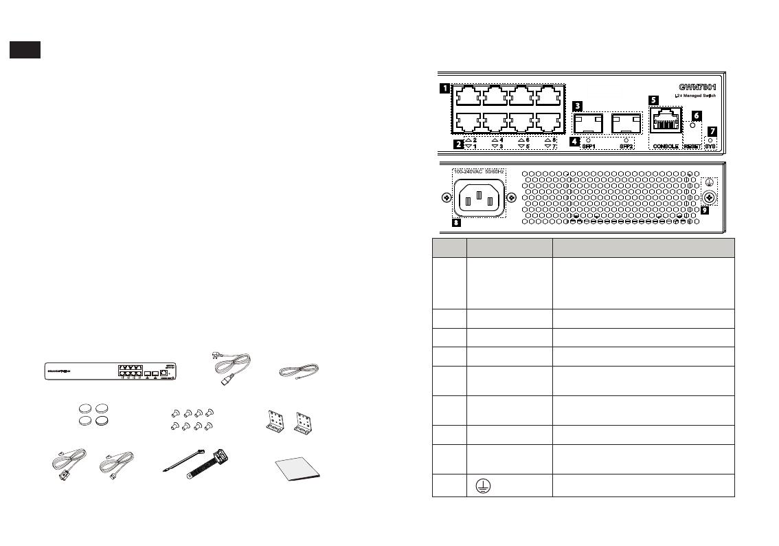
PORTS & LED Indicator
4x Rubber Footpads
8x Screws (KM 3*6) 2x Rack Mounting Kits
GWN7801/GWN7801P
9
8
No. Port & LED Description
1Port 1-8 8x Ethernet RJ45 (10/100/1000Mbps),
used for connecting terminals.
Note:
GWN7801P Ethernet ports support
PoE and PoE+.
2 1-8 Ethernet ports’ LED indicators
3Port SFP1/2 2x 1000Mbps SFP ports
4SFP 1/2 SFP ports’ LED indicators
5 Console 1x Console port, used for connecting
managing PC
6RESET Factory Reset pinhole. Press for 5
seconds to reset factory default settings
7 SYS System LED indicator
8100-240VAC
50-60Hz
Power socket
9Lighting protection grounding post
1
2
3
4
5
6
7
or
1x Quick Installation
Guide
1x Power Cord Anti-
Trip (Optional)
1x Console Cable
(Optional)
~ 4 ~~ 3 ~
GWN7802/GWN7802P
No. Port & LED Description
1Port 1-16 16x Ethernet RJ45 (10/100/1000Mbps),
used for connecting terminals.
Note:
GWN7802P Ethernet ports support PoE
and PoE+.
2 1-16 Ethernet ports’ LED indicators
3Port SFP1/2/3/4 4x 1000Mbps SFP ports
4SFP 1/2/3/4 SFP ports’ LED indicators
5 Console 1x Console port, used for connecting
managing PC
6RESET Factory Reset pinhole. Press for 5 seconds
to reset factory default settings
7 SYS System LED indicator
8100-240VAC
50-60Hz
Power socket
9
Lighting protection grounding post
10
Fan
1x Fan
2
1
3
4
567
8
9
GWN7802
GWN7802P
8
9
10
GWN7803/GWN7803P
No. Port & LED Description
1Port 1-24 24x Ethernet RJ45 (10/100/1000Mbps),
used for connecting terminals.
Note:
GWN7803P Ethernet ports support PoE
and PoE+.
2 1-24 Ethernet ports’ LED indicators
3Port SFP1/2/3/4 4x 1000Mbps SFP ports
4SFP 1/2/3/4 SFP ports’ LED indicators
5 Console 1x Console port, used for connecting
managing PC
6RESET Factory Reset pinhole. Press for 5 seconds
to reset factory default settings
7 SYS System LED indicator
8100-240VAC
50-60Hz
Power socket
9Lighting protection grounding post
10
Fan
2x Fans
1
24
3567
8
9
GWN7803
8
9
10
GWN7803P
~ 6 ~~ 5 ~
LED Indicator
LED
Indicator
Status Description
System
Indicator
O Power o
Solid green Booting
Flashing green Upgrade
Solid blue Normal use
Flashing blue Privisioning
Solid red Upgrade failed
Flashing red Factory reset
Port
Indicator
O For all ports, port o
For SFP ports, port failure
Solid green Port connected and there is no
activity
Flashing green Port connected and data is
transferring
Solid yellow Ethernet port connected and PoE
powered
Flashing yellow Ethernet port connected, data is
transferring and PoE powered
Alternately ashing
yellow and green
Ethernet port failure
Ground bar
Ground Terminal
Ground Cable
Powering on the Switch
Connect the power cable and the switch rst, then connect the power
cable to the power supply system of the equipment room.
POWERING & CONNECTING
Grounding the Switch
1. Remove the ground screw from the back of switch, and connect one
end of the ground cable to the wiring terminal of switch.
2. Put the ground screw back into the screw hole, and tighten it with a
screwdriver.
3. Connect the other end of the ground cable to other device that has
been grounded or directly to the terminal of the ground bar in the
equipment room.
Connecting Power Cord Anti-Trip(Optional)
1. Place the smooth
side of the xing strap
towards the power
outlet and insert it into
the hole on the side
of it.
In order to protect the power supply from accidental disconnection, it’s
recommended to purchase a power cord anti-trip for installation.
~ 8 ~~ 7 ~
2. After plugging the power cord into the power outlet, slide the
protector over the remaining strap until it slides over the end of the
power cord.
3. Wrap the strap of the protective cord around the power cord and lock
it tightly. Fasten the straps until the power cord is securely fastened.
RJ45 port
Crystal head
RJ45 port
2. After powered on, check the status of the port indicator. If on, it
means that the link is connected normally; if o, it means the link is
disconnected, please check the cable and the peer device whether
is enabled.
Connect to SFP Port
The installation process of the ber module is as follows:
1. Grasp the ber module from the side and insert it smoothly along
the switch SFP port slot until the module is in close contact with the
switch.
SFP port
Fiber module
PORT CONNECTING
Connect to RJ45 Port
1. Connect one end of the network cable to the switch, and the other
end to the peer device.
2. When connecting, pay attention to conrm the Rx and Tx ports of
SFP ber module. Insert one end of the ber into the Rx and Tx ports
correspondingly, and connect the other end to another device.
3. After powered on, check the status of the port indicator. If on, it
means that the link is connected normally; if o, it means the link is
disconnected, please check the cable and the peer device whether
is enabled.
Notes:
Please select the optical ber cable according to the module type.
The multi-mode module corresponds to the multi-mode optical ber,
and the single-mode module corresponds to the single-mode optical
ber.
Please select the same wavelength optical ber cable for connection.
Please select an appropriate optical module according to the
actual networking situation to meet dierent transmission distance
requirements.
The laser of the rst-class laser products is harmful to eyes. Do not
look directly at the optical ber connector.
~ 10 ~~ 9 ~
Connect to Console Port
1. Connect the RJ45 end of the console cable to the console port of
switch.
2. Connect the other end of the console cable to the DB9 male connector
or USB port to the PC.
Rubber footpads
Back of the Switch
Circular groove
Install on the Wall
1. Use the matching screws (KM 3*6) to x the two L-shaped rack-
mounting kits (rotated 90°) on both sides of switch.
2. Stick the switch port up and horizontally on the selected wall, mark
the position of the screw hole on the L-shaped rack-mounting kits with
a marker. Then, drill a hole at the marked position with an impact drill,
and drill the expansion screws(prepared by yourself) into the drilled
hole in the wall.
3. Use a screwdriver to tighten the screws(prepared by yourself) that
have passed through the L-shaped rack-mounting kits to tighten the
expansion solenoids to ensure that the switch is rmly installed on
the wall.
INSTALLATION
Install on the Desktop
1. Place the bottom of switch on a suciently large and stable table.
2. Peel o the rubber protective paper of the four footpads one by one,
and stick them in the corresponding circular grooves at the four
corners of the bottom of the case.
3. Flip the switch over and place it smoothly on the table
Install on a 19” Standard Rack
Note: GWN7802/GWN7802P/GWN7803/GWN7803P support rack
mounting.
1. Check the grounding and stability of the rack.
2. Install the two L-shaped rack-mounting in the accessories on both
sides of switch, and x them with the screws provided (KM 3*6).
~ 12 ~~ 11 ~
Method 2: Login using the Web UI
Method 3: Login Remotely using SSH/Telnet
1. Use the console cable to connect the console port of switch and the
serial port of PC.
2. Open the terminal emulation program of PC (e.g. SecureCRT),
enter the default username and password to login. (The default
administrator username is “admin” and the default random password
can be found at the sticker on the GWN7800 switch).
1. Turn on the Telnet of switch.
2. Enter “cmd” in PC/Start.
3. Enter telnet 192.168.0.254 in the cmd window.
4. Enter the default username and password to login(The default
administrator username is “admin” and the default random
password can be found at the sticker on the GWN7800 switch).
Method 4: Congure using GWN.Cloud / GWN Manager
Type https://www.gwn.cloud in the browser, and enter the account
and password to login the cloud platform. If you don’t have an account,
please register rst or ask the administrator to assign one for you.
ACCESS & CONFIGURE
Method 1: Login using Ethernet port
1. A PC uses a network cable to correctly connect any RJ45 port of
switch.
2. Set the Ethernet (or local connection) IP address of the PC to
192.168.0.x (“x” is any value between 1-253), and the subnet mask to
255.255.255.0, so that it is in the same network segment with switch
IP address.
The GNU GPL license terms are incorporated into the device rmware and an be
accessed via the Web user interface of the device at my_device_ip/gpl_license.
It can also be accessed here: https://www.grandstream.com/legal/open-source-
software To obtain a CD with GPL source code information please submit a written
request to: [email protected]
Refer to online documents and FAQ for more detailed information:
https://www.grandstream.com/our-products
3. Place the switch in a proper position in the rack and support it by the
bracket.
4. Fix the L-shaped rack-mounting to the guide grooves at both ends of
the rack with screws(prepared by yourself) to ensure that the switch
is stably and horizontally installed on the rack.
3. Type the switch’s default management IP address http://192.168.0.254
in the browser, and enter username and password to login(The default
administrator username is “admin” and the default
random password
can be found at the sticker on the GWN7800 switch)
U. S. FCC Part 15 Regulatory Information
This device complies with part 15 of the FCC Rules. Operation is subject to the following two
conditions:
(1) this device may not cause harmful interference, and
(2) this device must accept any interference received, including interference that may cause
undesired operation.
Any Changes or modifications not expressly approved by the party responsible for compliance
could void the user's authority to operate the equipment.
Note:This equipment has been tested and found to comply with the limits for a Class A digital
device, pursuant to part 15 of the FCC Rules. These limits are designed to provide reasonable
protection against harmful interference when the equipment is operated in a commercial
environment. This equipment generates, uses, and can radiate radio frequency energy and, if not
installed and used in accordance with the instruction manual, may cause harmful interference to
radio communications. Operation of this equipment in a residential area is likely to cause harmful
interference in which case the user will be required to correct the interference at his own expense.
CAN ICES-003 (A)/NMB-003(A)
If trouble is experienced with this equipment, please contact (Agent in the US):
Company Name: Grandstream Networks, Inc.
Address: 126 Brookline Ave, 3rd Floor Boston, MA 02215, USA
Tel: 1-617-5669300
Fax: 1-617-2491987
  • Page 1 1
  • Page 2 2
  • Page 3 3
  • Page 4 4
  • Page 5 5
  • Page 6 6
  • Page 7 7
  • Page 8 8

Grandstream GWN7803 Installation guide

Type
Installation guide

Grandstream GWN7803 is an enterprise-grade managed network switch designed for small to medium businesses. It offers advanced Layer 2+ features such as VLAN segmentation, QoS prioritization, and IGMP Snooping for optimized network performance. With 24 Gigabit Ethernet ports, including PoE+ support on all ports, the GWN7803 can power IP phones, cameras, and wireless access points. It also has 4 SFP ports for fiber connectivity. Management options include a local web UI, console port, and compatibility with Grandstream's GWN Manager and GWN.Cloud platforms for centralized management.

Ask a question and I''ll find the answer in the document

Finding information in a document is now easier with AI