JetStream Smart Switch
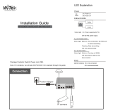
04Introduction
LED Indication
1000Mbps
On: Running at 1000 Mbps.
Off: Running at 10/100 Mbps or no device is linked to the corresponding port.
Note: For T1600G-18TS (TL-SG2216)/1700G-28TQ.
1000M
10/100/1000Mbps
Green On: Running at 1000 Mbps, but no activity.
Green Flashing: Running at 1000 Mbps and is transmitting or receiving data.
Yellow On: Running at 10/100 Mbps, but no activity.
Yellow Flashing: Running at 10/100 Mbps and is transmitting or receiving data.
Off: No device is linked to the corresponding port.
Note: 1000M for T1500-28TC. 10/100/1000Mbps for port 1–24 of T1600G-28TS and
port 1–48 of T1600G-52TS (TL-SG2452).
100Base-FX
1000Base-X
Green On: A 1000 Mbps device is connected to the corresponding port but no
activity.
Green Flashing: A 1000 Mbps device is linked to the corresponding port and data is
being transmitted or received.
Yellow On: A 10/100 Mbps device is connected to the corresponding port but no
activity.
Yellow Flashing: A 10/100 Mbps device is linked to the corresponding port and is
transmitting or receiving data.
Off: No device is linked to the corresponding port.
Note: 1000Base-X for port 25–28 of T1600G-28TS. 100Base-FX/1000Base-X for
port 49–52 of T1600G-52TS (TL-SG2452).
Port 49–52 of T1600G-52TS (TL-SG2452) doesn't support 10 Mbps devices.
25–28
Link/Act
Green On: Running at 10 Gbps, but no activity.
Green Flashing: Running at 10 Gbps and is transmitting or receiving data.
Yellow On: Running at 1000 Mbps, but no activity.
Yellow Flashing: Running at 1000 Mbps and is transmitting or receiving data.
Off: No device is linked to the corresponding port.
Note: 25–28 for T1700G-28TQ. Link/Act for port 13–16 of T1700X-16TS.
Link/Act
Green On: Running at 10 Gbps, but no activity.
Green Flashing: Running at 10 Gbps and is transmitting or receiving data.
Yellow On: Running at 100/1000 Mbps, but no activity.
Yellow Flashing: Running at 100/1000 Mbps and is transmitting or receiving data.
Off: No device is linked to the corresponding port.
Note: Only for port 1–12 of T1700X-16TS.
Master
On: The switch works as master in the stack system, or does not join any stack
system.
Off: The switch works as stack member in the stack system.
Note: Only for T1700G-28TQ.
Fan
Green: All the fans work properly.
Yellow: Not all the fans work properly.
Off: The switch is working abnormally.
Note: Only for T1700X-16TS.