Grandstream GWN7806 User manual

Type
User manual

Grandstream GWN7806 is an enterprise-grade managed network switch that offers scalable, secure, and high-performance networking solutions for small-to-medium businesses. With 48 Ethernet ports, 6 SFP+ ports, and advanced features like VLAN segmentation, QoS prioritization, and comprehensive security, the GWN7806 enables flexible traffic management, network optimization, and protection against potential cyber threats. It supports PoE/PoE+ output for powering IP phones, cameras, and Wi-Fi access points, simplifying installation and power management.

Grandstream GWN7806 is an enterprise-grade managed network switch that offers scalable, secure, and high-performance networking solutions for small-to-medium businesses. With 48 Ethernet ports, 6 SFP+ ports, and advanced features like VLAN segmentation, QoS prioritization, and comprehensive security, the GWN7806 enables flexible traffic management, network optimization, and protection against potential cyber threats. It supports PoE/PoE+ output for powering IP phones, cameras, and Wi-Fi access points, simplifying installation and power management.

Grandstream Networks, Inc.
126 Brookline Ave, 3rd Floor
Boston, MA 02215. USA
Tel : +1 (617) 566 - 9300
www.grandstream.com
For Certication, Warranty and RMA information, please visit
www.grandstream.com
GWN7806-GWN7806P
Enterprise Layer 2+ Stackable Managed
Network Switch
Quick Installation Guide
~ 2 ~~ 1 ~
EN OVERVIEW
The GWN7806(P) is layer 2+ stackable managed switch that allows small-to-medium enterprises to
build scalable, secure, high performance and smart business networks that are fully manageable. It
supports advanced VLAN for exible and sophisticated trac segmentation, advanced QoS for priori-
tization of network trac, IGMP/MLD Snooping for network performance optimization, and compre-
hensive security capabilities against potential attacks. The GWN7806P provides smart dynamic PoE
output to power IP phones, IP cameras, Wi-Fi access points and other PoE endpoints. GWN7806(P)
is easy to deploy and manage, including managed by the local Web user interface of the GWN7806(P)
switch and CLI, the command-line interface. The switch is also supported by GWN.Cloud and GWN
Manager, Grandstream’s cloud and on-premise network management platform. The GWN7806(P) is
the best value enterprise-grade managed network switch for small-to-medium businesses.
PRECAUTIONS
Do not attempt to open, disassemble, or modify the device.
Do not expose this device to temperature outside range of 0 °C to 45 °C for operation and -10 °C to
60 °C for storage.
Do not expose this device to environments outside of the following humidity range: 10-90% RH (non-
condensing) for operation and 10-90% RH (non-condensing) for storage.
Do not power cycle your GWN7806(P) during system boot up or rmware upgrade. You may corrupt
rmware images and cause the unit to malfunction.
PACKAGE CONTENTS
PORTS & LED INDICATORS
No. Port & LED Description
1Port 1-48 48x Ethernet RJ45(10/100/1000Mbps), used for connecting
terminals
Note: GWN7806P Ethernet ports support PoE/PoE+
21-48 Ethernet ports’ LED indicators
3Port SFP+ 49-54 6x 10Gbps SFP+ ports
4 SFP+ 49-54 SFP+ ports’ LED indicators
5 Console
1x Console port, used to connect a PC directly to the switch
and manage it.
6RST
Factory Reset pinhole Press for 5 seconds to reset factory
default settings
7SYS System LED indicator
8 Power cord anti-trip hole
9
100-240VAC 50-60Hz
Power socket
10 Grounding terminal
11
Fan
3x Fans
1
2
3
4
5
67
1x GWN7806(P) Switch 1x 25cm Ground
Cable
1x 1.2m (10A) AC Cable
4x Rubber
Footpads
8x Screws (KM 3*6)
2x Rack Mounting Kits
1x Quick
Installation Guide
1x Power Cord Anti-Trip
11
10
9
8
LED Indicator
Front Panel
Back Panel
Side Panel
LED
Indicator
Status Description
System
Indicator
O Power o
Solid green Booting
Flashing green Upgrade
Solid blue Normal use
Flashing blue Provisioning
Solid red Upgrade failed
Flashing red Factory reset
Port
Indicator
O For all ports, port o & For SFP+
ports, port failure
Solid green Port connected and there is no
activity
Flashing green Port connected and data is
transferring
Solid yellow Ethernet port connected and PoE
powered
Flashing yellow Ethernet port connected, data is
transferring and PoE powered
Alternately ashing yellow and green Ethernet port failure
~ 4 ~~ 3 ~
Powering on the Switch
Connect the power cable and the switch rst, then
connect the power cable to the power supply system of
the equipment room.
Grounding the Switch
1. Remove the ground screw from the back of switch, and
connect one end of the ground cable to the wiring terminal
of switch.
2. Put the ground screw back into the screw hole, and tighten
it with a screwdriver.
3. Connect the other end of the ground cable to other device
that has been grounded or directly to the terminal of the
ground bar in the equipment room.
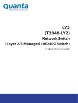
Connecting Power Cord Anti-Trip
1. Force the head of the xing strap tightly into the hole next
to the power socket until its buckled on the shell without
falling o.
In order to protect the power supply from accidental
disconnection, it’s recommended to use a power cord anti-trip
for installation.
Ground Terminal
Ground Cable
Ground Bar
2. After plugging the power cord into the power outlet, slide the
protector over the remaining strap until it slides over the end
of the power cord.
3. Wrap the strap of the protective cord around the power cord
and lock it tightly. Fasten the straps until the power cord is
securely fastened.
POWERING & CONNECTING
PORT CONNECTING
Connect to RJ45 Port
1. Connect one end of the network cable to the
switch, and the other end to the peer device.
2. After powered on, check the status of the
port indicator. If on, it means that the link is
connected normally; if o, it means the link is
disconnected, please check the cable and the
peer device whether is enabled.
Crystal head
Ethernet RJ45
RJ45
port
RJ45 port
Connect to SFP+ Port
The installation process of the ber module is as follows:
1. Grasp the ber module from the side and insert it smoothly along
the switch SFP+ port slot until the module is in close contact with
the switch.
2. When connecting, pay attention to conrm the Rx and Tx ports
of SFP+ ber module. Insert one end of the ber into the Rx and
Tx ports correspondingly, and connect the other end to another
device.
3. After powered on, check the status of the port indicator. If on,
it means that the link is connected normally; if o, it means the
link is disconnected, please check the cable and the peer device
whether is enabled.
Notes:
Please select the optical ber cable according to the module type. The multi-mode module corresponds to the
multi-mode optical ber, and the single-mode module corresponds to the single-mode optical ber.
Please select the same wavelength optical ber cable for connection.
Please select an appropriate optical module according to the actual networking situation to meet dierent
transmission distance requirements.
The laser of the rst-class laser products is harmful to eyes. Do not look directly at the optical ber connector.
Fiber
module
Connect to Console Port
1. Connect the console cable (prepared by yourself) to the DB9 male connector or USB port to the PC.
2. Connect the other end of the RJ45 end of the console cable to the console port of switch.
Rubber footpads
Circular groove
INSTALLATION
Install on the Desktop
1. Place the bottom of switch on a suciently
large and stable table.
2. Peel o the rubber protective paper of the
four footpads one by one, and stick them in
the corresponding circular grooves at the
four corners of the bottom of the case.
3. Flip the switch over and place it smoothly
on the table.
To connect, the steps order (1 -> 2) must be respected.
To disconnect, the steps order is reversed (2 -> 1).
Notes:
Connect to Console Port (DB9) Connect to Console Port (USB)
Install on a 19” Standard Rack
1. Check the grounding and stability of the
rack.
2. Install the two L-shaped rack-mounting
in the accessories on both sides of
switch, and x them with the screws
provided (KM 3*6).
3. Place the switch in a proper position in
the rack and support it by the bracket.
4. Fix the L-shaped rack-mounting to the
guide grooves at both ends of the rack
with screws (prepared by yourself) to
ensure that the switch is stable and
horizontally installed on the rack.
SFP+
Port
~ 5 ~
ACCESS & CONFIGURE
Method 1: Login using the Web UI
1. A PC uses a network cable to correctly connect any RJ45 port of the switch.
2. Set the Ethernet (or local connection) IP address of the PC to 192.168.0.x (“x” is any value between 1-253), and
the subnet mask to 255.255.255.0, so that it is in the same network segment with switch IP address. If DHCP is
used, this step could be skipped.
3. Type the switch’s management IP address http://<gwn7806(P)_IP> in the browser, and enter username and
password to login. (The default administrator username is “admin” and the default
random password can be found
at the sticker on the GWN7806(P) switch).
Note: If no DHCP server is available, the GWN7806(P) default IP address is 192.168.0.254.
Method 2: Login using the Console port
Method 3: Login Remotely using SSH/Telnet
1. Use the console cable to connect the console port of switch and the serial port of PC.
2. Open the terminal emulation program of PC (e.g. SecureCRT), enter the default username and password to login.
(The default administrator username is “admin” and the default random password can be found at the sticker on
the GWN7806(P) switch).
1. Turn on the Telnet of the switch.
2. Enter “cmd” in PC/Start.
3. Enter telnet <gwn7806(P)_IP> in the cmd window.
4. Enter the default username and password to login. (The default administrator username is “admin” and the default
random password can be found at the sticker on the GWN7806(P) switch).
Method 4: Congure using GWN.Cloud / GWN Manager
Type https://www.gwn.cloud (https://<gwn_manager_IP> for GWN Manager) in the browser, and enter the
account and password to login the cloud platform. If you don’t have an account, please register rst or ask the
administrator to assign one for you.
The GNU GPL license terms are incorporated into the device rmware and can be accessed
via the Web user interface of the device at my_device_ip/gpl_license. It can also be accessed
here: https://www.grandstream.com/legal/open-source-software To obtain a CD with GPL
source code information please submit a written request to: [email protected]
Refer to online documents and FAQ for more detailed information:
https://www.grandstream.com/our-products
Certification Regulatory Information
U.S. FCC Part 15 Regulatory Information
This device complies with part 15 of the FCC Rules. Operation is subject to the
following two conditions:(1) this device may not cause harmful interference,
and(2) this device must accept any interference received, including interference
that may cause undesired operation.
Any Changes or modifications not expressly approved by the party responsible
for compliance could void the user's authority to operate the equipment.
NOTE: This equipment has been tested and found to comply with the limits for
a Class A digital device, pursuant to part 15 of the FCC Rules. These limits are
designed to provide reasonable protection against harmful interference when
the equipment is operated in a commercial environment. This equipment
generates, uses, and can radiate radio frequency energy and, if not installed
and used in accordance with the instruction manual, may cause harmful
interference to radio communications. Operation of this equipment in a
residential area is likely to cause harmful interference in which case the user will
be required to correct the interference at his own expense.
Canada Regulatory Information
CAN ICES-003 (A)/NMB-003(A)
This product meets the applicable Innovation, Science and Economic
Development Canada technical specifications.
Le présent produit est conforme aux spécifications techniques applicables
d'Innovation, Sciences et Développement économique Canada.
EU Regulatory Information
Hereby, [Grandstream Networks, Inc.] declares that the equipment type
[GWN7806P] is in compliance with Directive 2014/30/EU&2014/35/EU.
The full text of the EU declaration of conformity is available at the following
internet address: www.grandstream.com
UK Regulatory Information
Hereby, [Grandstream Networks, Inc.] declares that the equipment
type [GWN7806P] is in compliance with UK SI 2016 No. 1091&2016 No. 1101.
The full text of the UK declaration of conformity is available at the following
internet address: www.grandstream.com
  • Page 1 1
  • Page 2 2
  • Page 3 3
  • Page 4 4
  • Page 5 5

Grandstream GWN7806 User manual

Type
User manual

Grandstream GWN7806 is an enterprise-grade managed network switch that offers scalable, secure, and high-performance networking solutions for small-to-medium businesses. With 48 Ethernet ports, 6 SFP+ ports, and advanced features like VLAN segmentation, QoS prioritization, and comprehensive security, the GWN7806 enables flexible traffic management, network optimization, and protection against potential cyber threats. It supports PoE/PoE+ output for powering IP phones, cameras, and Wi-Fi access points, simplifying installation and power management.

Ask a question and I''ll find the answer in the document

Finding information in a document is now easier with AI