Page is loading ...

Grandstream Networks, Inc.
GWN780x Series
GWN780x(P) L2+ – User Manual

WELCOME
The GWN780x series are Layer 2+ managed network switches that allow small-to-medium enterprises to build scalable,
secure, high-performance, and smart business networks that are fully manageable. It supports advanced VLAN for flexible and
sophisticated traffic segmentation, advanced QoS for prioritization of network traffic, IGMP Snooping for network
performance optimization, and comprehensive security capabilities against potential attacks. The PoE models provide smart
dynamic PoE output to power IP phones, IP cameras, Wi-Fi access points, and other PoE endpoints. The GWN7800 series can
be managed in a number of ways, including the local web user interface of the GWN7800 series switch. The series is also
supported by GWN.Cloud, Grandstream’s cloud and on-premise Wi-Fi management platform. The enterprise-grade GWN780x
series are the ideal managed network switches for small-to-medium businesses.
PRODUCT OVERVIEW
Technical Specifications
GWN7801 GWN7801P GWN7802 GWN7802P GWN7803 GWN7803P
Network
Protocol
IPv4, IPv6, IEEE 802.3, IEEE 802.3i, IEEE 802.3u, IEEE 802.3ab, IEEE 802.3z, IEEE 802.3x, IEEE 802.3af/at, IEEE
802.1p, IEEE 802.1Q, IEEE 802.1w, IEEE 802.1d, IEEE 802.1s
Gigabit
Ethernet Ports 8 16 24
Gigabit SFP
Ports 2 4
Console 1
Number of PoE
Ports / 8 /16 / 24
Integrated
Power Supply 30W 150W 30W 270W 30W 400W
Max Output
Power per PoE
Port
/ 30W / 30W / 30W
Max Total PoE
Output Power / 120W / 240W / 360W
PoE Standards / IEEE 802.3af/at / IEEE 802.3af/at / IEEE 802.3af/at
Auxiliary Ports 1x Reset Pinhole
Forwarding
Mode Store-and-forward
Total non-
blocking
throughput
10Gbps 20Gbps 28Gbps

Switching
Capability 20Gbps 40Gbps 56Gbps
Forwarding
Rate 14.88M packets per second 29.76M packets per second 41.66M packets per second
Packet Buffer 4.1MB
Switching
●8K static, dynamic and filtering MAC addresses
●4K VLANs, port-based VLAN, IEEE 802.1Q VLAN tagging, voice VLAN
●VLAN virtual interface
●8 link aggregation groups
●Spanning tree, 16 instances for MSTP
Multicast IGMP Snooping, MLD Snooping
QoS/ACL
●Auto detection and prioritization of voice/video/RTP/SIP/other latency-sensitive packets
●Port priority
●Priority mapping
●Queue scheduling, including SP, WRR
●Traffic shaping
●Rate limit
●1.5K ACL for Ethernet, IPv4 and IPv6
DHCP Option 82, 60,160 and 43
Maintenance CPU and memory monitoring, SNMP, RMON, LLDP&LLDP-MED, backup and restore, syslog, alert, diagnostics
including Ping, Traceroute, port mirroring
Security
●User hierarchical management and password protection, HTTPS, SSH, Telnet
●802.1X authentication
●AAA authentication including RADIUS, TACACS+
●Storm control
●Port isolation, port security, sticky MAC
●Filtering MAC address
●IP source guard, DoS attack prevention, ARP inspection
●DHCP Snooping
●Loop protection including BPDU proctection
●Kensington Security Slot (Kensington Lock) support
Mounting Desktop/ Wall-Mount Desktop, wall-mount, or rack-mount (rack-mount brackets included)
LEDs
1x tri-color LED for device tracking and status indication
10x green
LEDs for
data ports
10x green LEDs
for data ports, 8x
yellow-color
LEDs
for PoE ports
20x green
LEDs for
data ports
20x green LEDs
for data ports, 16x
yellow-color LEDs
for PoE ports
28x green
LEDs for
data ports
28x green LEDs
for data ports, 24x
yellow-color LEDs
for PoE ports
Fan / / / 1 / 2
Environmental Operation: 0°Cto 45°C, humidity 10-90% RH(Non-condensing)
Storage: -10°C to 60°C, humidity: 5% to 95%(Non-condensing)
Dimensions 300mm(L)*175mm(W)*44(H) 440mm(L)*200mm(W)*44mm(H)

GWN780x Technical Specifications
INSTALLATION
Before deploying and configuring the GWN780x switch, the device needs to be properly powered up and connected to the
network. This section describes detailed information on the installation, connection, and warranty policy of the GWN780x
switch.
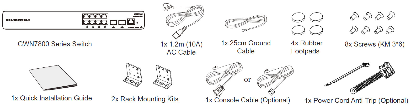
Package Contents
GWN780x Package Contents
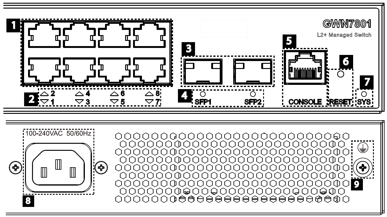
GWN780x Ports
GWN7801/GWN7801P
GWN7801/GWN7801P Ports
Unit
Weight(TBD) 1.8Kg 2Kg 2.6Kg 3Kg 2.7Kg 3.3Kg
Package
Content
Switch, 1x 1.2m(10A) AC Cable,
1x Ground Cable, 4x Rubber Feet,
2x Lug Ear
Switch, 1x 1.2m(10A) AC Cable, Rack-mounting Standard Brackets, 1x
Ground Cable, 4x Rubber Feet, 2x Lug Ear
Compliance FCC, CE, RCM, IC, UKCA
No. Port & LED Description
1 Port 1-8 8x Ethernet RJ45 (10/100/1000Mbps), used for connecting terminals. Note: GWN7801P
Ethernet ports support PoE and PoE+.
2 1-8 Ethernet ports’ LED indicators

GWN7801(P) Ports and LEDs
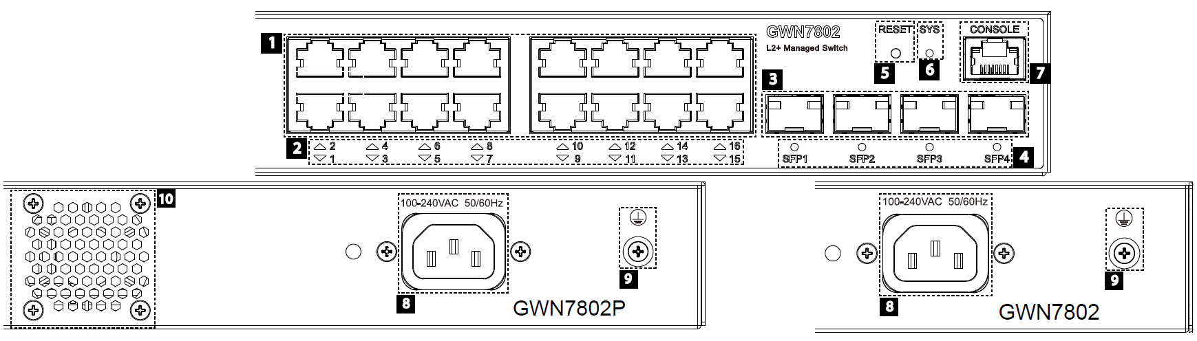
GWN7802/GWN7802P
GWN7802/GWN7802P Ports
GWN7802(P) Ports and LEDs
3 Port SFP1/2 2x 1000Mbps SFP ports
4 SFP 1/2 SFP ports’ LED indicators
5 CONSOLE 1x Console port, used for connecting managing PC
6 RESET Factory Reset pinhole. Press for 5 seconds to reset factory default settings
7 SYS System LED indicator
8 100-240 VAC 50-60Hz Power socket
9Lightning protection grounding post
No. Port & LED Description
1 Port 1-16 16x Ethernet RJ45 (10/100/1000Mbps), used for connecting terminals. Note: GWN7802P
Ethernet ports support PoE and PoE+.
2 1-16 Ethernet ports’ LED indicators
3 Port SFP1/2/3/4 4x 1000Mbps SFP ports
4 SFP 1/2/3/4 SFP ports’ LED indicators
5 RESET Factory Reset pinhole. Press for 5 seconds to reset factory default settings
6 SYS System LED indicator
7 CONSOLE 1x Console port, used for connecting managing PC
8 100-240 VAC 50-60Hz Power socket
9Lightning protection grounding post
10 Fan 1x Fan

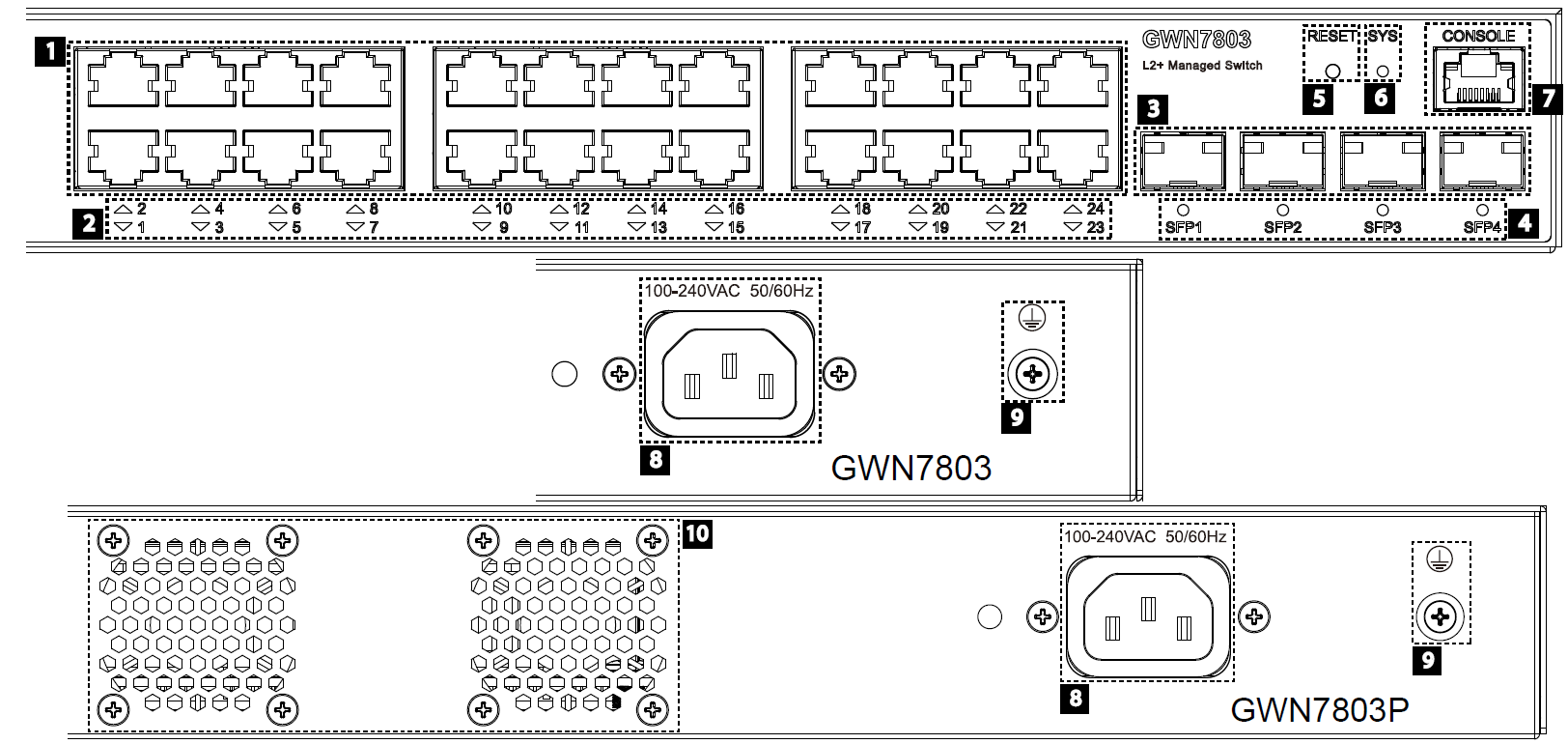
GWN7803/GWN7803P
GWN7803/GWN7803P Ports
GWN7803(P) Ports and LEDs
No. Port & LED Description
1 Port 1-24 24x Ethernet RJ45 (10/100/1000Mbps), used for connecting terminals. Note: GWN7803P
Ethernet ports support PoE and PoE+.
2 1-24 Ethernet ports’ LED indicators
3 Port SFP1/2/3/4 4x 1000Mbps SFP ports
4 SFP 1/2/3/4 SFP ports’ LED indicators
5 RESET Factory Reset pinhole. Press for 5 seconds to reset factory default settings
6 SYS System LED indicator
7 CONSOLE 1x Console port, used for connecting managing PC
8 100-240 VAC 50-60Hz Power socket
9Lightning protection grounding post
10 Fan 2x Fan

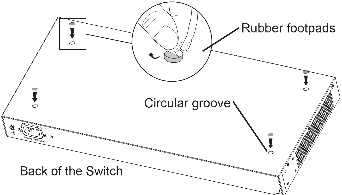
Install on the Desktop
GWN780x(P) Desktop Installation
1. Place the bottom of switch on a sufficiently large and stable table.
2. Peel off the rubber protective paper of the four footpads one by one, and stick them in the corresponding circular
grooves at the four corners of the bottom of the case.
3. Flip the switch over and place it smoothly on the table.
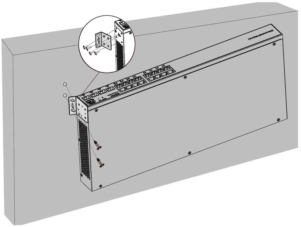
Install on the Wall
GWN780x(P) Wall Installation
1. Use the matching screws (KM 3*6) to fix the two L-shaped rack-mounting kits (rotated 90°) on both sides of switch.
2. Stick the switch port up and horizontally on the selected wall, mark the position of the screw hole on the L-shaped rack-
mounting kits with a marker. Then, drill a hole at the marked position with an impact drill, and drill the expansion
screws(prepared by yourself) into the drilled hole in the wall.
3. Use a screwdriver to tighten the screws (prepared by yourself) that have passed through the L-shaped rack-mounting kits
to tighten the expansion solenoids to ensure that the switch is firmly installed on the wall.

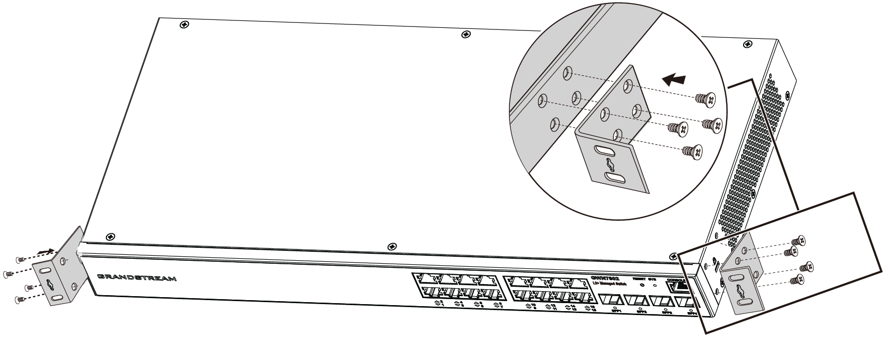
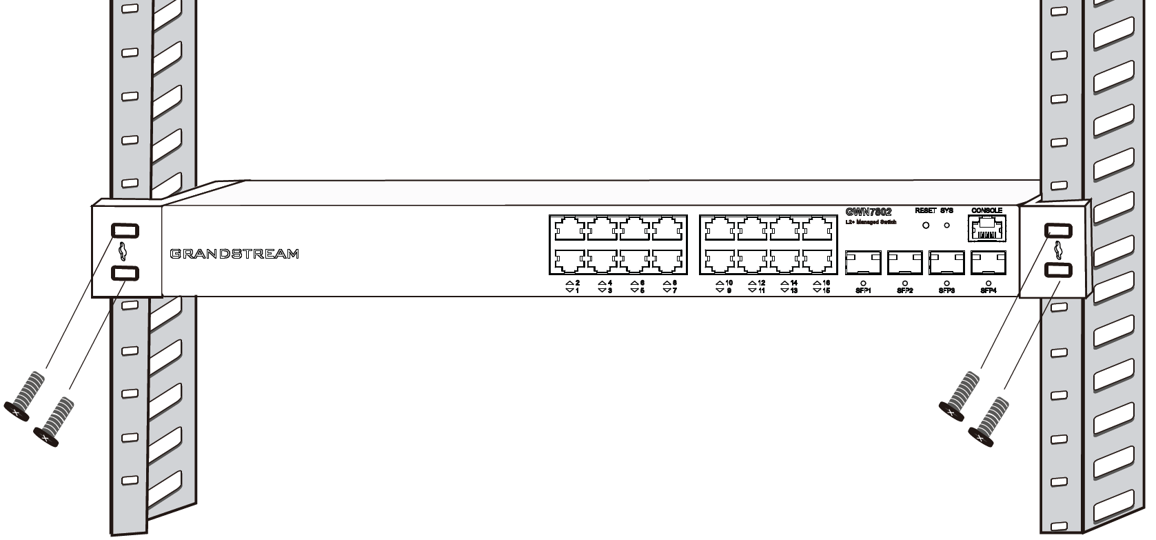
Install on a 19″ Standard Rack
GWN780x(P) L-shaped rack-mounting Installation
1. Check the grounding and stability of the rack.
2. Install the two L-shaped rack-mounting in the accessories on both sides of switch, and fix them with the screws provided
(KM 3*6).
GWN780x(P) Standard Rack Installation
3. Place the switch in a proper position in the rack and support it by the bracket.
4. Fix the L-shaped rack-mounting to the guide grooves at both ends of the rack with screws(prepared by yourself) to
ensure that the switch is stably and horizontally installed on the rack.
Powering and Connecting GWN780x(P)
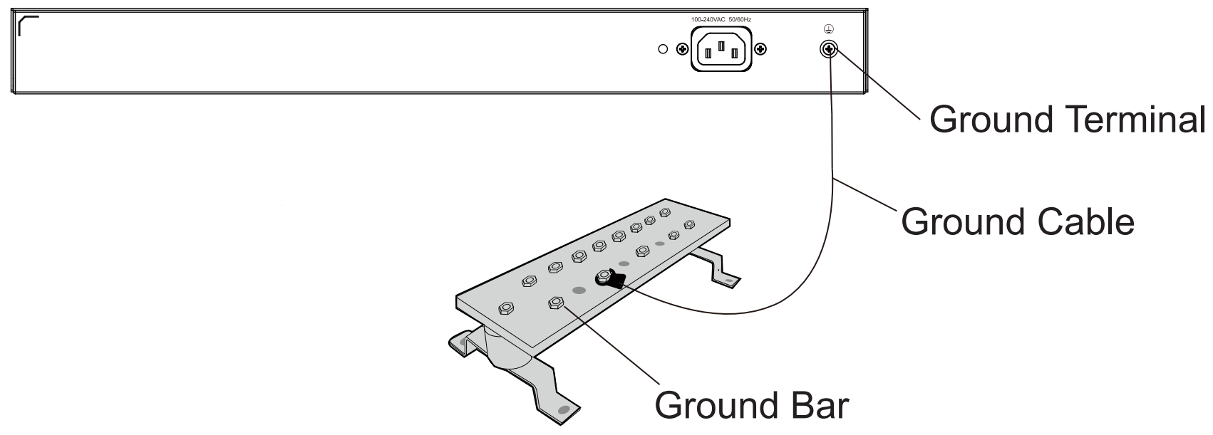
Grounding the Switch
Grounding the Switch
1. Remove the ground screw from the back of switch, and connect one end of the ground cable to the wiring terminal of
switch.

2. Put the ground screw back into the screw hole, and tighten it with a screwdriver.
3. Connect the other end of the ground cable to other device that has been grounded or directly to the terminal of the
ground bar in the equipment room.
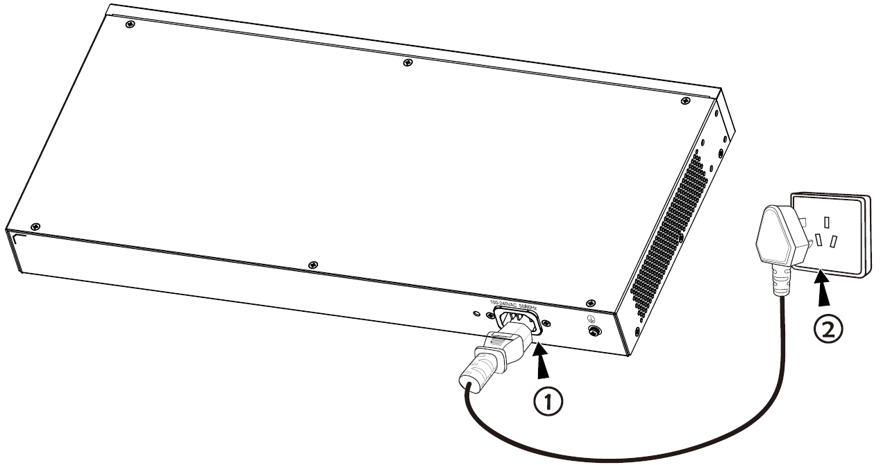
Powering on the Switch
Connect the power cable and the switch first, then connect the power cable to the power supply system of the equipment
room
Powering on the Switch
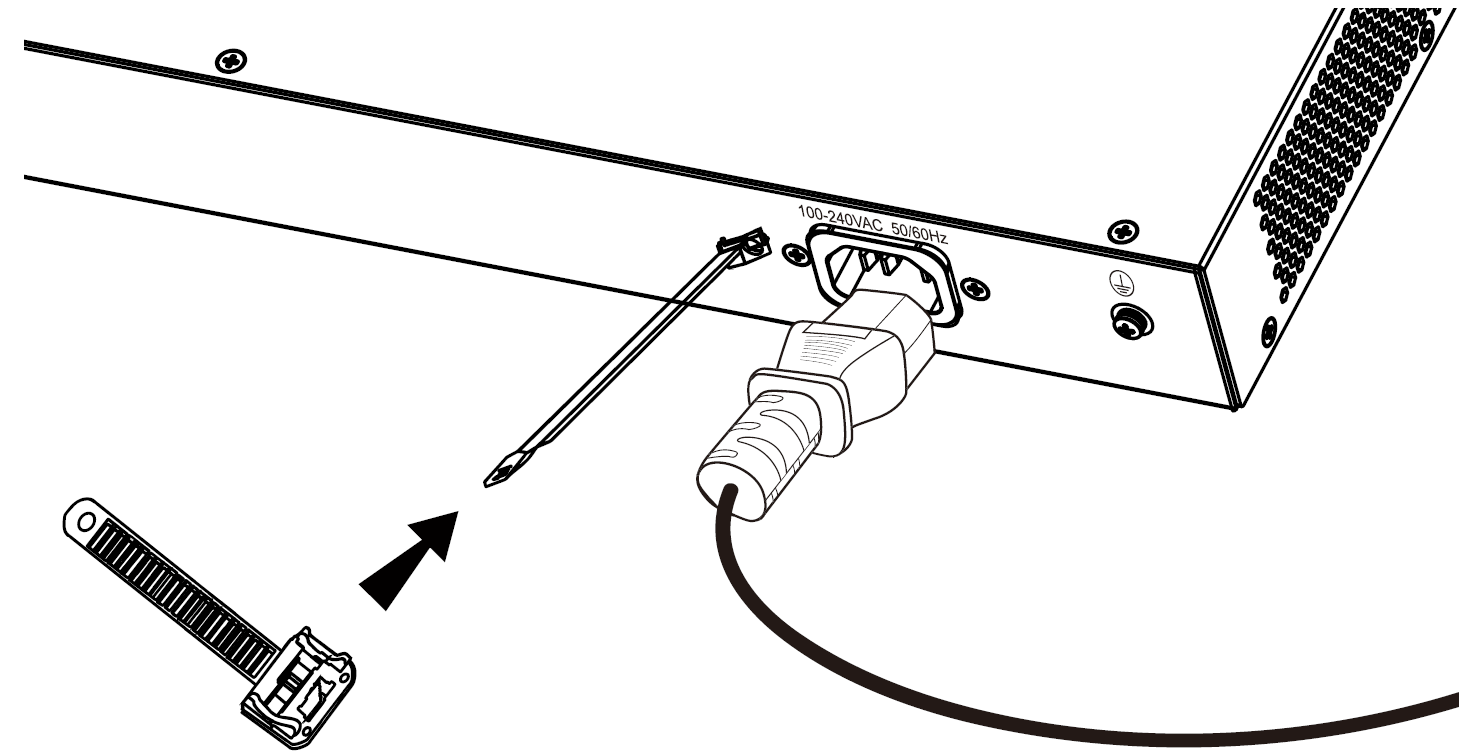
Connecting Power Cord Anti-Trip (Optional)
In order to protect the power supply from accidental disconnection, it’s recommended to purchase a power cord anti-trip for
installation.
Connecting Power Cord Anti-Trip (Optional) – part 1
1. Place the smooth side of the fixing strap towards the power outlet and insert it into the hole on the side of it.
Connecting Power Cord Anti-Trip (Optional) – part 2
2. After plugging the power cord into the power outlet, slide the protector over the remaining strap until it slides over the
end of the power cord.

3. Wrap the strap of the protective cord around the power cord and lock it tightly. Fasten the straps until the power cord is
securely fastened.
Connect to SFP Port
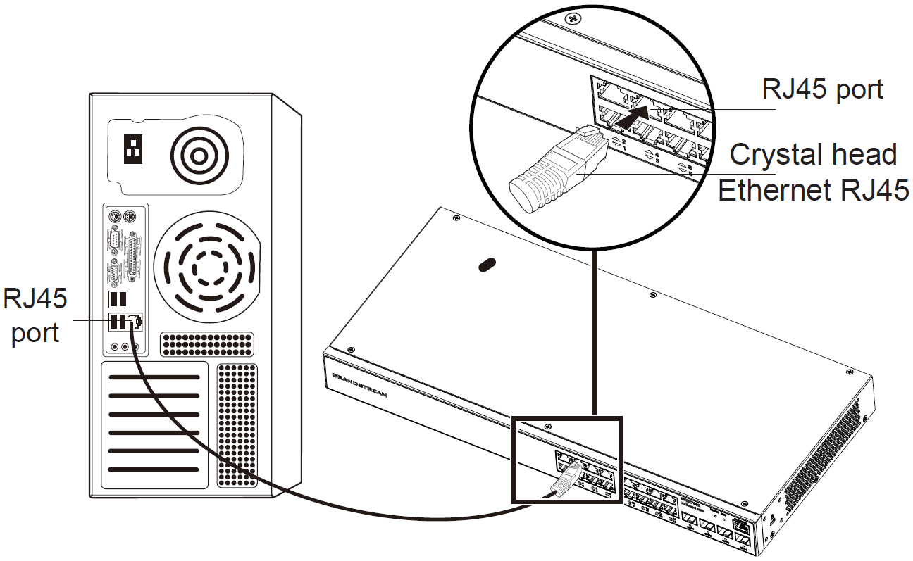
Connect to RJ45 Port
1. Connect one end of the network cable to the switch, and the other end to the peer device.
2. After powered on, check the status of the port indicator. If on, it means that the link is connected normally; if off, it means
the link is disconnected, please check the cable and the peer device whether is enabled.
Connect to Console Port
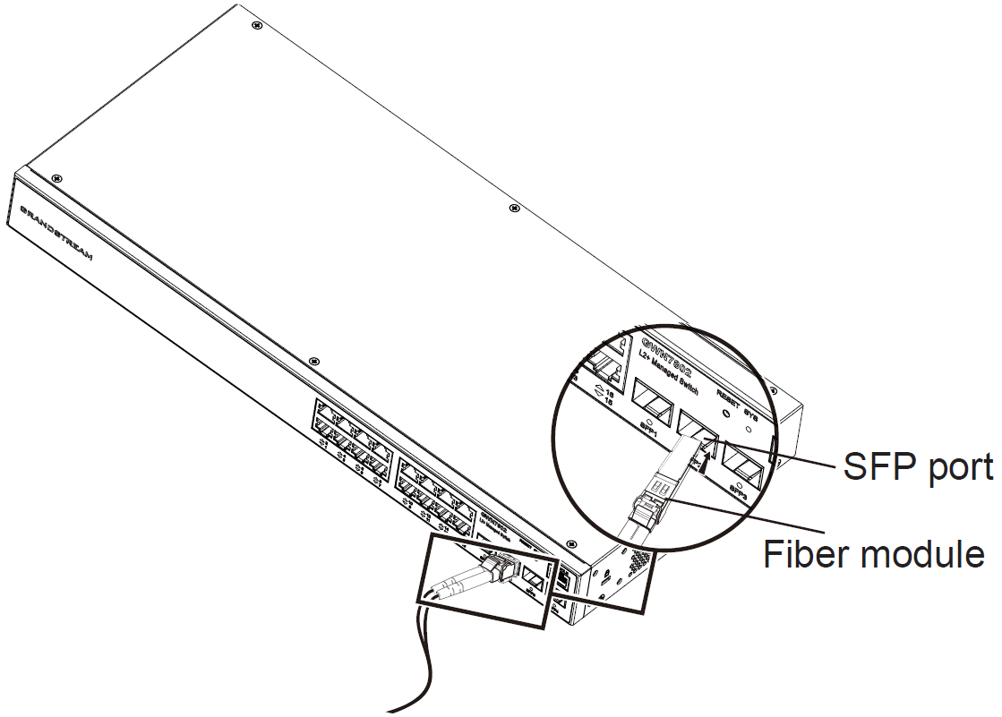
The installation process of the fiber module is as follows:
Connect to SFP Port
1. Grasp the fiber module from the side and insert it smoothly along the switch SFP port slot until the module is in close
contact with the switch.
2. When connecting, pay attention to confirm the Rx and Tx ports of SFP fiber module. Insert one end of the fiber into the Rx
and Tx ports correspondingly, and connect the other end to another device.
3. After powered on, check the status of the port indicator. If on, it means that the link is connected normally; if off, it means
the link is disconnected, please check the cable and the peer device whether is enabled.
Notes:
Please select the optical fiber cable according to the module type. The multi-mode module corresponds to the multi-mode
optical fiber, and the single-mode module corresponds to the single-mode optical fiber.
Please select the same wavelength optical fiber cable for connection.
Please select an appropriate optical module according to the actual networking situation to meet different transmission
distance requirements.
The laser of the first-class laser products is harmful to eyes. Do not look directly at the optical fiber connector.

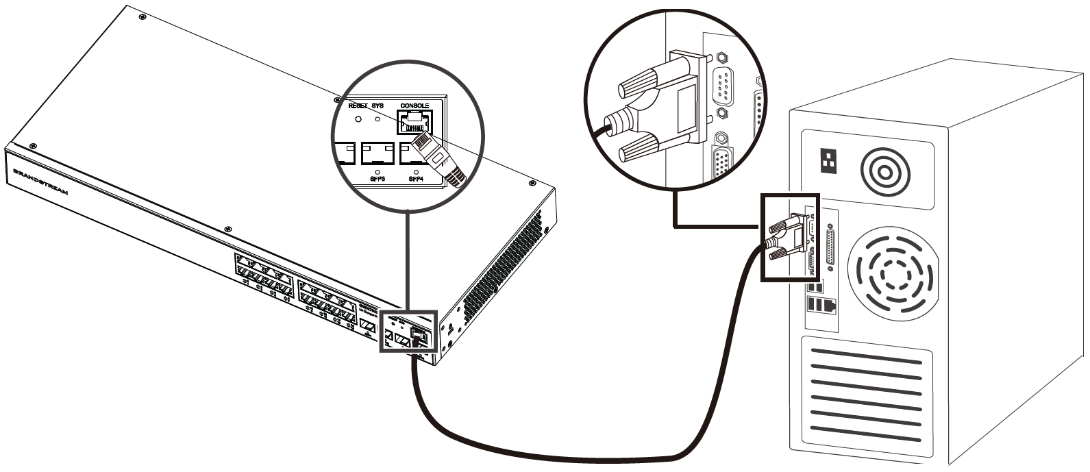
Connect to Console Port
Connect to Console Port
1. Connect the RJ45 end of the console cable to the console port of switch.
2. Connect the other end of the console cable to the DB9 male connector or USB port to the PC.
GETTING STARTED
LED Indicators
The front panel of the GWN780x(P) has LED indicators for power and interface activities, the table below describes the LED
indicators’ status.
Safety Compliances
The GWN780x(P) L2+ Managed Network Switch complies with FCC/CE and various safety standards. The GWN780x(P) power
adapter is compliant with the UL standard. Use the universal power adapter provided with the GWN780x(P) package only. The
manufacturer’s warranty does not cover damages to the device caused by unsupported power adapters.
Warranty
If GWN780x(P) L2+ Managed Network Switch was purchased from a reseller, please contact the company where the device was
purchased for replacement, repair or refund. If the device was purchased directly from Grandstream, contact our Technical
Support Team for an RMA (Return Materials Authorization) number before the product is returned. Grandstream reserves the
right to remedy the warranty policy without prior notification.
LED Indicator Status Description
System Indicator
Off Power off
Solid green Booting
Flashing green Upgrade
Solid blue Normal use
Flashing blue Provisioning
Solid red Upgrade failed
Flashing red Factory reset

GWN7803(P) LED Indicators
Access & Configure
Login using the Console port
1. Use the console cable to connect the console port of switch and the serial port of PC.
2. Open the terminal emulation program of PC (e.g. SecureCRT), enter the default username and password to login. (The
default administrator username is “admin” and the default random password can be found at the sticker on the GWN7800
switch).
Login Remotely using SSH
1. Enter “cmd” in PC/Start.
2. Enter ssh <gwn7800_IP> in the cmd window.
3. Enter the default username and password to login. (The default administrator username is “admin” and the default
random password can be found at the sticker on the GWN7800 switch).
Configure using GWN.Cloud
Type https://www.gwn.cloud in the browser, and enter the account and password to login the cloud platform. If you don’t
have an account, please register first or ask the administrator to assign one for you.
Login using the Web UI
The GWN780x(P) embedded Web server responds to HTTPS GET/POST requests. Embedded HTML pages allow users to
configure the device through a Web browser such as Microsoft IE, Mozilla Firefox, or Google Chrome.
Port Indicator
Off ●For all ports: port off
●For SFP ports: port failure
Solid green Port connected and there is no activity
Flashing green Port connected and data is transferring
Solid yellow Ethernet port connected, and there is no activity and PoE powered
Flashing yellow Ethernet port connected, data is transferring and PoE powered
Alternately flashing
yellow and green Ethernet port failure
Note:
If no DHCP server is available, the GWN7800 default IP address is 192.168.0.254.
Note:
The baud rate needs to be set to 115200.

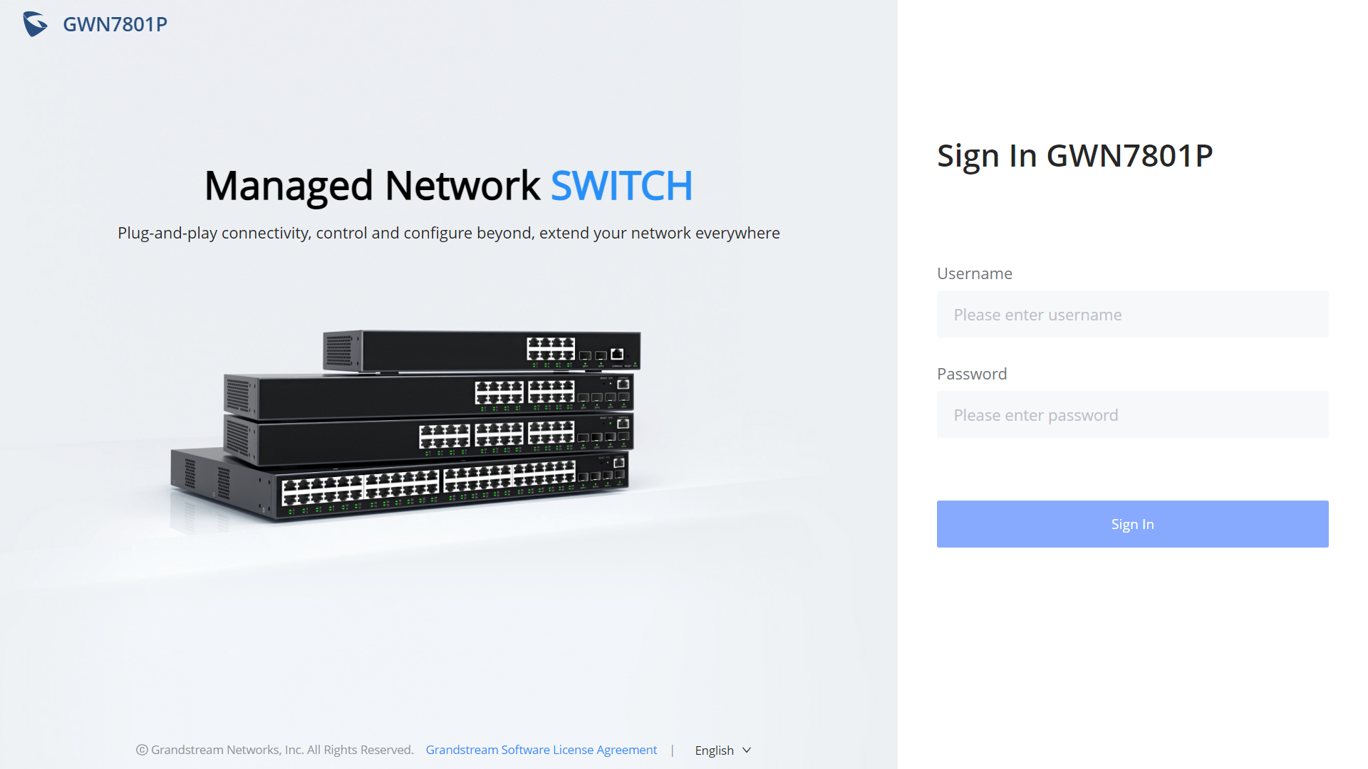
GWN780x(P) WEB GUI Page
1. A PC uses a network cable to correctly connect any RJ45 port of the switch.
2. Set the Ethernet (or local connection) IP address of the PC to 192.168.0.x (“x” is any value between 1-253), and the subnet
mask to 255.255.255.0, so that it is in the same network segment with switch IP address. If DHCP is used, this step could
be skipped.
3. Type the switch’s default management IP address http://<gwn7800_IP> in the browser, and enter username and
password to login. (The default administrator username is “admin” and the default random password can be found at the
sticker on the GWN7800 switch).
WEB GUI Languages
Currently, the GWN7800 web GUI supportsEnglishandSimplified Chinese.
To change the default language, select the displayed language at the bottom of the web GUI either before or after logging in.
Web GUI Languages – Login Page
WEB GUI – Start page
WEB GUI Configuration
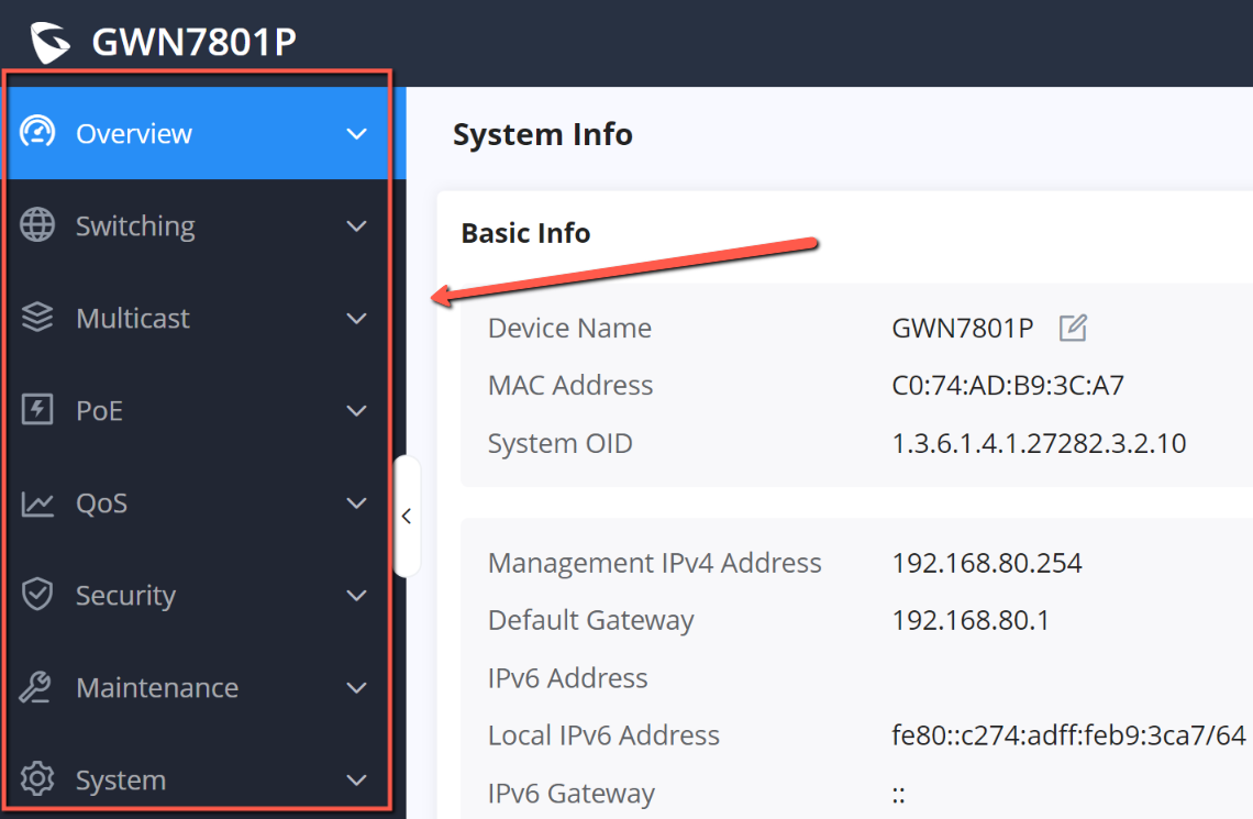
GWN7800 web GUI includes 8 main sections to configure and manage the switch and check the connection status.

WEB GUI Configuration
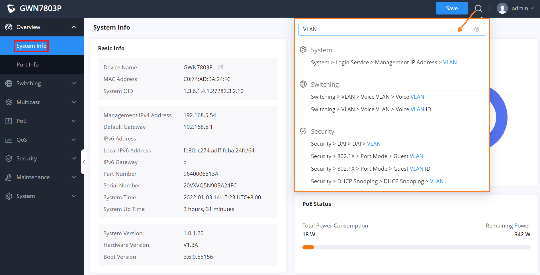
Search
In case it’s hard to go through every single section, GWN780x(P) Switches have search functionality to help the user find the
right configuration, settings or parameters, etc.
On the top of the page, there is a search icon, the user can click on it and then enter the keyword relevant to his search, then
he will get all the possible locations of that keyword.
Search
Overview Page
Overview is the first section that displays System information in the first page “System Info” and Port status on the second
page “Port Info”. This section provides the user with a general and global view about the GWN780x(P) system and ports
status for easy monitoring.
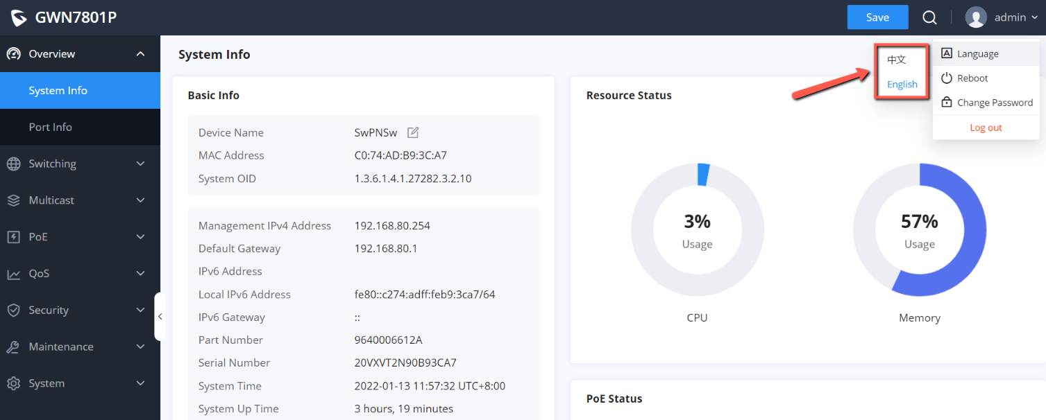
System Info
System Info is the first page after a successful login to the GWN780x(P) Web Interface. It provides an overall view of the
GWN780x(P) Switch information presented in a Dashboard style for easy monitoring including basic info, Resources Status,
PoE Status and System Events.
To name the device please click on , then enter the desired name.

System Info page
System Info page
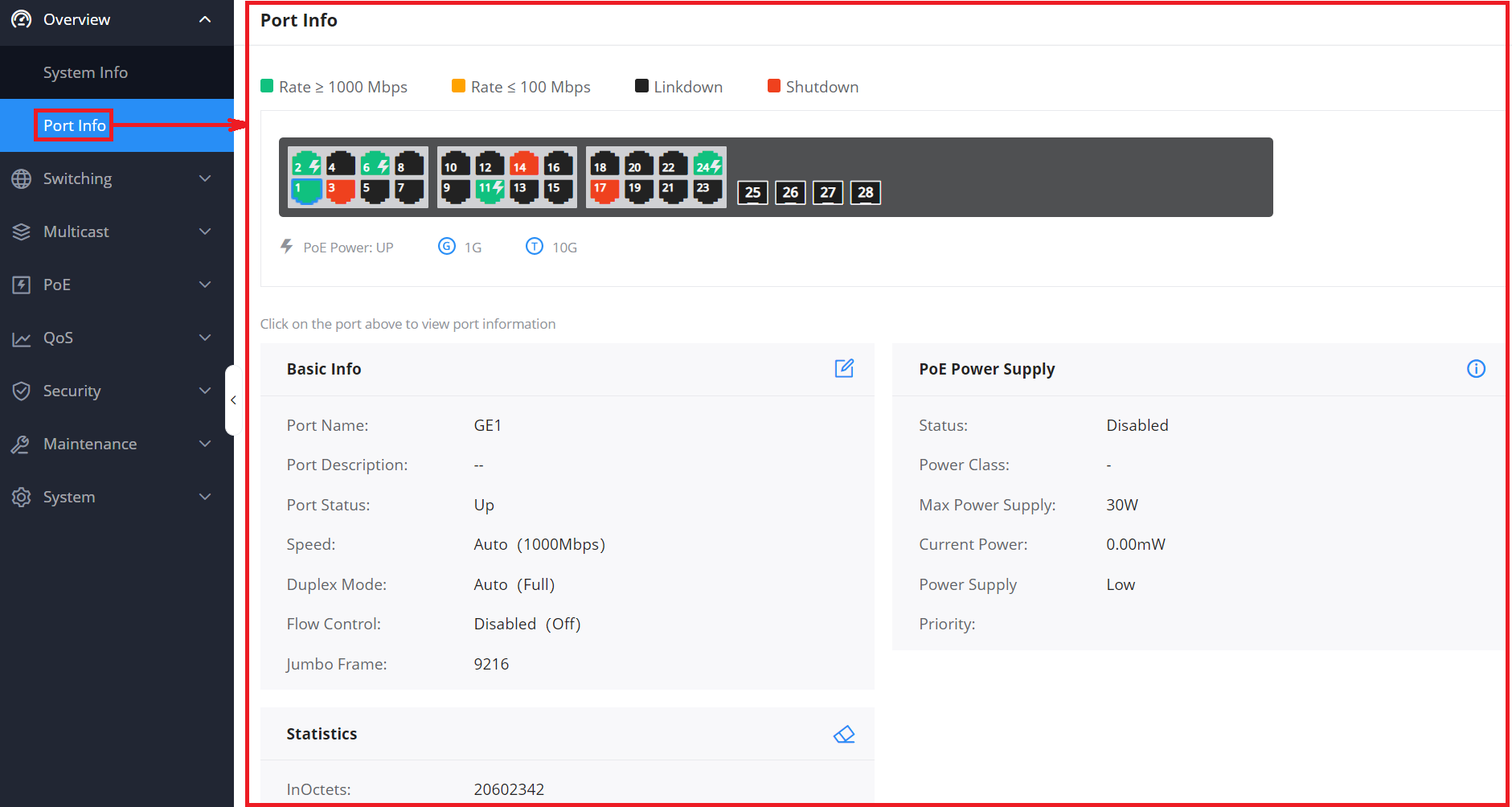
Port Info
This page displays the status for each port on the GWN780x(P) switches indicated by color code, in terms of connection (Up,
Linkdown or Shutdown), and also in terms of PoE (Up, Disabled, Current Power, priority etc).
Port Info page
The following table explained the color code and the symbols used:
Basic Info Displays Device and System general information that includes (Device name, MAC Address, Default
Gateway, System Time, System Version etc.)
Resource Status Displays in real time the usage of CPU and Memory.
PoE Status Shows the Total Power Consumption and the remaining Power in mA.
System Events Diplays the total number of events for each category (Emergency, Alert, Warning etc).
Note: Clicking on any events category will redirect you to the Diagnostics page for further details.
Ethernet Port is Down, PoE is Disabled
SFP Port is Down
Ethernet Port is Up, PoE is Disabled

Ports Labels and Color code
There are 3 main sections for each port:
Basic Info: displays info about the port name, speed, status etc.
Note: Click on to modify the port settings like Description, Speed, Duplex Mode and Flow Control or to enable or disable the
port.
PoE Power Supply: displays PoE Current Power and priority, Status etc.
Note: Click on to change PoE settings.
Statistics: displays Statistics about Octets, and different types of Packets (Broadcast, Multicast, etc).
Note: Click on to clear the statistics.
SWITCHING
Switching section is used to configure ports settings, link Aggregation, VLAN, Spanning Tree etc.
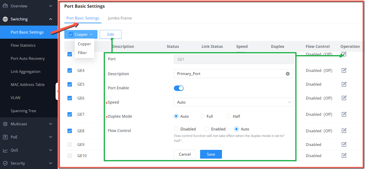
Port Basic Settings
On this page, you can configure the basic parameters for GWN780x(P) Switch ports, like disabling or enabling the port, adding
Description, specifying the speed by default is Auto, Duplex Mode, and Flow Control. There is also a filter on in case you wan
to edit only the Copper ports which are the Gigabit Ethernet ports or Fiber ports which are the SFP ports.
Port Basic Settings page
Ethernet Port is Up, PoE is Enabled
Ethernet Port is Shutdown, PoE is Disabled
PoE Power is UP
1 Gbps speed
10 Gbps speed
Port The selected Port to be configured, it can be either Gigabit Ethernet port or SFP port.

Port Basic Settings
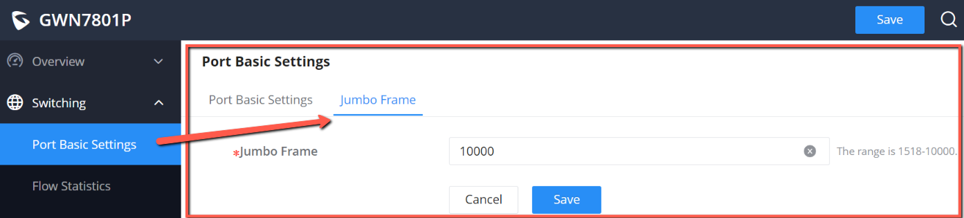
Jumbo Frame
The maximum Transmission Payload or MTU is typically 1500 bytes, in case the user requires even a bigger MTU length for a
specific scenario, there is an option on the GWN780x(P) Switch to enable Jumbo Frame, the maximum Ethernet frame size
ranges from 1518 up to 10000.
Jumbo Frame
Flow Statistics
For monitoring or even sometimes troubleshooting, the Flow Statistics displays in real time the flow of data with different
units like Octects, Packets, Transmission Rate and OurErrPackets. The option to clear all the statistics or a specific port is
supported as well.
Description
It is used to configure the information description of this interface , which can be a description of usage, etc., with a
maximum of 128 characters, and the characters limited to input are numbers 0-9 , letters az / AZ and special
characters.
Port Enable Set whether to enable the interface.
it is enabled by default.
Speed
Set the rate of the interface, the options are {Auto, 10Mbps, 100Mbps, 1000Mbps}.
The default is auto-negotiation.
Note: When set to Auto, the rate of the interface is automatically negotiated between the interface and the peer port
.
Duplex Mode
Set the duplex mode of the interface. The GE ports options are { auto-negotiation, full-duplex, half-duplex}.
The default is auto-negotiation.
Note: Optical ports only support full-duplex mode.
●Auto-negotiation: The duplex state of an interface is determined by the auto-negotiation between the interface
and the peer port.
●Duplex: the interface send and receive data packets.
●Half-duplex: interface can only send/ receive packets.
Flow Control
Set the flow control on the interface, the options are {Disabled, Enabled, Auto}. The default is Disabled.
After enabling it, if the local device is congested, it will send a message to the peer device to notify the peer device
to temporarily stop sending packets, after receiving the message, the peer device will temporarily stop sending
packets to the local and vice versa. Thus, the occurrence of packet loss is avoided.
Note: The optical port does not support auto-negotiation mode.

Flow Statistics
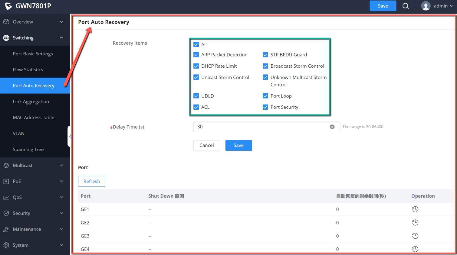
Port Auto Recovery
Port Auto Recovery helps recover a port after a specific delay that can be specified by the user. When the following functions
of the port trigger the port down, the port automatically returns to the up state after the delay time:
Examples:
ARP packet detection: If the ARP rate in DAI exceeds the set value, the current port will be shut down.
STP BPDU Guard: In spanning tree, the port enables BPDU Guard. When this function is triggered, the port will be shut
down.
Port Loop: When the port is self-looping and spanning tree is enabled, the port will be shut down.
ACL: When the ACL rule is matched and the action is shutdown, the port will be shut down.
Port Security: When the number of port MAC addresses exceeds the set number, the port will be shut down.
Port Auto Recovery
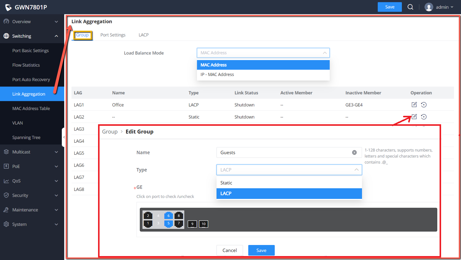
Link Aggregation
LAG means Link Aggregation Group which groups some physical ports together to make a single high-bandwidth data path.
Thus it can implement traffic load sharing among the member ports in a group to enhance the connection reliability.
Link Aggregation Group
There are two load balance modes on the GWN780x(P) Switches, either based on the MAC Address or based on the IP – MAC
Address. And in terms of the type of LAG, there are either the static option or to use the LACP or Link Aggregation Control
Protocol both of them are supported.
Note:
When the recovery time is up and the port is back up, if the condition that triggers the down occurs again, the port will be shut
down again.

Link Aggregation Group
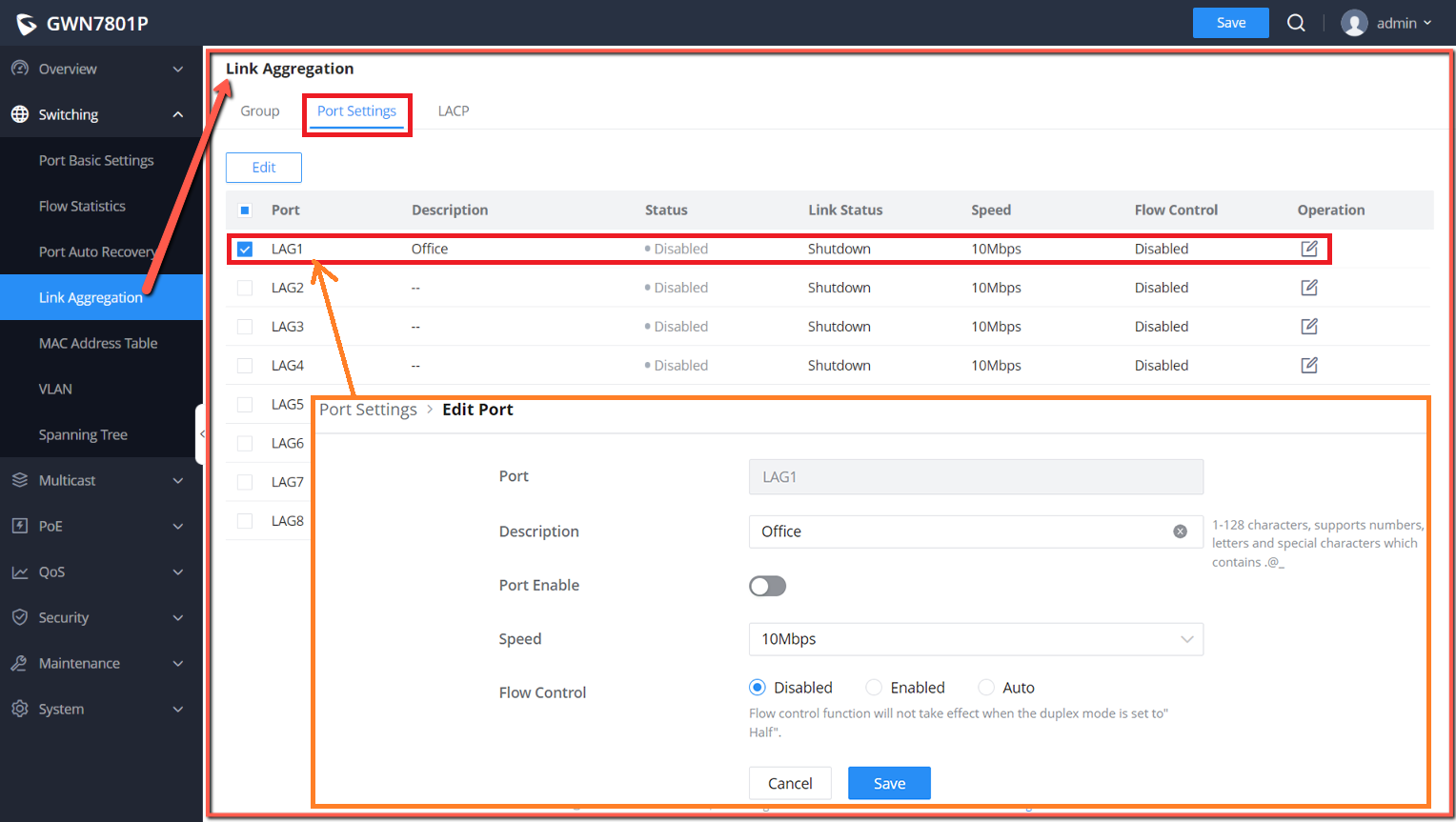
Link Aggregation Port
LAG Port Settings
In this page, the user can Enable the Link Aggregation Group and add Description as well as specifying the speed and the flow
control for LAG.
Link Aggregation – Port Settings
Load Balancing
Mode
Select your Load balance mode.
MAC address - Aggregated group will balance the traffic based on different MAC addresses. Therefore, the
packets from different MAC addresses will be sent to different links.
IP/Mac Address - Aggregated group will balance the traffic based on MAC addresses and IP addresses. Therefore,
the packets from same MAC addresses but different IP addresses will be sent to different links.
Edit Group
Name: Enter the name of the LA Group.
Type: Use the drop down menu to specify the type for LAG.
●Static- The static aggregated port sends packets over active member without detecting or negotiating with
remote aggregated port.
●LACP- The LACP aggregated ports place member into active only after negotiated with remote aggregated port
for best reliability.
GE: Click on port to check / uncheck which ones will be part of this LAG.
Port The selected LAG to be configured.
Description
It is used to configure the information description for this LAG , which can be a description of usage, etc., with a
maximum of 128 characters, and the characters limited to input are numbers 0-9 , letters az / AZ and special
characters.
Port Enable Set whether to enable the interface.
it is enabled by default.

Link Aggregation Settings
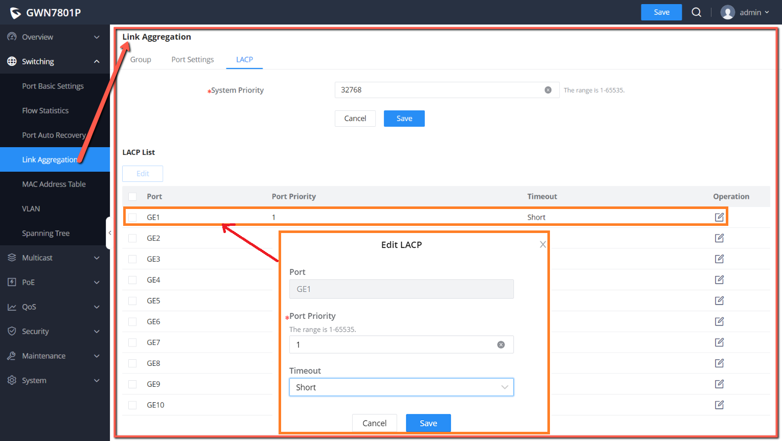
LACP
LACP or Link Aggregation Control Protocol is based on the priority, and the user can enable a system priority or even specify
the the priority for each port individually.
Link Aggregation – LACP
LACP
MAC Address Table
The MAC address table records the correspondence between the MAC addresses of other devices learned by the switch and
the interfaces, as well as information such as the VLANs to which the interfaces belong. When forwarding a packet, the device
queries the MAC address table according to the destination MAC address of the packet. If the MAC address table contains an
entry corresponding to the destination MAC address of the packet, it directly forwards the packet through the outbound
interface in the entry. If the MAC address table does not contain an entry corresponding to the destination MAC address of
the packet , the device will use broadcast mode to forward the packet on all interfaces in the VLAN to which it belongs except
the receiving interface.
The entries in the MAC address table are divided into Dynamic Address, Static MAC Address, Black hole Address and Port
Security Address.
Dynamic Address
Speed
Set the rate of the interface, the options are {Auto, 10Mbps, 100Mbps, 1000Mbps}.
The default is auto-negotiation.
Note: When set to Auto, the rate of the interface is automatically negotiated between the interface and the peer port
.
Flow Control
Set the flow control on the interface, the options are { Disabled, Enabled, Auto}. The default is Disabled
After enabling it, if the local device is congested, it will send a message to the peer device to notify the peer device
to temporarily stop sending packets, after receiving the message, the peer device will temporarily stop sending
packets to the local and vice versa. Thus, the occurrence of packet loss is avoided.
System Priority Set the system priority of LACP, the value range is an integer from 1-65535, the default is 32768.
Edit LACP
Port: Select the switch LAG interface to be configured
Port Priority:Set the LACP protocol priority of the port , the value range is an integer from 1 to 65535 , the default
is 1.
Note: The smaller the priority value of the port , the higher the LACP priority of the port.
Timeout: Set the timeout time for receiving LACP packets, the options are { Short, Long} , the default is Short.
●Short mode: the default timeout period for receiving LACP protocol packets is 3 seconds.
●Long mode: the default timeout period for receiving LACP protocol packets is 90 seconds .
/
