Page is loading ...

Variomat Basic
22.07.2020 - Rev.C
EN Operating Manual
Original operating manual

Contents
2 — English
Variomat Basic — 22.07.2020 - Rev.A
English
Variomat Basic
22.07.2020 - Rev.C
Contents
1 Notes on the operating manual ............................... 3
2 Liability and guarantee ........................................... 3
3 Safety ..................................................................... 3
3.1 Explanation of symbols .......................................................... 3
3.1.1 Symbols and notes used .......................................... 3
3.2 Personnel requirements ........................................................ 3
3.3 Personal protective equipment ............................................. 3
3.4 Intended use .......................................................................... 3
3.5 Inadmissible operating conditions ......................................... 3
3.6 Residual risks ......................................................................... 4
4 Description of the device ........................................ 4
4.1 Description ............................................................................ 4
4.2 Overview ............................................................................... 4
4.3 Identification ......................................................................... 4
4.3.1 Nameplate ............................................................... 4
4.3.2 Type code ................................................................ 5
4.4 Function ................................................................................. 5
4.5 Scope of delivery ................................................................... 5
4.6 Optional equipment and accessories ..................................... 5
5 I/O module (optional expansion module) ................ 6
5.1 Technical data........................................................................ 6
5.2 Settings .................................................................................. 6
5.2.1 Terminator settings in RS-485 networks .................. 6
5.2.2 Setting the analogue outputs .................................. 7
5.2.3 Module address setting ........................................... 8
5.2.4 I/O module default settings ..................................... 8
5.3 Replacing the fuses ................................................................ 9
6 Technical data ......................................................... 9
6.1 Control unit ........................................................................... 9
6.2 Tanks ................................................................................... 10
7 Installation ........................................................... 10
7.1 Installation conditions ......................................................... 10
7.2 Preparatory work ................................................................. 10
7.3 Execution ............................................................................. 10
7.3.1 Positioning ............................................................. 11
7.3.2 Installation of add-on components for the tanks... 11
7.3.3 Tank installation .................................................... 11
7.3.4 Hydraulic connection ............................................. 12
7.3.5 Fitting the thermal insulation ................................ 13
7.3.6 Fitting the level sensor........................................... 13
7.4 Switching and make-up variants .......................................... 14
7.4.1 Function ................................................................. 14
7.5 Electrical connection ........................................................... 15
7.5.1 Terminal diagram .................................................. 15
7.5.2 RS-485 interface .................................................... 16
7.6 Installation and commissioning certificate .......................... 16
8 Commissioning ...................................................... 16
8.1 Checking the requirements for commissioning ................... 16
8.2 Variomat switching points .................................................. 17
8.3 Modifying the controller's start routine .............................. 17
8.4 Filling the tanks with water ................................................. 18
8.4.1 Filling with a hose .................................................. 18
8.4.2 Filling with the solenoid valve in the make-up ...... 18
8.5 Venting the pump ............................................................... 18
8.6 Parametrising the controller in the Customer menu........... 18
8.7 Starting Automatic mode .................................................... 20
9 Operation .............................................................. 20
9.1 Automatic mode ................................................................. 20
9.2 Manual mode ...................................................................... 21
9.3 Stop mode ........................................................................... 21
9.4 Summer operation .............................................................. 21
9.5 Restarting ............................................................................ 21
10 Controller .............................................................. 22
10.1 Operator panel .................................................................... 22
10.2 Configuring settings in the controller .................................. 22
10.2.1 Service menu ......................................................... 22
10.2.2 Default settings ..................................................... 22
10.3 Messages ............................................................................ 22
11 Maintenance ......................................................... 24
11.1 Maintenance schedule ........................................................ 24
11.1.1 Cleaning the dirt trap ............................................ 25
11.1.2 Cleaning the tanks ................................................. 25
11.2 Checking switching points ................................................... 25
11.3 Inspection ........................................................................... 26
11.3.1 Pressure-bearing components .............................. 26
11.3.2 Inspection prior to commissioning ........................ 26
11.3.3 Inspection intervals ............................................... 26
12 Disassembly ........................................................... 26
13 Annex .................................................................... 27
13.1 Reflex Customer Service ..................................................... 27
13.2 Conformity and standards ................................................... 27
13.3 Guarantee ........................................................................... 27

Notes on the operating manual
Variomat Basic — 22.07.2020 - Rev.A
English — 3
1 Notes on the operating manual
This operating manual is an important aid for ensuring the safe and
reliable functioning of the device.
Reflex Winkelmann GmbH accepts no liability for any damage resulting
from failure to observe the information in this operating manual. In
addition to the requirements set out in this operating manual, national
statutory regulations and provisions in the country of installation must
also be complied with (concerning accident prevention, environment
protection, safe and professional work practices, etc.).
This operating manual describes the device with basic equipment and
interfaces for optional equipment with additional functions.
Notice!
Every person installing this equipment or performing any other
work at the equipment is required to carefully read this
operating manual prior to commencing work and to comply
with its instructions. The manual is to be provided to the
product operator and must be stored near the product for
access at any time.
2 Liability and guarantee
The device has been built according to the state of the art and
recognised safety rules. Nevertheless, its use can pose a risk to life and
limb of personnel or third persons as well as cause damage to the
system or other property.
It is not permitted to make any modifications at the device, such as to
the hydraulic system or the circuitry.
The manufacturer shall not be liable nor shall any warranty be
honoured if the cause of any claim results from one or more of the
following causes:
• Improper use of the device.
• Unprofessional commissioning, operation, service, maintenance,
repair or installation of the device.
• Failure to observe the safety information in this operating manual.
• Operation of the device with defective or improperly installed
safety/protective equipment.
• Failure to perform maintenance and inspection work according to
schedule.
• Use of unapproved spare parts or accessories.
Prerequisite for any warranty claims is the professional installation and
commissioning of the device.
Note!
Arrange for Reflex Customer Service to carry out commissioning
and annual maintenance, see chapter 13.1 "Reflex Customer
Service" on page 27 .
3 Safety
3.1 Explanation of symbols
3.1.1 Symbols and notes used
The following symbols and signal words are used in this operating
manual.
DANGER
Danger of death and/or serious damage to health
• The sign, in combination with the signal word 'Danger',
indicates imminent danger; failure to observe the safety
information will result in death or severe (irreversible) injuries.
WARNING
Serious damage to health
• The sign, in combination with the signal word 'Warning',
indicates imminent danger; failure to observe the safety
information can result in death or severe (irreversible) injuries.
CAUTION
Damage to health
• The sign, in combination with the signal word 'Caution',
indicates danger; failure to observe the safety information can
result in minor (reversible) injuries.
ATTENTION
Damage to property
• The sign, in combination with the signal word 'Attention',
indicates a situation where damage to the product itself or
objects within its vicinity can occur.
Note!
This symbol, in combination with the signal word 'Note',
indicates useful tips and recommendations for efficient handling
of the product.
3.2 Personnel requirements
Assembly, commissioning and maintenance as well as connection of the
electrical components may only be carried out by knowledgeable and
appropriately qualified electricians.
3.3 Personal protective equipment
Use the prescribed personal protective equipment as required (e.g. ear
protection, eye protection, safety shoes, helmet, protective clothing,
protective gloves) when working on the system.
Information on personal protective equipment requirements is set out
in the relevant national regulations of the respective country of
operation.
3.4 Intended use
The device is a pressure maintaining station for heating and cooling
water systems. It is intended to maintain the water pressure and to add
water within a system. The devices may be used only in systems that
are sealed against corrosion and with the following water types:
• Non-corrosive
• Chemically non-aggressive
• Non-toxic
The ingress of atmospheric oxygen by permeation into the entire
heating and cooling water system, make-up water and similar must be
reliably minimised during operation.
3.5 Inadmissible operating conditions
The device is not suitable for the following applications:
• Mobile system operation.
• Outdoor operation.
• For use with mineral oils.
• For use with flammable media.
• For use with distilled water.
Note!
It is not permitted to make any modifications to the hydraulic
system or the circuitry.

Description of the device
4 — English
Variomat Basic — 22.07.2020 - Rev.A
3.6 Residual risks
This device has been manufactured to the current state of the art.
However, some residual risk cannot be excluded.
CAUTION
Risk of burns on hot surfaces
Hot surfaces in heating systems can cause burns to the skin.
• Wear protective gloves.
• Please place appropriate warning signs in the vicinity of the
device.
CAUTION
Risk of injury due to pressurised liquid
If installation, removal or maintenance work is not carried out
correctly, there is a risk of burns and other injuries at the connection
points, if pressurised hot water or hot steam suddenly escapes.
• Ensure proper installation, removal or maintenance work.
• Ensure that the system is de-pressurised before performing
installation, removal or maintenance work at the connection
points.
WARNING
Risk of injury due to heavy weight
The devices are heavy. Consequently, there is a risk of physical injury
and accidents.
• Use suitable lifting equipment for transportation and
installation.
4 Description of the device
4.1 Description
The Variomat VS 1 is a pump-controlled pressure maintaining, make-up
and degassing station for heating and cooling water systems. The
Variomat is essentially a controller with pumps and at least one
expansion tank. The expansion tank is fitted with a diaphragm to divide
the tank into an air space and a water space. preventing the ingress of
atmospheric oxygen into the expansion water.
The Variomat VS 1 provides the following safety features:
• Optimisation of all pressure maintaining, degassing and make-up
processes.
– No direct intake of air thanks to a regulation of the pressure
maintenance with automatic make-up.
– No circulation issues caused by free bubbles in the circuit
water.
– Reduced corrosion damage due to oxygen removal from fill
and make-up water.
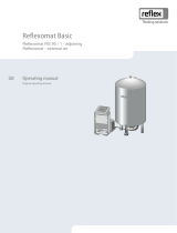
4.2 Overview
1
"VE" ventilation
6
Pump "PU"
2
Degassing valve "DV"
7
Feed and drain cock "FD"
3
"PIS" pressure transducer
8
"LIS" level sensor
4
"PV" overflow valve
WC
Make-up connection
5
“WV” make-up valve
EC
Degassing connection
4.3 Identification
4.3.1 Nameplate
The nameplate provides information about the manufacturer, the year
of manufacture, the manufacturing number and the technical data.
Information on the type plate
Meaning
Type
Device name
Serial No.
Serial number
min. / max. allowable pressure
P
Minimum/maximum permissible
pressure
max. continuous operating
temperature
Maximum temperature for
continuous operation
min. / max. allowable
temperature / flow
temperature TS
Minimum / maximum permissible
temperature / TS flow temperature
Year built
Year of manufacture
min. operating pressure set up
on shop floor
Factory set minimum operating
pressure
at site
Set minimum operating pressure
max. pressure saftey valve
factory - aline
Factory set actuating pressure of
the safety valve
at site
Set actuating pressure of the safety
valve

Description of the device
Variomat Basic — 22.07.2020 - Rev.A
English — 5
4.3.2 Type code
No.
Type code (example)
1
Control unit
designation
2
Number of pumps
Variomat VS 1, VG 500 l, VF 500 l
3
"VG" primary tank
1
2
3
4
5
6
4
Nominal volume
5
"VF" secondary
tank
6
Nominal volume
4.4 Function
1
Heating system
WV
Make-up valve
2
"MAG" expansion
vessel
PIS
Pressure sensor
3
Reflex Fillset Impulse
PV
Overflow valve (motor ball
valve)
4
Control unit
PU
Pump (pressurisation)
5
Hydraulic inlets
SV
Safety valve
6
Primary vessel air
space
EC
Expansion pipe
7
Secondary vessel air
space
FD
Feed and drain cock
ST
Dirt trap
LIS
Pressure load cell
FQIRA+
Contact water meter
DV
Degassing valve
WC
Make-up pipe
VE
Ventilation
Expansion vessel
One primary vessel and multiple optional secondary vessels may be
connected. A membrane separates the vessels into an air and a water
space, preventing the penetration of atmospheric oxygen into the
expansion water. The "VE" line connects the air space with the
atmosphere. The primary vessel is hydraulically flexibly connected to
the control unit. The function of the "LIS" level measuring using a
pressure pick-up is thus ensured.
Control unit
The control unit contains the hydraulic system and the controller. The
"PIS" pressure transducer records the pressure and the "LIS" pressure
pick-up registers the level; both values are displayed at the controller.
Pressurisation
The pressure in the system rises when the water is heated. When the
pressure set at the controller is exceeded, the "PV" overflow valve
opens and drains water from the system into the primary vessel, using
the "EC" expansion line. The pressure within the system drops. The
pressure in the facility system drops when the water cools. When the
pressure drops below the set value, the "PU" pump is activated and
uses the "EC" expansion pipe to transport water from the primary
vessel back into the system. The pressure in the facility system rises.
The controller ensures that the pressure is maintained, further
supported by the stabilisation provided by the "MAG" pressure
expansion vessel.
Degassing
Two "EC" expansion lines are required to degas the system water. One
pipe is intended for gas-rich water from the system, while one return
pipe returns the degassed water to the system. During the degassing
action, the "PU" pump and the "PV" overflow valve are in operation.
This transports a gas-rich partial flow of the system water V through the
de-pressurised primary vessel. Atmospheric pressure is used to separate
the free and dissolved gases and to discharge them through the "DV"
degassing valve. The controller ensures the hydraulic equalisation by
regulating the stroke of the "PV" overflow valve (motor ball valve). This
process can be applied in three different variants (continuous, interval
or run-on degassing).
Make-up
When the water level in the primary vessel falls below the minimum,
the "WV" make-up valve opens until the set level is again reached.
During the make-up process, the number of requests, the time and the
make-up time within a cycle are monitored. Using a FQIRA+ contact
water meter, the system monitors each individual make-up quantity
and the overall make-up quantity.
4.5 Scope of delivery
The scope of delivery is described in the shipping document and the
content is shown on the packaging. Immediately after receipt of the
goods, please check the shipment for completeness and damage. Please
notify us immediately of any transport damage.
Basic pressurisation equipment:
• The device on a pallet.
– Control unit and "VG" primary tank.
– Primary tank with accessories are packed on the tank base.
• "VE" aeration and de-aeration
• "DV" degassing valve
• Reducing sleeve
• "LIS" pressure pick-up
– Plastic sleeve with operating manual.
4.6 Optional equipment and accessories
The following optional equipment and accessories are available for this
device:
• Heat insulation for the primary vessel
• Secondary vessels
– Accessories are packed on the vessel mounting
• "VE" ventilation
• "DV" degassing valve
• Reducing coupling
• Additional equipment with unsupervised-operation BOB-pipe for
“TAZ+” temperature limiter
• Fillset for make-up with water.
– Fillset with integrated system isolator, water meter, dirt trap,
and locking mechanisms for the "WC" make-up pipe.
• Fillset Impulse with FQIRA+ contact water meter for make-up with
water.
• Servitec for make-up and degassing.
• Fillsoft for softening the make-up water from the potable water
supply system.
– The Fillsoft is installed between the Fillset and the device. The
device controller evaluates the make-up quantities and
signals the required replacement of the softening cartridges.
• Enhancements for the device controller:
– I/O modules for standard communication, see chapter 5.1
"Technical data" on page 6 .

I/O module (optional expansion module)
6 — English
Variomat Basic — 22.07.2020 - Rev.A
– Communication module for external operation of the
controller
– Master-Slave-Connect for master controllers for maximum 10
devices.
– Combined switching to increase capacity and parallel
switching of 2 hydraulically directly connected systems
– Bus modules:
• Profibus DP
• Ethernet
• Diaphragm rupture monitor.
Note!
Separate operating instructions are supplied with accessories.
5 I/O module (optional expansion module)
The I/O module is connected and wired in the factory.
It is used to expand the inputs and outputs of the Control Basic
controller.
The I/O module has two isolating amplifiers for analogue signals:
• Pressure measurement
• Level sensor
Six digital inputs and six digital outputs are used to process messages
and alarms:
Inputs
Three inputs, N.C. with 24 V self potential for standard settings.
• External temperature monitoring
• Minimum pressure signal
• Manual make-up of water
Three inputs, N.O. with 230 V self potential for standard settings.
• Emergency-Off
• Manual operation (e.g. for pump or compressor)
• Manual operation for the overflow
Outputs
Potential-free as changeover contacts. Default settings for messages:
• Make-up fault
• Below minimum pressure
• Above maximum pressure
• Manual or Stop operation
Note!
• For the default settings of the I/O modules, see
chapter 5.2.4 "I/O module default settings" on page 8
• All digital inputs and outputs can be set freely as option.
Settings to be made by Reflex Customer Service, see
chapter 13.1 "Reflex Customer Service" on page 27
5.1 Technical data
Housing
Plastic housing
Width (W):
340 mm
Height (H):
233.6 mm
Depth (D):
77 mm
Weight:
2.0 kg
Permissible operating
temperature:
-5 °C – 55 °C
Permissible storage temperature:
-40 °C – 70 °C
Degree of protection IP:
IP 64
Power supply:
230 V AC, 50 – 60 Hz (IEC 38)
Fuse (primary):
0.16 A time-lag
Input/output
• 6 floating relay outputs (changeover)
• 3 digital inputs 230 V AC
• 3 digital inputs 24 V AC
• 2 analogue outputs, to be set using jumpers
• 0 V – 1 V or 2 V – 10 V
• 0 mA – 20 mA or 4 mA – 20 mA
Interfaces to the controller
• RS-485
• 19.2 kbit/s
• Floating
• connection with plug or screw terminals
• RSI-specific protocol
5.2 Settings
GEFAHR
Danger to life from electric shock!
Risk of serious injury or death due to electric shock. Some parts of
the main board may still be at a voltage of 230 V even after the
mains plug has been pulled out.
• Before you remove the covers, completely isolate the device
controller from the power supply.
• Verify that the main circuit board is voltage-free.
5.2.1 Terminator settings in RS-485 networks
Examples for the activation and deactivation of terminators in RS–485
networks.
• The main circuit board of the Control Basic provides either the DIP
switches 1 and 2 or the jumper J3.
• Maximum length for an RS–485 connection is 1000 metres
Device controller with I/O module
1
Relay outputs of the I/O
module
• 6 digital outputs
• 2 analogue outputs
4
"Control Basic" controller
5
RS-485 connection
2
I/O module
6
Optional RS-485
connection
• Master - Slave
• Field bus
3
Connections of the I/ O
conductors

I/O module (optional expansion module)
Variomat Basic — 22.07.2020 - Rev.A
English — 7
Terminator settings
Jumper / Switch
Settings
I/O module
Control Basic
Jumper J10
Activated
X
---
and J11
Deactivated
---
---
DIP switch 1
Activated
---
X
and 2
Deactivated
---
---
Jumper J3
1 and 2 as well
as
Activated
---
X
3 and 4
Deactivated
---
---
Device controller with I/O module and bus module
1
I/O module
3
"Control Basic" controller
2
Bus module
Terminator settings
Jumper /
Switch
Settings
I/O module
Control
Basic
Bus module
Lon Works
Profibus DP
Ethernet
Jumper
J10
Activated
---
---
---
and J11
Deactivated
X
---
---
DIP
switch 1
Activated
---
X
---
and 2
Deactivated
---
---
---
Jumper J3
1 and 2 as
well as
Activated
---
X
X
3 and 4
Deactivated
---
---
---
Device controllers and I/O module in Master-Slave function
1
Control Basic controller in
Master function
3
Control Basic controller in
Slave function
2
I/O module for the Master
function
4
I/O module for the Slave
function
Master function
Terminator settings
Jumper /
Switch
Settings
I/O module
Control Basic
Jumper J10
Activated
X
---
and J11
Deactivated
---
---
DIP switch 1
Activated
---
X
and 2
Deactivated
---
---
Jumper J3
1 and 2 as
well as
Activated
---
X
3 and 4
Deactivated
---
---
Slave function
Terminator settings
Jumper /
Switch
Settings
I/O
module
I/O module
for
expansion
Control
Basic
Jumper J10
Activated
---
X
---
and J11
Deactivated
X
---
---
DIP switch 1
Activated
---
---
X
and 2
Deactivated
---
---
---
Jumper J3
1 and 2 as
well as
Activated
---
---
X
3 and 4
Deactivated
---
---
---
5.2.2 Setting the analogue outputs
Setting of the analogue outputs on the I/O module's main circuit board
1
Jumper J5
2
Jumper J6
Use the jumpers J5 and J6 to set both analogue outputs as current
outputs.
Proceed as follows:
1. Pull out the mains plug of the I/O module.
2. Open the housing cover.
3. Plug the jumpers in the required position.
Analogue
outputs
Jumper settings
Current output*
0 – 20 mA or
4 – 20 mA
Voltage output
0 - 10 V or
2 - 10 V
Analogue
output 1
J5 is plugged
---
X
J5 is not plugged
X
---
Analogue
output 2
J6 is plugged
---
X
J6 is not plugged
X
---
* Depending on the relevant setting in the device controllers

I/O module (optional expansion module)
8 — English
Variomat Basic — 22.07.2020 - Rev.A
5.2.3 Module address setting
Setting of the module address on the I/O module's main circuit board
1
DIP switch
DIP-switch position
DIP switch 1 – 4:
• For setting the module address
• Variable setting to ON or OFF
DIP switch 5:
• Permanently to position ON
DIP switch 6 – 8:
• For internal testing
• To position OFF during operation
Use DIP switches 1 – 4 to set the module address.
Proceed as follows:
1. Pull out the mains plug of the I/O module.
2. Open the housing cover.
3. Set DIP switches 1 – 4 to position ON or OFF.
Module
address
DIP switch
Used for the
modules
1
2
3
4
5
6
7
8
1
1
0
0
0
1
0
0
0
1
2
0
1
0
0
1
0
0
0
2
3
1
1
0
0
1
0
0
0
3
4
0
0
1
0
1
0
0
0
4
5
1
0
1
0
1
0
0
0
5
6
0
1
1
0
1
0
0
0
6
7
1
1
1
0
1
0
0
0
7
8
0
0
0
1
1
0
0
0
8
9
1
0
0
1
1
0
0
0
9
10
0
1
0
1
1
0
0
0
10
5.2.4 I/O module default settings
The inputs and outputs of the I/O module each have default settings.
These default settings can be changed, if required, and adjusted to local
conditions.
Responses by the inputs 1 – 6 of the I/O module are recorded and
displayed in the device controller's fault memory.
Note!
• Default settings apply to software version V1.10 and
higher.
• All digital inputs and outputs can be set freely as option.
The setting is carried out by Reflex Customer Service, see
chapter 13.1 "Reflex Customer Service" on page 27
Location
Signal
evaluation
Message text
Fault
memory
entry
Priority
Signal on the input triggers the following action
INPUTS
1
N.C.
External temperature
monitoring
Yes
Yes
• Solenoid valves are closed.
• Solenoid valve (2) in overflow line (1)
• Solenoid valve (3) in overflow line (2)
• Output relay (1) is switched.
2
N.C.
External signal,
Minimum pressure
Yes
No
• Solenoid valves are closed.
• Solenoid valve (2) in overflow line (1)
• Solenoid valve (3) in overflow line (2)
• Output relay (2) is switched.
3
N.C.
Manual make-up
Yes
Yes
• Solenoid valve (1) in make-up line is manually opened.
• Output relay (5) is switched.
4
N.O.
Emergency-Off
Yes
Yes
• Pumps (1) and (2) are switched off.
• Solenoid valves (2) and (3) in the overflow lines are closed.
• Solenoid valve (1) in the make-up line is closed.
• Switches "Group alarm" in the device controller.
5
N.O.
Manual pump 1
Yes
Yes
• Pump (1) is manually switched on.
• Output relay (5) is switched.
6
N.O.
Manual OF-1
Yes
Yes
Solenoid valve (1) is opened.
OUTPUTS
1
Changeover
contact
---
---
---
See input 1
2
Changeover
contact
---
---
---
See input 2
3
Changeover
contact
---
---
---
• Below minimum pressure.
• "ER 01" message in the controller
4
Changeover
contact
---
---
---
• Maximum pressure exceeded
• "ER 10" message in the controller
5
Changeover
contact
---
---
---
Switches in manual mode
Switches in stop mode
Switches with inputs 3,5,6 active

Technical data
Variomat Basic — 22.07.2020 - Rev.A
English — 9
6
Changeover
contact
Make-up fault
---
---
• Make-up setting values exceeded.
• Switches the following messages in the device controller:
• "ER 06", Make-up time
• "ER 07", Make-up cycles
• "ER 11", Make-up quantity
• "ER 15", Make-up valve
• "ER 20", Maximum make-up quantity
5.3 Replacing the fuses
DANGER
Risk of electric shock!
Risk of serious injury or death due to electric shock. Some parts of
the main board may still carry 230 V voltage even with the device
physically isolated from the 230 V power supply.
• Before you remove the covers, completely isolate the device
controller from the power supply.
• Verify that the main circuit board is voltage-free.
Fusing is provided on the I/O module's main circuit board.
1
Microfuse F1 (250 V, 0, 16 A slow)
Proceed as follows:
1. Disconnect the I/O module from the power supply.
• Pull the power plug from the bus module.
2. Open the terminal space cover.
3. Remove the housing cover.
4. Replace the defective fuse.
5. Re-attach the housing cover.
6. Close the terminal space cover.
7. Reconnect the power supply for the module.
The fuse replacement is completed.
6 Technical data
6.1 Control unit
Note!
The following values apply for all control units:
– Permissible flow temperature:
– Permissible operating temperature:
– Permissible ambient temperature:
120 °C
70 °C
0 °C – 45 °C
Type
Power output
(kW)
Power supply
(V / Hz , A)
Degree of
protection
Number of RS-
485 interfaces
I/O
module
Electrical voltage
control unit
(V, A)
Noise level
(dB)
Weight
(kg)
VS 1
0.75
230 / 50; 3
IP 54
1
Optional
230; 2
55
25

Installation
10 — English
Variomat Basic — 22.07.2020 - Rev.A
6.2 Tanks
Primary tank
Secondary tank
Note!
Optional heat insulation is available for primary tanks, see
chapter 4.6 "Optional equipment and accessories" on page 5 .
Connection: G1"/ 6 bar
Type
Ø "D"
[mm]
Weight
[mm]
H
[mm]
h
[mm]
200
634
37
1060
146
300
634
54
1360
146
400
740
65
1345
133
500
740
78
1560
133
600
740
94
1810
133
800
740
149
2275
133
1000 / 740
740
156
2684
133
1000 / 1000
1000
320
2130
350
1500
1200
465
2130
350
2000
1200
565
2590
350
3000
1500
795
2590
380
4000
1500
1080
3160
380
5000
1500
1115
3695
380
7 Installation
DANGER
Risk of serious injury or death due to electric shock.
If live parts are touched, there is risk of life-threatening injuries.
• Ensure that the system is voltage-free before installing the
device.
• Ensure that the system is secured and cannot be reactivated by
other persons.
• Ensure that installation work for the electric connection of the
device is carried out by an electrician, and in compliance with
electrical engineering regulations.
CAUTION
Risk of injury due to pressurised liquid
If installation, removal or maintenance work is not carried out
correctly, there is a risk of burns and other injuries at the connection
points, if pressurised hot water or hot steam suddenly escapes.
• Ensure proper installation, removal or maintenance work.
• Ensure that the system is de-pressurised before performing
installation, removal or maintenance work at the connection
points.
CAUTION
Risk of burns on hot surfaces
Hot surfaces in heating systems can cause burns to the skin.
• Wear protective gloves.
• Please place appropriate warning signs in the vicinity of the
device.
CAUTION
Risk of injury due to falls or bumps
Bruising from falls or bumps on system components during
installation.
• Wear personal protective equipment (helmet, protective
clothing, gloves, safety boots).
Note!
Confirm that installation and start-up have been carried out
correctly using the installation and commissioning certificate.
This action is a prerequisite for the making of warranty claims.
– Have the Reflex Customer Service carry out commissioning
and the annual maintenance.
7.1 Installation conditions
Prior to shipping, this device was carefully inspected and packed.
Damages during transport cannot be excluded.
Proceed as follows:
1. Upon receipt of the goods, check the shipment for
• completeness and
• possible transport damage.
2. Document any damage.
3. Contact the forwarding agent to register your complaint.
7.2 Preparatory work
Condition of the delivered device:
• Check all screw connections of the device for tight seating. Tighten
the screws as necessary.
Preparing the device installation:
• No access by unauthorised personnel.
• Frost-free, well-ventilated room.
– Room temperature 0 °C to 45 °C (32 °F to 113 °F).
• Level, stable flooring.
– Ensure sufficient bearing strength of the flooring before filling
the tanks.
– Ensure that the control unit and the tanks are installed on the
same level.
• Filling and dewatering option.
– Provide a DN 15 filling connection according to
DIN 1988 - 100 and En 1717.
– Provide an optional cold water inlet.
– Prepare a drain for the drain water.
• Electric connection, see chapter 6 "Technical data" on page 9 .
• Use only approved transport and lifting equipment.
– The load fastening points at the tanks must be used only as
installation resources.
7.3 Execution
ATTENTION
Damage due to improper installation
Additional device stresses may arise due to the connection of pipes
or system equipment.
• Ensure that pipes are connected from the device to the system
without them being stressed or strained.
• If necessary, provide support structures for the pipes or
equipment.
For installation, proceed as follows:

Installation
Variomat Basic — 22.07.2020 - Rev.A
English — 11
• Position the device.
• Complete the primary tank and the optional secondary tanks.
• Create the water-side connections of the control unit to the
system.
• Create the interfaces according to the terminal plan.
• Install the water connections between optional secondary tanks to
each other and to the primary tank.
Notice!
For installation, note the operability of the valves and the inlet
options of the connecting lines.
7.3.1 Positioning
Determine the positions for the control unit and the "VG" and "VF"
tanks (if used).
• The control unit can be installed on either side or in front of the
"VG" primary tank. The distance of the control unit to the primary
tank results from the connection set supplied.
7.3.2 Installation of add-on components for the tanks
The add-on components are packed in plastic bags and attached to the
base of the vessels.
• Pressure compensation elbow (1).
• Reflex Exvoid with pre-fitted check valve (2)
• "LIS" pressure pick-up
For add-on components, proceed as follows:
1. Install the Reflex Exvoid (2) at the connection of the corresponding
vessel.
2. Remove the protective cap from the degassing valve.
3. Use the compression fitting to install the pressure compensation
elbow (1) for ventilation at the vessels.
Note!
Install the "LIS" pressure pick-up only after finalising the
installation of the primary vessel, see chapter 7.3.3 "Tank
installation" on page 11 .
Note!
To ensure fault-free operation, do not seal off the aeration and
ventilation.
7.3.3 Tank installation
ATTENTION
Damage due to improper installation
Additional device stresses may arise due to the connection of pipes
or system equipment.
• Ensure that pipes are connected from the device to the system
without them being stressed or strained.
• If necessary, provide support structures for the pipes or
equipment.
ATTENTION
Device damage resulting from dry running of the pump
If the pump is incorrectly connected, there is a risk of dry-running.
• Ensure that the connections for the overflow collector and the
pump are not interchanged.
• Ensure correct connection of the pump to the primary tank.
Comply with the following notes regarding the installation of the
primary vessel and the secondary vessels:
• All flange openings at the vessels are viewing and maintenance
openings.
– Place the vessels with sufficient distances to sides and ceiling.
• Install the vessels on a level surface.
• Ensure rectangular and free-standing position of the vessels.
• Use only vessels of the same type and dimensions when using
secondary vessels.
• Ensure proper functioning of the "LIS" level sensor.
ATTENTION Property damage caused by overpressure. Do not
attach the vessels firmly to the floor.
• Install the control unit on the same level as the vessels.

Installation
12 — English
Variomat Basic — 22.07.2020 - Rev.A
1
Adhesive label
3
"Pump" connection set
2
"Overflow collector" connection
set
4
Secondary vessel
connection set
• Align the primary vessel, see chapter 7.3.1 "Positioning" on
page 11 .
• Connect the connection set (2) and (3) with the screw fittings and
gaskets to the connections at the lower vessel flange of the
primary vessel.
– Ensure that you connect the connection set for the overflow
collector to the connection (2) below the label (1). If you
interchange the connections, there is a risk that the pump
may run dry.
– For vessels up to 740 mm Ø:
• Connect the connection set (2) and (3) to the two free 1-
inch barrel nipples at the vessel flange.
• Connect the connection set (4) of the secondary vessel
to the T-joint at the outlet of the vessel flange.
– For vessels from 1000 mm Ø:
• Connect the connection set (2) to the 1-inch barrel
nipple of the vessel flange.
• Connect the connection sets (3) and (4) to the T-joint at
the 1-inch barrel nipple of the vessel flange.
Note!
If necessary, install the supplied connection set (4) at the
optional secondary vessel. Connect the connection set (4) with
a user-supplied flexible pipeline to the primary vessel.
7.3.4 Hydraulic connection
7.3.4.1 Connection to the facility system
CAUTION
Hot water vapour can cause burns to skin and eyes.
Hot steam can escape from the safety valve. The hot steam will
cause scalding of the skin and eyes.
• Ensure that the blow-off line of the safety valve is routed so
that injuries are not possible.
ATTENTION
Damage due to improper installation
Additional device stresses may arise due to the connection of pipes
or system equipment.
• Ensure that pipes are connected from the device to the system
without them being stressed or strained.
• If necessary, provide support structures for the pipes or
equipment.
Connection to the primary tank
The control unit is positioned to the primary tank as determined by the
selected installation variant, and is connected to the tank using its
connection set.
The connections to the system are identified by adhesive labels on the
control unit:
Pumpen
Überströmung
Nachspeisung
Zur Anlage
Zur Anlage
Zum Behälter
Pump to
system
connection
Overflow valve to
system connection
Make-up to system
connection
Connection to the system
1
Heat generator
2
Optional equipment and accessories
3
Secondary tank
4
Reflex rapid-action coupling R 1 x 1
5
Primary tank
6
Primary tank connection set
7
Typical representation of the control unit
EC
Degassing line
• Gas-rich water from the system
• Degassed water to the system
LIS
"LIS" level sensor
WC
Make-up pipe
MAG
Pressure expansion tank
If required, install a diaphragm expansion tank MAG ≥ 35 litres (Reflex
N, for example). It reduces the switching frequency and can be also
used in the individual protection of the heat generators. According to
DIN / EN 12828, the installation of valves between the device and the
heat generator is required for heating systems. Otherwise secure
locking mechanisms must be fitted.

Installation
Variomat Basic — 22.07.2020 - Rev.A
English — 13
"EC" expansion lines
Because of the degassing function, you must install two "EC" expansion
lines.
• One line to the system for the gas-rich water.
• One line to the system for the degassed water.
The "DN" nominal connection diameter for the "EC" expansion lines
must be designed for the "P0" minimum operating pressure.
Calculation P0, see chapter 8.2 "Variomat switching points" on page 17 .
The "DN" nominal connection diameter applies to an expansion line
length of up to 10 m. Beyond this length, select the next larger
dimension. Integrate with the "V" main flow volume of the system.
Viewed in the system flow direction, the gas-rich expansion line must be
connected upstream of the expansion line transporting the degassed
water.
Ensure that particulate dirt cannot enter and thus creating an overload
of the "ST" dirt trap. Connect the "EC" expansion lines according to the
following installation variants.
Type
Minimum operating pressure p0
(bar)
DN25
DN32
VS 1
0,5 - 2,0
X
---
VS 1
≥ 2,0
---
X
Note!
The water temperature at the connection point of the "EC"
expansion lines must be in the range of 0 °C to 70 °C. The use of
auxiliary tanks does not increase the range of use. Because the
thermal protection is not ensured due to the flow during the
degassing phase.
7.3.4.2 Make-up line
If you don't connect the automatic water make-up, you must close the
connection of the "WC" make-up line with a R ½ " blind plug.
• Prevent a potential device fault by ensuring manual water make-
up.
• Install at least one "ST" dirt trap with a mesh size ≤ 0.25 mm close
upstream to the make-up solenoid valve.
– Install a short line between the "ST" dirt trap and the
solenoid valve.
Note!
Use a pressure reducer in the "WC" make-up line if the idle
pressure exceeds 6 bar.
Note!
If you use make-up water from the potable water system, you
may need the Reflex Fillset for the "WC" make-up line, see
chapter 4.6 "Optional equipment and accessories" on page 5 .
• Reflex make-up systems such as Reflex Fillset are designed
for make-up lines with a flow rate < 1 m³/h.
7.3.5 Fitting the thermal insulation
Install the optional thermal insulation (2) around the primary tank (1)
and close the insulation with the zip fastener.
Note!
For heating systems, insulate the primary tank and the "EC"
expansion lines against heat loss.
– Thermal insulation is not required for either the primary
tank top or the secondary tank.
Note!
On-site, install thermal insulation when condensate forms.
7.3.6 Fitting the level sensor
ATTENTION
Damage to the pressure load cell due to unprofessional installation
Incorrect installation may result in damage to the "LIS" level sensor,
malfunctioning and incorrect measurements from the pressure load
cell.
• Comply with the instructions regarding the installation of the
pressure load cell.
The "LIS" level sensor uses a pressure load cell. This pressure pick-up is
to be installed after the primary vessel has been placed at its final
position, see chapter 7.3.3 "Tank installation" on page 11 . Comply with
the following instructions:
• Remove the transport securing device (squared timber) at the
vessel base of the primary vessel.
• Replace this transport securing device with the pressure load cell.
– In the case of a vessel volume of 1000 l (Ø 1000 mm) or
more, use the supplied screws to attach the pressure load cell
at the vessel base of the primary vessel.
• Avoid shock-type loading of the pressure load cell by, for example,
subsequent alignment of the vessel.
• Use flexible hoses to connect the primary vessel and the first
secondary vessel.
– Use only the supplied connection sets, see chapter 7.3.3
"Tank installation" on page 11 .
• Perform a null balancing of the filling level when the primary vessel
is aligned and fully emptied, see chapter 8.6 "Parametrising the
controller in the Customer menu" on page 18 .
Standard values for level measurements:
Primary vessel
Measuring range
200 l
0 – 4 bar
300 – 500 l
0 – 10 bar
600 – 1000 l
0 – 25 bar
1500 – 2000 l
0 – 60 bar
3000 – 5000 l
0 – 100 bar

Installation
14 — English
Variomat Basic — 22.07.2020 - Rev.A
7.4 Switching and make-up variants
7.4.1 Function
The current filling level is recorded in the primary tank by the "LIS" level
sensor and evaluated in the controller. The value for the minimum
filling level is specified in the controller's Customer menu. If the level
drops below the defined minimum, the "WV" make-up valve opens and
fills the primary tank.
Note!
To complete the make-up function from the drinking water
system, Reflex offers the Fillset with integrated system separator
and Fillsoft softening equipment, see chapter 4.6 "Optional
equipment and accessories" on page 5 .
7.4.1.1 Using a single-tank system
1
Heat generator
2
"MAG" expansion vessel
3
Primary vessel
4
Control unit
5
Reflex Fillset
ST
Dirt trap
WC
Make-up pipe
PIS
Pressure transducer
WV
Make-up solenoid valve
EC
Degassing line
• For gas-rich water from the system.
• For degassed water into the system.
LIS
Level sensor
Single boiler system ≤ 350 kW, water temperature < 100 °C.
• Connect the Reflex Fillset with integrated system separator
upstream when using mains water for make-up.
• If you don't connect a Reflex Fillset upstream, use an "ST" dirt trap
with a mesh size ≥ 0.25 mm for the make-up.
Note!
The quality of the make-up water must comply with the
applicable standards such as VDI 2035.
– If you cannot achieve this quality, use the Reflex Fillsoft to
soften the make-up water from the mains water network.
7.4.1.2 Using a district heating substation
1
District heating house substation
2
Primary vessel
3
"MAG" expansion vessel
4
Site-provided make-up unit
5
Control unit
WC
Make-up pipe
PIS
Pressure transducer
WV
Make-up solenoid valve
ST
Dirt trap
EC
Degassing line
• For gas-rich water from the system.
• For degassed water into the system.
LIS
Level sensor
District heating water is particularly suitable as make-up water.
• Water treatment is not necessary.
• Use an "ST" dirt trap with a mesh size ≥ 0.25 mm for the make-up.
Note!
You require the approval of the district heating water supplier.

Installation
Variomat Basic — 22.07.2020 - Rev.A
English — 15
7.4.1.3 Use in a system with central return flow admixture
1
Heat generator
2
"MAG" expansion vessel
3
Primary vessel
4
Control unit
5
Reflex Fillsoft
6
Fillset Impuls
WC
Make-up pipe
PIS
Pressure transducer
WV
Make-up solenoid valve
ST
Dirt trap
EC
Degassing line
• For gas-rich water from the system.
• For degassed water into the system.
LIS
Level sensor
Make-up with water via a softening system.
• Always integrate the device in the "V" main volume flow to ensure
degassing the system water. It is the system side in systems with
central return flow admixture or hydraulic switching points. The
vessel of the heat generator must be fitted with an individual
protective device.
• When using Reflex Fillsoft softening systems, always install the
Fillset Impulse.
– The device controller evaluates the make-up quantities and
signals a required replacement of the softening cartridges.
Note!
The quality of the make-up water must comply with the
applicable standards such as VDI 2035.
7.5 Electrical connection
DANGER
Risk of serious injury or death due to electric shock.
If live parts are touched, there is risk of life-threatening injuries.
• Ensure that the system is voltage-free before installing the
device.
• Ensure that the system is secured and cannot be reactivated by
other persons.
• Ensure that installation work for the electric connection of the
device is carried out by an electrician, and in compliance with
electrical engineering regulations.
The following descriptions apply to standard systems and are limited to
the necessary user-provided connections.
1. Disconnect the system from the power source and secure it
against unintentional reactivation.
2. Remove the cover.
DANGER Risk of serious injury or death due to electric shock.
Some parts of the device's circuit board may still be live with 230 V
even after the device has been physically isolated from the power
supply by pulling out of the mains plug. Before you remove the
covers, completely isolate the device controller from the power
supply. Verify that the main circuit board is voltage-free.
3. Install a screwed cable gland suitable for the respective cable. M16
or M20, for example.
4. Thread all cables to be connected through the cable gland.
5. Connect all cables as shown in the terminal diagram.
– For installer supplied fusing, comply with the connected loads
of the device , see chapter 6 "Technical data" on page 9 .
6. Install the cover.
7. Connect the mains plug to the 230 V power supply.
8. Activate the system.
The electrical connection is completed.
7.5.1 Terminal diagram
1
"L" fuse for electronics and
solenoid valves
9
Digital inputs
• Water meter
• Insufficient water
2
"N" fuse for solenoid
valves
10
Motor ball valve (energy
connection)
3
Overflow valve (not for
motor ball valve)
11
Pressure analogue input
4
Group message
12
External make-up request
5
Optional for second
pressure value
13
Make-up valve
6
Motor ball valve (control
connection)
14
Pump "PU"
7
RS-485 interface
15
Mains supply
8
Shielding
Terminal
number
Signal
Function
Wiring
1
PE
230 V power supply via mains
cable and plug.
Pre-wired
2
N
3
L
4
PE
Pump for maintaining the
pressure.
Pre-wired
5N
N
6 M1
M 1
7
Y2
Overflow solenoid valve
• Not used in a standard
device.
---
8
N
9
PE
10
Y 1
Valve for control of water
make-up.
Pre-wired
11
N
12
PE
13
COM
Group message (floating).
User,
optional
14
NC
15
NO

Commissioning
16 — English
Variomat Basic — 22.07.2020 - Rev.A
Terminal
number
Signal
Function
Wiring
16
Not assigned
External make-up request.
• To be used only upon
consultation with the
Reflex Customer Service.
---
17
Make-up (230
V)
18
Make-up (230
V)
19
PE shield
Level analogue input.
• Display at the controller.
• Activation of the make-
up.
• To protect the pump
from running dry.
Factory
prepared,
sensor plug
must be
inserted on
site
20
- Level (signal)
21
+ Level
(+ 18 V)
22
PE (shield)
Pressure analogue input.
• Display at the controller.
• Control of pressurisation.
Pre-wired
23
- Pressure
(signal)
24
+ Pressure
(+ 18 V)
25
0 – 10 V
(correcting
variable)
Motor ball valve in the
overflow line to control the
pressurisation.
Pre-wired
26
0 – 10 V
(feedback)
27
GND
28
+ 24 V
(supply)
29
A
RS-485 interface.
User,
optional
30
B
31
GND
32
+ 24 V
(supply) E1
Supply for E1 and E2.
Pre-wired
33
E1
Contact water meter (in
Fillset, for example)
• Evaluation of the make-
up.
• If contact 32/33 is closed
= meter pulse.
User,
optional
34
E2
Insufficient water switch.
• Not used in this device.
• If contact 32/34 is closed
= OK.
---
7.5.2 RS-485 interface
Use the S1 and S2 RS-485 interfaces to retrieve all controller data and to
enable the communication with control centres or other devices.
• S1 interface
– A maximum 10 devices can be used in a master-slave linked
circuit via the this interface.
• S2 interface
– "PIS" pressure and "LIS" level.
– Operating modes of the "PU" pumps.
– Operating states of the motorised ball valve/solenoid valve.
– Values of the "FQIRA +" contact water meter.
– All messages.
– All entries in the fault memory.
The following bus modules form part of the optional accessories
available for interface communication.
Note!
If required, please contact the Reflex Customer Service for the
protocol of the RS-485 interface, details of the connections and
information about the accessories offered.
7.5.2.1 Connecting the RS-485 interface
Circuit board of the Control Basic controller.
1
DIP switch 1
2
Connection terminals for
RS-485 connection
Proceed as follows:
1. Open the housing cover of the Control Basic controller.
2. Use a screened cable to connect the RS-485 interface to the main
circuit board.
• Terminal 29 (A+)
• Terminal 30(B-)
• Terminal 31(GND)
3. Connect the cable screen at one side.
• Terminal 22
4. Activate the terminators on the main circuit board.
• Dip switch 1
Note!
Activate the terminator when the device is at the beginning or
the end of an RS-485 network.
7.6 Installation and commissioning certificate
Note!
The installation and commissioning certificate can be found at
the end of the operating manual.
8 Commissioning
Note!
Confirm that installation and start-up have been carried out
correctly using the installation and commissioning certificate.
This action is a prerequisite for the making of warranty claims.
– Have the Reflex Customer Service carry out commissioning
and the annual maintenance.
8.1 Checking the requirements for commissioning
The device will be ready for commissioning when the tasks described in
the "Installation" chapter have been completed. The system designer or
an assigned expert is responsible for carrying out the commissioning.
Commission the storage tank according to the information in the
corresponding installation manual. Note the following information on
commissioning:

Commissioning
Variomat Basic — 22.07.2020 - Rev.A
English — 17
• The control unit is connected to the primary tank and the
secondary tanks, if provided.
• The water connections of the tanks to the facility system are
established.
• The tanks are not filled with water.
• The valves for emptying the tanks are open.
• The facility system is filled with water and gas-vented.
• The electrical connection has been created according to applicable
national and local regulations.
8.2 Variomat switching points
The "P0" minimum operating pressure is determined by the location of
the pressurisation. The controller calculates the switching points for the
solenoid valve "PV" and the pump "PU” from the "P0" minimum
operating pressure.
The "P0" minimum operating pressure is calculated as follows:
P0 = Pst + PD + 0.2 bar*
Enter the calculated value in the start
routine of the controller, see chapter 8.2
"Variomat switching points" on page 17 .
Pst = hst/10
hst in metres
PD = 0.0 bar
for safety temperatures ≤ 100 °C
PD = 0.5 bar
for safety temperatures = 110 °C
*Addition of 0.2 bar recommended, no addition in extreme cases
Note!
Avoid dropping below the "P0"minimum operating pressure.
Vacuum, vaporisation and cavitation are thus excluded.
8.3 Modifying the controller's start routine
Note!
For handling the operator panel see chapter 10.1 "Operator
panel" on page 22
The start routine is used to set the required parameters for the device
commissioning. It commences with the first activation of the controller
and can be run only once. Parameter changes or checks are possible
after the start routine in the customer menu is exited, see chapter 10.2
"Configuring settings in the controller" on page 22 .
Note!
Plug in the contact plug to provide power (230 V) to the
controller.
You are now in Stop mode. The "Auto" LED on the operator panel has
extinguished.
Indication on
the display
Meaning
Variomat
Device name
Language
Standard software in various languages.
Read the
operating
manual
Prior to commissioning, read the entire operating
manual and verify the proper assembly.
Min. op.
pressure
Enter the value for the minimum operating
pressure.
• Calculation of the minimum operating
pressure, see chapter 6 "Technical data" on
page 9 .
Time
Change the flashing display items for "Hour",
"Minute", and "Seconds" to the current time.
• The time of an alarm will be stored in the fault
memory.
Date
Change the flashing display items for "Day",
"Month", and "Year" to the current date.
• The date of an alarm will be stored in the fault
memory.
00500 l / 740
mm
GB = 0093 kg
Select the size of the "VG" primary tank.
• For the primary tank data, see the type plate
or, see chapter 7.3.6 "Fitting the level sensor"
on page 13 .
1 % / 1.7 bar
Null balancing!
Null balancing of the level sensor.
• The controller checks whether the level
measuring signal matches the dimensional
data of the "VG" primary tank. The primary
tank must be fully emptied, see, see
chapter 10.2 "Configuring settings in the
controller" on page 22 .
0 % / 1.0 bar
Null balancing
concluded
successfully!
Upon successful conclusion of the null balancing,
confirm with "OK" on the controller operator panel.

Commissioning
18 — English
Variomat Basic — 22.07.2020 - Rev.A
Indication on
the display
Meaning
Cancel null
balancing?
No
Select "Yes" or "No" on the controller display and
confirm with "OK" on the controller operator panel.
• Yes: The "VG" primary tank is fully emptied
and the device is installed as per the
instructions.
– Null balancing is still not possible, confirm
with "Yes". The start routine is
terminated. Use the customer menu to
repeat the null balancing, see
chapter 13.1 "Reflex Customer Service"
on page 27 .
– Contact Reflex Customer Service, see
chapter 8.1 "Checking the requirements
for commissioning" on page 16 .
• No: The start routine restarts.
– Check the prerequisites for the
commissioning, see chapter 8.2
"Variomat switching points" on page 17 .
Terminate
routine?
No
This message appears on the display only after null
balancing has been successful.
Select "Yes" or "No" on the controller display and
confirm with "OK" on the controller operator panel.
• Yes: The start routine is terminated, the device
automatically switches to Stop mode.
• No: The start routine restarts.
0 % / 2.0 bar
STOP
The level indication is at 0 %.
Note!
After successful conclusion of the start routine, you are in Stop
mode. Do not yet switch to Automatic mode.
8.4 Filling the tanks with water
The following information applies to the devices:
• Control unit and primary tank.
• Control unit and primary tank and one secondary tank.
• Control unit and primary tank and more than one secondary tanks.
Facility system
System temperature
Filling level of primary tank
Heating system
≥ 50 °C (122° F)
Approx. 30 %
Cooling system
< 50 °C (122° F)
Approx. 50 %
8.4.1 Filling with a hose
Preferably use a water hose to fill the primary vessel with water when
the automatic make-up device is not yet connected.
• Use a vented water hose filled with water.
• Connect the water hose to the external water supply and the "FD"
feed and drain cock (1) at the primary vessel.
• Check whether the shut-off valves between control unit and
primary vessel are open (supplied pre-wired in open position).
• Fill the primary vessel with water until the filling level has been
reached.
8.4.2 Filling with the solenoid valve in the make-up
Switch from Stop mode to Manual mode and open the solenoid valve of
the make-up device until the filling level has been reached.
• Press "Manual" on the controller's operator panel.
• Select the "WV1" make-up solenoid valve.
• Confirm your selection with "OK" on the controller operator panel.
Notice!
For a detailed description of the Manual mode and the selection
of the make-up solenoid valve, see chapter 9.2 "Manual mode"
on page 21 .
8.5 Venting the pump
CAUTION
Risk of burns
Escaping hot medium can cause burns.
• Maintain a sufficient distance from the escaping medium.
• Wear suitable personal protective equipment (safety gloves
and goggles).
Vent the "PU" pump as follows:
1
Pump "PU"
2
"AV" venting screw
3
"ST" dirt trap
• Remove the vent screw (2) from the pump (1) and vent the pump
until bubble-free water escapes.
• Screw the vent screw (2) back in and tighten.
• Check the vent screw (2) for leaks.
Note!
Repeat the venting if the pump delivery rate is zero.
8.6 Parametrising the controller in the Customer menu
System-specific values can be corrected via the customer menu. In the
course of initial commissioning, the factory settings must first be
adjusted for the system-specific conditions.
Note!
For a description of the operation, see chapter 10.1 "Operator
panel" on page 22 .
All grey marked menu items must be reviewed during commissioning.
Press "Manual" to switch to manual operation.
Press "Menu" to display the first main menu option "Customer menu".

Commissioning
Variomat Basic — 22.07.2020 - Rev.A
English — 19
Indication on
the display
Meaning
Customer menu
Switch to the next main menu option.
Language
Standard software in various languages.
Time:
Adjust the "Hour", "Minute", and "Second" display
when each begins to flash.
This time is used for entries in the fault memory.
Date:
Adjust the "Day", "Month", and "Year" display
when each begins to flash.
This date is used for entries in the fault memory.
1 % / 1.7 bar
Null balancing
successfully
concluded!
The controller checks whether the level sensor
signal matches the value entered for the "VG"
primary tank in the controller, see chapter 8.3
"Modifying the controller's start routine" on
page 17 .
Note!
The "VG" primary tank must be completely
empty.
0 % / 0 bar
XXX XXX XXX
XXX
One of the following messages appears on the
display:
• Null balancing concluded successfully
Confirm with the "▼" button.
• Empty the tank and repeat the process
Confirm with "OK".
0 % / 0 bar
Cancel null
balancing?
No
This message appears when null balancing has
failed. Select "Yes" or "No" on the display.
• YES: The "VG" primary tank is empty and the
device is installed as per the instructions. If
null balancing is still not possible, cancel with
"Yes". Contact your Reflex Customer Service.
• NO: Check the prerequisites for the
commissioning, see chapter 8.1 "Checking the
requirements for commissioning" on page 16 .
Confirm the selection of "yes" or "no" with "OK".
Min.op.pressure
01.8 bar
Enter the value for the minimum operating
pressure.
Note!
Calculation of minimum operating pressure,
see chapter 9.1 "Automatic mode" on
page 20 .
Degassing˃
Switch to the "Degassing" sub-menu.
• Press "OK" to open the menu.
• Use the "▼▲" buttons to open the next sub-
menu.
Degassing
Switch to the next list item.
Degassing
programme
Interval
degassing
Select between the degassing programmes:
• Continuous degassing
• Interval degassing
For a detailed description, see chapter 8.3
"Modifying the controller's start routine" on
page 17 .
Indication on
the display
Meaning
Time
Continuous.
degas.
12 h
Time setting for Continuous degassing.
The standard values during commissioning can be
between 12 and 100 hours. The default setting is 12
hours.
Less times for continuous degassing are sufficient
when the following conditions apply:
• Significant gauge pressure (≥ 0.5 bar above
atmospheric pressure) at the high point.
• Little difference between the maximum
temperature at the high point and the
degassing temperature.
• Small system volume with low initial gas
content due to good initial ventilation, for
example.
Make-up
Switch to the "Make-up" sub-menu.
• Press "OK" to open the menu.
• Use the "▼▲" buttons to open the sub-
menu.
If the water content is below the specified tank
size, add water, see chapter 4.6 "Optional
equipment and accessories" on page 5 .
• If an automatic make-up device (Fillcontrol for
example) is installed, make-up will be
actuated automatically; otherwise the make-
up must be manually activated.
Terminate the water make-up when the specified
tank size is exceeded.
• If an automatic make-up device is installed,
make-up will be shut off automatically;
otherwise the make-up must be manually
deactivated.
• If you have selected "No" for automatic make-
up, the system will not return any further
queries about the make-up.
Max. make-up
time
010 min.
Pre-selected time for a make-up cycle. Upon
expiry of this set time, the system interrupts the
make-up and returns the "Make-up time" fault
message.
Max. make-up
cycles
003 / 2 h
If the set number of make-up cycles is exceeded
within two hours, the system interrupts the make-
up and returns the "Make-up cycles" fault
message.
With water
meter.
YES
• YES: FQIRA+ contact water meter is installed,
see chapter 10.3 "Messages" on page 22 .
This is the prerequisite for the make-up
quantity monitoring and the operation of a
softening system.
• NO: A contact water meter is not installed
(standard model).
Make-up quantity
000020 l
Only displayed if "YES" has been set in the "With
water meter" menu option.
• Use "OK" to delete the counter.
– Press "YES" to reset the value displayed
to "0".
– Press "NO" to retain the displayed
value.
Max. make-up
quantity
000100 l
This value is only displayed if "YES" has been set in
the "With water meter" menu option.
• When the set quantity is exceeded, the
system interrupts the make-up process and
returns the error message "Max. make-up
quantity exceeded".

Operation
20 — English
Variomat Basic — 22.07.2020 - Rev.A
Indication on
the display
Meaning
With softening
YES
This value is only displayed if "YES" has been set in
the "With water meter" menu option.
• YES: Further queries follow about softening.
• NEIN: The system does not offer more
queries regarding the softening process.
Disable make-up?
YES
This value is only displayed if "YES" has been set in
the "With softening" menu option.
• YES: The system stops the make-up process
when the set soft water capacity is exceeded.
• NEIN: The system does not stop the make-up
process. The system displays the "Softening"
message.
Hardness
reduction
10 °dH
This value is only displayed if "YES" has been set in
the "With softening" menu option.
• Hardness reduction is calculated from the
difference of the overall water hardness
GHactual and the target water hardness
GHtarget.
Hardness reduction = GHactual-GHtargetl °dH
Enter the value in the controller. Consult the
manufacturer information for third-party
products.
Cap. soft water
05000 l
This value is only displayed if "YES" has been set in
the "With softening" menu option.
The attainable soft water capacity is calculated
from the type of softening used and the specified
hardness reduction.
• Fillsoft I, soft water capacity ≤ 6000/hardness
red. l
• Fillsoft II, soft water capacity ≤
12000/hardness red. l
Enter the value in the controller. Consult the
manufacturer information for the values of third-
party products.
Remaining cap.
soft w.
000020 l
This value is only displayed if "YES" has been set in
the "With softening" menu option.
• Available soft water capacity.
Replacement
18 months
This value is only displayed if "YES" has been set in
the "With softening" menu option.
• Manufacturer specification for the
replacement interval of the softening
cartridges, regardless of the calculated soft
water capacity. The system displays the
"Softening" message.
Next
maintenance
012 months
Recommended maintenance messages.
• Off: Without maintenance recommendation.
• 001 – 060: Maintenance recommendation in
months.
Floating fault
contact
YES
For the output of messages to the floating contact,
see chapter 8.2 "Variomat switching points" on
page 17 .
• YES: Output of all messages.
• NEIN: Output of all messages identified with
"xxx" ("01", for example).
Fault memory˃
Switch to the "Fault memory" sub-menu.
• Press "OK" to open the menu.
• Use the "▼▲" buttons to open the sub-
menu.
ER 01…xx
The last 20 alarms are stored with fault type, date,
time, and fault code.
See the chapter "Messages" for more information
about the ER... messages.
Indication on
the display
Meaning
Parameter
memory˃
Switch to the "Parameter memory" sub-menu.
• Press "OK" to open the menu.
• Use the "▼▲" buttons to open the sub-
menu.
P0 = xx.x bar
Date | Time
The last 10 entries of the minimum working
pressure are stored with date and time.
Tank info
00800 l
The system displays the values for the volume and
the diameter of the "VG" primary tank.
• If you identify differences to the information
provided on the primary tank's nameplate,
please contact the Reflex Customer Service.
Pos. motorized
ball valve
000 %
This value displays in percent the opening angle of
the motor ball valve of the overflow line.
Variomat
mkh V1.00
Information about the software version
8.7 Starting Automatic mode
The Automatic mode can be started as soon as the system is filled with
water and the gases contained have been vented.
• At the controller, press "Auto" for automatic operation.
– During commissioning, continuous degassing is automatically
activated to remove any residual free or dissolved gases from
the system. This time can be set in the Customer menu as
required by the system conditions. The default setting is 12
hours. Subsequent to the continuous degassing, the device
automatically switches to interval degassing.
Note!
The commissioning process is now concluded.
Notice!
The "ST" dirt trap in the "DC" degassing line must be cleaned
after the expiry of the continuous degassing time at the latest,
see chapter 11.1.1 "Cleaning the dirt trap" on page 25 .
9 Operation
9.1 Automatic mode
Use:
After initial commissioning has been successfully completed
Start:
Press "Auto" on the controller. The Auto LED lights up.
Functions:
• Automatic mode is suitable for continuous device operation and
the controller monitors the following functions:
– Pressurisation
– Expansion volume compensation
– Degassing
– Automatic make-up.
• The "PU" pump and the "PV1" motor ball valve of the overflow line
are regulated by the controller so that the pressure that is being
regulated remains constant to within ± 0.2 bar.
• Faults are indicated and evaluated in the display.
• The "PV1" motor ball valve of the overflow line remains open during
the adjustable degassing time as long as the pump “PU” continues
to run.
• In the de-pressurised "VG" primary tank, the system water is
expanded and in this way degassed.
/