Bodet 907900 User guide

Category
Networking
Type
User guide

The Bodet 907900 is a versatile time server designed for precise timekeeping and synchronization in various applications. With its advanced features, it offers reliable timekeeping solutions for a wide range of industries and organizations. Here's a brief overview of its capabilities:

  • Accurate Timekeeping: The Bodet 907900 utilizes multiple time sources, including GPS, GLONASS, and an internal oscillator, to ensure highly accurate timekeeping.

  • Synchronization: It can synchronize time across a network of devices, ensuring that all connected clocks and systems display the same precise time.

1
NETSILON 7 / 9 / 11
Quick start
On receipt, ensure that the product has not been damaged during transportation and report any concerns to the carrier.
BODET TIme & sport
1 rue du Général de Gaulle
49340 Trementines, France
Tel. support : +33 241 71 72 33
Ref.: 608072K
www.bodet-time.com
This document refers to the following products:
907 900 NETSILON 7 AC
907 901 NETSILON 7 DC
907 902 NETSILON 7 AC+DC
907 903 NETSILON 7 AC+AC
This document refers to the following products:
907 910 NETSILON 9 AC
907 911 NETSILON 9 DC
907 912 NETSILON 9 AC+DC
907 913 NETSILON 9 AC+AC
This document refers to the following products:
907 915 NETSILON 11 AC
907 916 NETSILON 11 DC
907 917 NETSILON 11 AC+DC
907 918 NETSILON 11 AC+AC
TIME SERVER
2
CONTENTS
SAFETY INFORMATION AND PROTECTIVE MEASURES 3
1. GENERAL POINTS 4
1.1 Introduction 4
1.2Generalspecications          4
1.2.1. Mechanical characteristics 4
1.2.2. Electrical characteristics 4
1.3 Netsilon 7 presentation 5
1.3.1. Front panel 5
1.3.2. Rear panel 5
1.4 Netsilon 9 / Nestilon 11 presentation 7
1.4.1. Front panel 7
1.4.2. Rear panel 7
2. INSTALLATION 9
2.1 Checking the package 9
2.2 Safety 9
2.2.1. Installing the equipment 9
2.2.2. Opening the equipment 9
2.3 Mechanical rack installation 9
2.4 Electrical installation 10
2.4.1. Power supply 10
2.4.2. Backup battery - CR2032 10
2.4.3. Ethernet 10
2.4.4. Alarm relay circuits 10
3. COMMISSIONING 11
3.1Factoryconguration          11
3.2 Choosing the LCD screen display language 12
3.3CongurationwithaDHCPserver        12
3.4CongurationwithoutaDHCPserver        13
4. WEB SERVER MENUS 14
5. SSHCONFIGURATION-LIMITEDCONFIGURATION     14
6. CONSOLECONFIGURATION-LIMITEDCONFIGURATION    15
7. SUPPORT 16
3
SAFETY INFORMATION AND PROTECTIVE MEASURES
The following symbols and pictograms are used to illustrate a source of danger during installation, use, and maintenance
of this device.
Symbol Description
IEC60417 - 1641
Operating instructions
IEC60417 - 5002
Positioning of cell
IEC60417 - 5017
Earth, ground
IEC60417 - 5018
Functional earthing
IEC60417 - 5019
Protective earth (ground)
IEC60417 - 5031
Direct current
IEC60417 - 5032
Alternating current
IEC60417 - 5033
Both direct and alternating current
IEC60417 - 5036
Dangerous voltage
IEC60417 - 5172
Class II equipment
IEC60417 - 6040
Caution, ultraviolet radiation
IEC60417 - 6041
Caution, visible radiation
IEC60417 - 6042
Caution, risk of electric shock
IEC60417 - 6092
Class II equipment with functional earthing
IEC60417 - 6151
Caution, infrared radiation
IEC60417 - 6172
Disconnection, all power plugs
IEC60417 - 6414
Waste Electrical and Electronic Equipment (WEEE)
IEC60417 - 0434b
Caution
IEC60417 - 5032-1
Three-phase alternating current
IEC60417 - 5032-2
Three-phase alternating current with neutral conductor
IEC60417 - 5009
Power, Stand-by
IEC60417 - 6069
Caution, very bright light
4
1. GENERAL POINTS
Thank you for choosing the BODET Netsilon time server. This product has been carefully designed for your
satisfaction according to the rules of our ISO9001 and ISO14001 quality system.
We recommend that you read this manual carefully before using the product for the first time.
Failure to observe these instructions may cause irreversible damage and invalidate the warranty. BODET shall not
be responsible for any damage arising due to non-observance of these instructions.
Non-contractual data. Bodet reserves the right to make changes to equipment, including functional, technical and
aesthetic changes, without notice.
This manual is subject to change without notice. To obtain the most recent version of this document, please refer to
our website: www.bodet-time.com.
1.1 Introduction
Observe all safety precautions during installation, operation and maintenance of this device.
Key to symbols:
: indicates advice, a recommendation or any other noteworthy information relating to use of Netsilon.
: indicates that special attention needs to be paid.
: indicates that misuse or failure to follow the instructions could result in a electrical danger. This information
must be taken into account when installing or using Netsilon.
4 versions are available for each Netsilon time server model, depending on the power supply:
> Netsilon 7 / 9 / 11 AC
> Netsilon 7 / 9 / 11 DC
> Netsilon 7 / 9 / 11 AC+DC
> Netsilon 7 / 9 / 11 AC+AC
1.2 Generalspecications
1.2.1. Mechanical characteristics
Construction Metal case - 1 U rack - 19”
Operating temperature 0°C to +50°C
Relative Humidity level at 40°C 0-90% RH without condensation
Protection class IP20
Weight 2.5 kg
Dimensions 442 x 264 x 44.2mm
1.2.2. Electrical characteristics
Power supply
AC : 100-240V / 50-60Hz / 1.9-0.8A
DC : 22-30V / 3.2-1.9 A
AC+DC Redundant power supplies,
AC+AC characteristics, above.
Alarm Input
Alarm IN
Dry contact Input, potential-free contact
IIN ≤ 10 mA
Alarm Output
Alarm OUT
Relay NC-NO-C.
Maximum current : 1A/50V , 1A/30V
MTBF 100,000 hours
5
1 Netsilon supports USB keys formatted to AT16/FAT32 and NTFS
1.3 Netsilon 7 presentation
1.3.1. Front panel
1
34
2
The Netsilon front panel contains:
> a USB1 1 port
> three status LEDs for power supply, synchronisation and alarms (Power, Sync. and Alarm) 2.
See Chapter 8.1 Status of LEDs on front panel, (User Manual)
> a two-line LCD display 3,
> control keys 4 for initial setup (full setup from the web server).
1.3.2. Rear panel
> NETSILON 7 (AC+DC)
1 2
3 6
5 5
7 8 9
1
SLOT A SLOT B SLOT C SLOT D
1 2
3410
5555
9
AC IN
DC IN
ALARM OUT ANTENNA ALARM IN
6 7 8
1 Functional earthing terminal : can be attached to the cabinet frame (optional).
The protective earth is provided by the IEC male connector 3.
2 On/Off switch.
3 Mains connector AC IN. IEC 320 AC power inlets.
4 DC IN direct current power supply terminal. 3.81mm terminal.
1 2
3 6
5 5
7 8 9
AC IN
DC IN
ALARM OUT ANTENNA ALARM IN
1
1 2
3 6
5 5
7 8 9
AC IN
DC IN
ALARM OUT ANTENNA ALARM IN
0V
22-30V
5 Slots for option cards:
> NETWORK option card (RJ45), ref. 907920.
> AFNOR option card, ref. 907940.
> PULSE option card, ref. 907942.
> CURRENT LOOP option card, ref. 907944.
> NETWORK FIBER option card (2 SFP), ref. 907921.
The option cards are installed in our production factory. For subsequent installation, refer to the expansion card
installation guide.
6
6 Common/Normally-Closed/Normally-Open relay contact output.
If contact Normally-Open: no alarms / If contact Normally-Closed: alarms.
1
1
1 2
3 6
5 5
7 8 9
AC IN
DC IN
ALARM OUT ANTENNA ALARM IN
3 6
5 5
7 8 9
ALARM OUT ANTENNA ALARM IN
NC
NO
Com
7 Terminal for monoconstellation antenna: GPS or GLONASS.
1 2
3 6
5 5
7 8 9
1
AC IN
DC IN
ALARM OUT ANTENNA ALARM IN
3 6 7 8 9
ALARM OUT ANTENNA ALARM IN
Green
PS -
Yellow
PS +
Brown
Rx-
White
Rx+
8 Alarms input: interfaces with the dry contact of the client equipment.
1 2
3 6
5 5
7 8 9
AC IN
DC IN
ALARM OUT ANTENNA ALARM IN
1
3 6
5 5
7 8 9
ALARM OUT ANTENNA ALARM IN
GND
INPUT
9 Serial port.
1 2
3 6
5 5
7 8 9
AC IN
DC IN
5 4 3
9 8
ALARM OUT ANTENNA ALARM IN
3 6 7
DC IN
ALARM OUT ANTENNA ALARM IN
OV
Rx IN
Tx OUT
5 4 3 2 1
9 68 7
10 ETH0 network card.
> NETSILON 7 (AC)
1 2
3 6
5 5
7 8 9
AC IN
DC IN
5 4 3
9 8
ALARM OUT ANTENNA ALARM IN
> NETSILON 7 (DC)
1 2
3 6
5 5
7 8 9
AC IN
DC IN
5 4 3
9 8
ALARM OUT ANTENNA ALARM IN
1 2
3 6
5 5
7 8 9
AC IN
DC IN
5 4 3
9 8
ALARM OUT ANTENNA ALARM IN
1 2
3 6
5 5
7 8 9
AC IN
DC IN
5 4 3
9 8
ALARM OUT ANTENNA ALARM IN
> NETSILON 7 (AC+AC)
AC IN 1 AC IN 2 ALARM OUT ANTENNA ALARM IN
AC IN 1 AC IN 2
ALARM OUT ANTENNA ALARM IN
AC IN 1 AC IN 2
ALARM OUT ANTENNA ALARM IN
7
1 Netsilon supports USB keys formatted to FAT16/FAT32 and NTFS
1.4 Netsilon 9 / Nestilon 11 presentation
1.4.1. Front panel
1
34
2
The Netsilon front panel contains:
> a USB1 1 port
> three status LEDs for power supply, synchronisation and alarms (Power, Sync. and Alarm) 2.
See Chapter 8.1 Status of LEDs on front panel, (User Manual)
> a two-line LCD display 3,
> control keys 4 for initial setup (full setup from the web server).
1.4.2. Rear panel
> NETSILON 9 / NETSILON 11 (AC+DC)
ALARM OUT ALARM IN
COM ETH0
PPS 10 MHz
GNSS
ANTENNA
MADE IN FRANCE
DC IN
SLOT A SLOT B SLOT C SLOT D
AC IN
4
2
3
1
5
678
5 5 5
SLOT A SLOT B SLOT C SLOT D
910 11 12
1 Functional earthing terminal : can be attached to the cabinet frame (optional).
The protective earth is provided by the IEC male connector 3.
2 On/Off switch.
3 Mains connector AC IN. IEC 320 AC power inlets.
4 DC IN direct current power supply terminal. 3.81mm terminal.
ALARM OUT ALARM IN
COM ETH0
PPS 10 MHz
GNSS
ANTENNA
MADE IN FRANCE
DC IN
SLOT A SLOT B SLOT C SLOT D
AC IN
0V
22-30V
5 Slots for option cards:
> NETWORK option card (RJ45), ref. 907 920. Maximum 2 option cards [Slot A or B only].
> NETWORK option card (SFP), ref. 907 921. Maximum 2 option cards [Slot A or B only].
> PTP option card (RJ45+SFP), ref. 907 922. Maximum 1 option card [Slot A or B or C or D].
> IRIG OUTPUT option card, ref. 907 930. Maximum 4 option cards [Slot A or B or C or D].
> IRIG INPUT option card, ref. 907 947. Maximum 1 option card [Slot A or B or C or D].
The option cards are installed in our production factory. For subsequent installation, refer to the expansion card
installation guide.
8
6 Common/Normally-Closed/Normally-Open relay contact output.
If contact Normally-Open: no alarms / If contact Normally-Closed: alarms.
ALARM OUT ALARM IN
COM ETH0
PPS 10 MHz
GNSS
ANTENNA
MADE IN FRANCE
DC
SLOT A SLOT B SLOT C SLOT D
NC
NO
Com
7 Alarms input: interfaces with the dry contact of the client equipment.
ALARM OUT ALARM IN
COM ETH0
PPS 10 MHz
GNSS
ANTENNA
MADE IN FRANCE
DC
SLOT A SLOT B SLOT C SLOT D
8 Serial port. DB9 connector
ALARM OUT ALARM IN
COM ETH0
PPS 10 MHz
GNSS
ANTENNA
MADE IN FRANCE
DC IN
SLOT A SLOT B SLOT C SLOT D
AC IN
OV
5 4 3 2 1
9 6
8 7
Rx IN
Tx OUT
9 ETH0 port.
10 1PPS output - BNC connector
11 10MHz output - BNC connector
12 GNSS antenna RJ45 connector
> NETSILON 9 / NETSILON 11 (AC)
ALARM OUT ALARM IN
COM ETH0
PPS 10 MHz
GNSS
ANTENNA
MADE IN FRANCE
DC IN
SLOT A SLOT B SLOT C SLOT D
AC IN
ALARM OUT ALARM IN
COM ETH0
PPS 10 MHz
GNSS
ANTENNA
MADE IN FRANCE
DC IN
SLOT A SLOT B SLOT C SLOT D
AC IN ALARM OUT ALARM IN
COM ETH0
PPS 10 MHz
GNSS
ANTENNA
MADE IN FRANCE
DC IN
SLOT A SLOT B SLOT C SLOT D
AC IN
> NETSILON 9 / NETSILON 11 (DC)
ALARM OUT ALARM IN
COM ETH0
PPS 10 MHz
GNSS
ANTENNA
MADE IN FRANCE
DC IN
SLOT A SLOT B SLOT C SLOT D
AC IN
ALARM OUT ALARM IN
COM ETH0
PPS 10 MHz
GNSS
ANTENNA
MADE IN FRANCE
DC IN
SLOT A SLOT B SLOT C SLOT D
AC IN ALARM OUT ALARM IN
COM ETH0
PPS 10 MHz
GNSS
ANTENNA
MADE IN FRANCE
DC IN
SLOT A SLOT B SLOT C SLOT D
AC IN
> NETSILON 9 / NETSILON 11 (AC+AC)
AC IN 1 AC IN 2
AC IN 1AC IN 1
9
2. INSTALLATION
This chapter provides an overview of the steps to be followed to install Netsilon.
Several factors must be taken into account when installing Netsilon:
1) The type of power supply: AC, DC, AC+DC, AC+AC
2) The type of installation: Netsilon integration into an existing Ethernet network or new installation (ensure
cable accessibility).
3) A PC connected to the Ethernet network with a web browser1 such as Google Chrome®, Mozilla Firefox,
Microsoft Edge or Internet Explorer® is required.
If Netsilon is equipped with option cards, they must be configured from the web server once network configuration
is complete (via the ETH0 port).
2.1 Checking the package
Carefully unpack the time server and check the contents of the package. These should include:
> The Netsilon unit, with its option cards,
> The two brackets for mounting in a 19’’ rack,
> A quick start guide.
2.2 Safety
This product has been carefully designed for your satisfaction according to the rules of our ISO9001 and ISO14001
quality system.
Before beginning to install and configure Netsilon, carefully read the various safety instructions.
Ensure that you observe the safety warnings and precautions at all times during the installation, operation and
maintenance of your product.
Thisdeviceshouldbeinstalledandmaintainedbyqualifiedpersonnel,trainedonBODETequipment.
The device is connected to the mains. The installation must be in accordance with the IEC 364 norm.
2.2.1. Installing the equipment
The installation and maintenance of this device must be performed by accredited personnel. This product must not
be installed by untrained and unauthorised users / operators.
Electrical installation of the equipment must comply with applicable in force country electrical standards.
This equipment is not suitable for use in places likely to receive children.
2.2.2. Opening the equipment
There are no user-repairable parts inside this equipment. Please contact BODET customer support if the equipment
needs to be repaired.
Do not open the product except when adding or replacing expansion cards and changing battery :
> Caution, risk of electricshock.Disconnectallpowersources.
> Neveropentheproductwhilepowersupplies indicated by the symbol are connected.
> Ensure that all power supply sources are removed from the device before installing the option
cards.
The ON/OFF switchisoffunctionaltype.Itisnotapowersupplydisconnectswitch.Disconnectthepower
supplyandrelaycircuitsbeforeanyintervention.
2.3 Mechanical rack installation
The Netsilon time server should be installed in a 19” rack or cabinet, using the two brackets supplied.
We recommend that you install Netsilon in a secure location.
1 It is recommended that you use the latest version of your internet browser.
10
2.4 Electrical installation
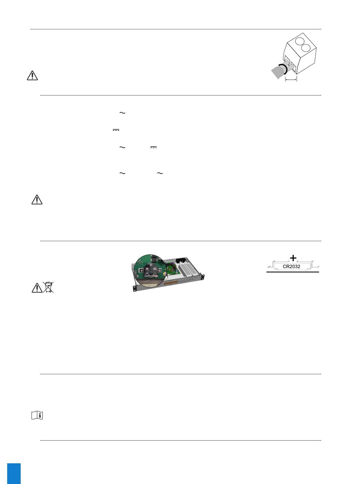
All cables must be securely attached to the chassis before being connected to the
various terminal blocks in order to prevent traction on connections. Conductors on the
same circuit must be attached to each other close to the terminal block to avoid reduced
isolation should one of the terminals become loose.
1 cm
Theequipment mustonlybeconnectedtothepowersupply
once it has been securely mounted in the 19” destination rack.
2.4.1. Power supply
Power supply management according to version:
> Netsilon 7 / 9 / 11 (100-240V ): mains power supply only.
> Connect the power cord to the AC IN connector at the rear of the device.
> Netsilon 7 / 9 / 11 (22-30V ): direct current only.
> Connect a DC cable and observe the polarity indicated at the rear of the device.
> Netsilon 7 / 9 / 11 (100-240V + 22-30V ): mains power supply and/or direct current power supply.
> Connect the power cord to the AC IN connector and/or a DC cable, being careful to observe the
correct polarity indicated at the rear of the device.
> Netsilon 7 / 9 / 11 (100-240V + 100-240V ): dual mains power supply.
> Connect the power cord(s) to the AC IN connector(s) at the rear of the device.
The functional earthing terminal can be attached to the cabinet frame (optional).
TheDCINpowersupplymustbeprotectedupstreambya6.3ATfuse.
When severalNetsilonunitsarepoweredfromthesamepowersupply,protecteachDCINinputwith
a separate 6.3 AT fuse.
Becarefultoobservethecorrectpolarityindicatedattherearofthedevice.
2.4.2. Backup battery - CR2032
If replacing the CR2032 battery, it is essential to observe the polarity, as indicated on the slot of the battery.
Caution :
> There is a risk of explosion if the battery is replaced by a non-compliant battery. Use only batteries
recommended by the manufacturer.
> Disposeofusedbatteriesinaccordancewiththeinstructionsgivenonourwebsite.
> Theaccumulatormustnotbeswallowed–riskofchemicalburns.
> Alwayskeepnewanddischargedaccumulatorsoutofthereachofchildren.
> Thisproductcontainsabuttonbatteryoraccumulator.Ifswallowed,thebuttonbatteryoraccumulator
cancausesevereinternalburnswhichmaybefatal.
> Ifyoususpectthatanaccumulatorcellmayhavebeeningestedorinsertedanywhereinthebody,you
must seek immediate medical attention.
2.4.3. Ethernet
The ETH0 Ethernet port, accessible on the rear panel of the device, enables easy connection to routers, switches
or hubs.
1) Use a shielded CAT.5E or CAT.6 cable Ethernet cable (RJ45)
2) Connect the Ethernet network cable to the RJ45 connector on the Netsilon rear panel.
TheproductiscommissionedbyactivatingtheON/OFFswitchontherearpanelofthedevice.
The Bodet company strongly recommends connecting and using Netsilon exclusively on a private
network(VLAN).
2.4.4. Alarm relay circuits
For the relay circuits, provide protection by means of a fused disconnect switch or circuit breaker of 1A maximum.
Maintenance must be performed with power off. Disconnect the power supply and relay circuits under hazardous
voltage.
11
3. COMMISSIONING
Netsilon configuration is performed exclusively on the web server. In order to be able to access the web server it is
necessary to configure the ETH0 port via the front panel keypad and the LCD screen.
TIP:inordernottodisruptNetsilonsynchronisationwiththeotherproductspresentonthenetwork,itis
importanttomaintainidentificationofthetimeserver.
There are two solutions for accessing the web server:
> With a DHCP server: automatic assignment of an IP address.
> Without a DHCP server: manual assignment of a xed IP address via the control panel in the Netsilon network
menu.
3.1 Factoryconguration
The default configuration parameters have been selected to facilitate initial configuration. A single account is
activated on shipment from the factory.
> Default web server user account:
> Username: bodetadmin
> Password: admin49
  Thisaccountcannotbedeleted.However,itisstronglyrecommendedtochangethepassword
When first running Netsilon, the default parameters are as follows:
Functions Default status Means of configuration
Control panel & LCD
screen
Unlocked Control panel (technician menu) + web server
Language: English Web Server
Rotation of information: time,
network, synchronisation and
system status
Web Server
USB port Enabled Web Server
ETH0 Ethernet port
Services :
HTTP : ON
HTTPS : ON
DNS : ON
Console: ON
SSH : ON
Web server
IP address not given Control panel + web server
12
3.2 Choosing the LCD screen display language
The network settings for configuration of the ETH0 port (assignment of an IP address) can be read or configured via
the Netsilon control panel. It is first necessary to select the product’s display language:
3.3 CongurationwithaDHCPserver
1) On start-up, the Netsilon time server waits for automatic assignment of an IP address by the DHCP server. This
may take a few minutes.
2) Once assigned, this IP address is shown on the LCD screen. By default, the LCD screen alternately displays
several parameters. To read the IP address on the LCD screen, consult the network menu using the Netsilon
control panel and LCD screen:
3) Enter the IP address, as seen on the LCD screen, into the web browser (Google Chrome®, Mozilla Firefox,
Microsoft Edge or Internet Explorer®).
4) See Chapter 4.Webservermenus.
192.168.1.0/24istheIPaddresswithCIDRnotation.
Exit the menu by pressing the button.
Language  ok
   õ
Language  ok
   õ
Language:ENGLISHú
   ok
Language:FRENCHú
   ok
Selection of languages available:
English, French, Italian, Dutch, German
and Spanish
10:54.32
Mon19SEP20__
S y s t e m    o k 
Network õ
Productinfo ok
Versionõ
Version  ok
Optioncardsõ
Optioncards ok
Language õ
10:54.32
Tues19SEP20__
S y s t e m    o k 
NetworkIPv4 õ
NetworkIPv4 ok
USBtransfer õ
DisplayETH0 ok
Config.ETH0 õ
192.168.1.0/24
Nogatewayok
13
3.4 CongurationwithoutaDHCPserver
Without automatic assignment of an IP address by a DHCP server, it is necessary to manually assign a fixed IP
address.
To manually configure the Netsilon network settings, enter the following three parameters:
> IP address assignment
> This is a unique address assigned to Netsilon by the network administrator. Ensure that the chosen
address is available.
> Subnet mask
> The subnet mask defines the number of bits taken by the IP address. The number of bits used in the
netmask may range from 8 to 30 bits.
> Gateway
> The gateway address is required if communication with Netsilon is outside the local network. By
default, the gateway is disabled.
To configure these three parameters, use the Netsilon network menu, via its control panel:
10:54.32
Tues19SEP20__
10:54.32
Tues19SEP20__
S y s t e m    o k 
NetworkIPv4õ
NetworkIPv4 ok
USBtransferõ
DisplayETH0 ok
Config.ETH0 õ
DHCP:YESú
IPaddressAutook
IPAddress:
192.168.1.0ok
IPmask:
255.255.255.000ok
IPgateway:
---.---.---.---ok
Savinginpro-
gress...
Resettinginpro-
gress...
DHCP:NOú
FixedIPaddressok
Config.ETH0 ok
õ
Enter the values with the and
keys.
Note:thesevaluesaredetermined
bythenetworkadministrator.
14
4. WEB SERVER MENUS
To access the Netsilon web server, follow these steps:
1) Note the Netsilon IP address.
2) Open a web browser page.
3) Enter the IP address into the browser’s address bar.
4) Enter the username and default password to access the web server. For info:
> Username: bodetadmin
> Password: admin49
> For more information, download full manual : SYSTEM > General > Online help
5. SSHCONFIGURATION-LIMITEDCONFIGURATION
> To access the SSH online command set interface, follow these steps (Netsilon must be connected to the network
via its ETH0 port)::
1) Download a program enabling you to log into Netsilon remotely (e.g.: PuTTY).
2) Note the IP address of Netsilon.
3) Open the program (PuTTY).
4) Enter the IP address.
5) Enter the default ID and password to access the command set. Remember:
> ID: bodetadmin
> Password: admin49
> For more information on the product and the list of online commands (via the ETH0 port): SYSTEM > General >
Online help
15
6. CONSOLECONFIGURATION-LIMITEDCONFIGURATION
> To access the Netsilon web server, follow these steps (Netsilon, via its COM serial port, must be connected to the
PC).
ThephysicalconnectionbetweenthePCandNetsilonmustbeadirectlinkviaanRS232(DB9)male/
female serial cable.
1) Download a program enabling you to log into Netsilon (e.g.: PuTTY).
2) Open the program (PuTTY).
3) Enter the communication port.
4) Click on “Serial” to check the parameters of the
ASCII RS-232 serial connection:
- 9600 baud, 1 start bit, 8 data bits, 1 stop bit, no
parity and No root login.
5) Enter the default ID and password to access the command set. Remember:
> ID: bodetadmin
> Password: admin49
> For more information on the product and the list of online commands (via the COM port): SYSTEM > General >
Online help
16
7. SUPPORT
> To request technical assistance for this equipment :
http://www.bodet-time.com/assistance-clientele.html
> Telephone support is available from Monday to Friday from 8 am to 12 pm and from 1:30 pm to 5 pm.
To speed up the diagnosis of your Netsilon, perform a system backup and note the Netsilon MAC address.
  • Page 1 1
  • Page 2 2
  • Page 3 3
  • Page 4 4
  • Page 5 5
  • Page 6 6
  • Page 7 7
  • Page 8 8
  • Page 9 9
  • Page 10 10
  • Page 11 11
  • Page 12 12
  • Page 13 13
  • Page 14 14
  • Page 15 15
  • Page 16 16

Bodet 907900 User guide

Category
Networking
Type
User guide

The Bodet 907900 is a versatile time server designed for precise timekeeping and synchronization in various applications. With its advanced features, it offers reliable timekeeping solutions for a wide range of industries and organizations. Here's a brief overview of its capabilities:

  • Accurate Timekeeping: The Bodet 907900 utilizes multiple time sources, including GPS, GLONASS, and an internal oscillator, to ensure highly accurate timekeeping.

  • Synchronization: It can synchronize time across a network of devices, ensuring that all connected clocks and systems display the same precise time.

Ask a question and I''ll find the answer in the document

Finding information in a document is now easier with AI