
User’s Manual
IP Telephony Gateway
Model No.: SP5008A, SP5018A, SP5058A
Website: http://www.micronet.info

1
About this User’s Manual
This User’s Manual gives users basic steps on installation and operation. Please
read this manual chapter by chapter.
Chapter 1. Introduction
Introduce the IP Telephony Gateway to users in terms of feature, appearance,
and application.
Chapter 2. Startup
Help user complete basic configuration.
Chapter 4. Web Administration
Provide command reference of Web Interface for advanced setting.
Chapter 3. Operation
Show user how to use the device to process phone call.
Chapter 6. Specification
List the specification of the gateway in detail.
Online Upgrade
Please refer to http://www.micronet.info/ for additional support.

2
Table of Content
1...Introduction.............................................................................................. 4
1.1 Key Features................................................................................................ 4
1.2 Physical Description..................................................................................... 5
2...Startup ...................................................................................................... 7
2.1 Login into the System................................................................................... 7
2.2 Network Configuration.................................................................................. 9
2.2.1 Static IP ..........................................................................................................11
2.2.2 DHCP............................................................................................................ 12
2.2.3 PPPoE........................................................................................................... 13
2.2.4 LAN Setting................................................................................................... 14
2.3 General configuration................................................................................. 16
2.3.1 PABX Mode (SP5018A only)......................................................................... 16
2.3.2 SIP Setting .................................................................................................... 18
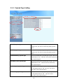
3...Web Administration............................................................................... 20
3.1 General configuration................................................................................. 20
3.1.1 SIP Advanced Setting.................................................................................... 20
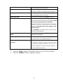
3.1.2 Payload Type Setting ....................................................................................22
3.1.3 Line Setting ................................................................................................... 24
3.1.4 Qos Setting.................................................................................................... 27
3.1.5 Speed Dial Setting......................................................................................... 28
3.1.6 Caller ID Setting............................................................................................ 30
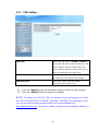
3.1.7 CDR Setting .................................................................................................. 32
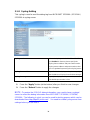
3.1.8 Syslog Setting ............................................................................................... 34
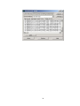
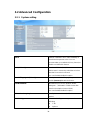
3.2 Advanced Configuration............................................................................. 36
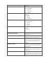
3.2.1 System setting............................................................................................... 36
3.2.2 SNTP Setting................................................................................................. 40
3.2.3 Codec Setting................................................................................................ 41
3.2.4 Voice Setting ................................................................................................. 42
3.2.5 Tone Setting .................................................................................................. 44
3.2.6 Phone Setting................................................................................................ 46
3.2.7 Digit Manipulation.......................................................................................... 48
3.2.8 Dial Plan........................................................................................................ 50
3.3 Management .............................................................................................. 52
3.3.1 Provision Server............................................................................................ 52
3.3.2 Save-Reload setting...................................................................................... 53
3.3.3 Upgrade Firmware......................................................................................... 54

3
3.3.4
Reset to Default............................................................................................. 58
3.3.5 Network Status.............................................................................................. 59
3.3.6 Version Info. ..................................................................................................60
3.3.7 Port Status..................................................................................................... 61
3.3.8 Password....................................................................................................... 62
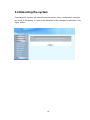
3.4 Rebooting the system................................................................................. 63
4...Operation................................................................................................ 64
4.1 Peer to Peer mode (FXO to FXS)............................................................... 64
4.2 Peer to Peer mode (FXS to FXS)............................................................... 68
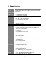
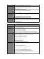
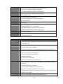
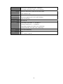
5...Specification........................................................................................... 72

4
1. Introduction
Micronet SP5008A / SP5018A / SP5058A are high-capacity SIP Gateway
Series that provides 8 FXS / 4 FXS + 4 FXO / 8 FXO ports, and suit to build an
IP-based communication platform with other VoIP devices. They meet enterprise’s
requirement for functionality (VoIP) upgrade and larger scale implementation by
interoperating with legacy PABX and IP PBX/Soft-switch.
To connect with legacy PABX, SP5018A supports PABX Mode for PSTN
backup. When network or power fails, PSTN lines (FXO) bypass to FXS ports and
users still can make/receive calls via PSTN lines.
In addition, SP5008A includes some wonderful PABX features for small
business. They help operate users on various VoIP applications, such as extension
calling among 8 FXS ports, inbound/outbound calls via SIP trunk, DID (direct line),
DOD, prefix routing, operator attendant, etc. Users can easily benefit from the
ease-to-use device.
1.1 Key Features
z IETF SIP standards compliant
z Support 1 RJ-45 WAN port and 4 RJ-45 LAN ports
z Support POTS interfaces: 8 FXS / 4 FXS + 4 FXO / 8 FXO ports
z Support single-account registration on FXS ports for representative number
z Support extension calling among FXS ports
z Support rich call features: call hold, call transfer, call forward, hotline, warm line,
speed dial, anonymous call, P2P call, etc
z Support PSTN prefix routing (SP5018A only)
z Support PABX mode for legacy PABX function upgrade (SP5018A only)
z Support PSTN lifeline – PSTN bypass in case of power or registration failure
(SP5018A only)
z Support detection of disconnect tone, polarity reversal, and loop current drop
(zero voltage) on FXO ports
z Well interoperability with industry-leading IP-PBX/Soft-Switch, such as Alcatel,
Lucent, Siemens, etc.

5
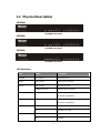
1.2 Physical Description
SP5008A:
SP5008A Front Panel
SP5058A
SP5058A Front Panel
SP5018A
SP5018A Front Panel
LED Indicators
LED Status Description
POWER On / Green The Power is on
READY Blink / Green Booting up for self test
Blink / Green Gateway reg. fails PROXY
Constant / Green Gateway reg. successes
WAN Blink / Green Transmitting or receiving data /Network
connection established
LAN(1-4) Blink / Green Transmitting or receiving data /Network
connection established
On / Orange Busy / Off-hook T(1*)
Off Available / On-hook
On / Orange Busy L(1*)
Off Available

6
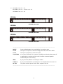
1*.
SP5008A: FXS = T1 - T8
SP5018A: FXS = T1 - T4, FXO = L1 - L4
SP5058A: FXO = L1 - L8
SP5008A
SP5008A Rear Panel
SP5058A
SP5058A Rear Panel
SP5018A
SP5018A Rear Panel
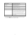
---------------------------------------------------------------------------------------------------
RESET Factory default button. Press and hold for 5 seconds to reset
T1-T8 The RJ-11 FXS port 1-8, connects analog phone sets, trunk line in PABX.
L1-L8
The RJ-11 FXO port 1-8, connect to PSTN
T1/P1-T4/P4 It is a pair of FXO and FXS connector. The different is that the when power off
or application is crashed, the FXO and FXS will be connected together
automatically for local surviving.
WAN RJ-45 port of 10/100M for connecting to modem
LAN(1-4) RJ-45 port of 10/100M for connecting to PC or hub/switch that connects PCs
DC 12V The power socket, input AC 100V~120V; output DC12V.3A
---------------------------------------------------------------------------------------------------

7
2. Startup
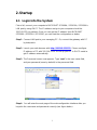
2.1 Login into the System
First of all, connect your computer to MICRONET SP5008A / SP5018A / SP5058A’s
LAN port by using DHCP. The IP address assign to your computer should be
192.168.123.x by default. Once you can get the IP address from MICRONET
SP5008A / SP5018A / SP5058A, you can start the configuration as below.
Step 1. Connect LAN port to your managing PC. Or, connect the gateway with PC
by hub/switch.
Step 2. Launch your web browser with http://192.168.123.123/. Please configure
IP address of PC with 192.168.123.x. Or set up your PC in DHCP mode to
get IP address automatically.
Step 3. The Password screen now appears. Type “root” in the user name field,
and your password (none by default) in the password field.
Step 4. You will enter the main page of the web configuration interface after you
keyed in the username and password correctly (see figure below).

8

9
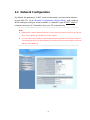
2.2 Network Configuration
By default, the gateway is in NAT mode (router mode) and can share Internet
access with PCs. Go to [ Network Configuration / WAN Setting ], and configure
WAN setting according to actual condition. In default IP type of DHCP client, it
requests necessary IP information from your ISP automatically.
-----------------------------------------------------------------------------------------------------
Note:
1. Different ISPs require different methods of connecting to the Internet. Please consult your
ISP to select right IP type (Fixed IP, PPPoE) of WAN.
2. You can retrieve the IP address of the WAN port by keying #126# on the phone set that is
connected to the FXS port of the gateway. You will hear an IVR announcing the current IP
address of the WAN port.
-----------------------------------------------------------------------------------------------------

10
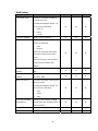
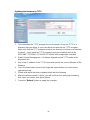
WAN Setting
Item Description Static IP DHCP PPPoE
Connected mode Select the connection method for
the WAN port of the
SP5008A/SP5018A/SP5058A, you
can choose the following:
z Static IP
z DHCP
z PPPoE
V V V
Current IP Address Show current IP address
V V V
DNS server mode Select the DNS behavior, you can
choose the following:
z Auto
z Manual
“DNS auto” will retrieve the DNS
information sent from the DHCP
server.
“Manual” will look at the specified
Primary and Secondary DNS
address.
V V V
Primary DNS
address
Specify the address of the Primary
DNS.
V V V
Secondary DNS
address
Specify the address of the
Secondary DNS.
V V V
WAN Link Speed Select the connection speed for the
WAN port of the
SP5008A/SP5018A/SP5058A, you
can choose the following:
z Auto
z 100M
z 10M
V V V
HTTP port for WEB
management
Specify the port number for WEB
management, the allowable range is
80,1024~65535.
V V V
IP address Specify the IP address.
V
Subnet mask Specify the subnet mask.
V

11
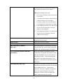
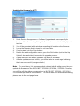
Item Description Static IP DHCP PPPoE
Default gateway Specify the IP address of the default
gateway.
V
Remote access
restriction
Restricts/Blocks users connecting to
the WAN port’s IP remotely, you can
Enable/Disable this option.
V V V
PPPoE userID Specify the username of the PPPoE
account
V
PPPoE password Specify the password associated to
the PPPoE account above.
V
Reboot after remote
host disconnection
When the remote host (PPPoE)
fails, the gateway will retry 3 times
to reconnect, if there is no reply
from the remote host within 3 tries,
then the gateway will reboot. You
can Enable/Disable this option.
V
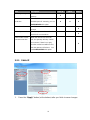
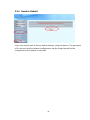
2.2.1 Static IP
1. Press the “Apply” button (at the bottom) after you finish to save changes.

12
2. Press the “Reboot” button to apply the changes.
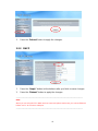
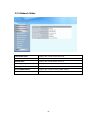
2.2.2 DHCP
1. Press the “Apply” button (at the bottom) after you finish to save changes.
2. Press the “Reboot” button to apply the changes.
-----------------------------------------------------------------------------------------------------
Note:
When you are using DHCP in WAN and not connected, please make sure you connect Ethernet
before use PC to connect to LAN port.
-----------------------------------------------------------------------------------------------------

13
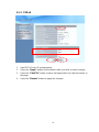
2.2.3 PPPoE
1. Input PPPoE user ID and password
2. Press the “Apply” button (at the bottom) after you finish to save changes.
3. Press the “CANCEL” button (next to the Apply button) to clear the values in
the page.
4. Press the “Reboot” button to apply the changes.

14
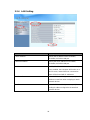
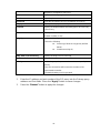
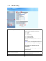
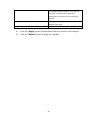
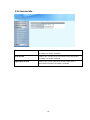
2.2.4 LAN Setting
ITEM Description
LAN IP address Specify the IP address of the SP5008A /
SP5018A / SP5058A LAN port.
LAN mask address Specify the mask address for SP5008A /
SP5018A / SP5058A LAN port.
DHCP server
Enable/Disable DHCP function on the LAN port.
Once enabled, the LAN ports will function as a
DHCP server, network devices connected to
them will be issued with IP addresses.
IP address from When DHCP is enabled, you can specify the IP
address to start from when assigning to attach
network devices.
IP address to When DHCP is enabled, you can specify the
ending IP address assigned to the attached
network devices.

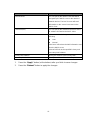
15
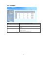
ITEM Description
Domain Name You can specify the domain name that will be
assigned by the DHCP server to the attached
network devices. The DHCP server will send
information on the “server host name” to the
DHCP client.
Lease time(sec) You can specify the maximum lease time of the
IP address allocated to the DHCP client.
DNS server mode Select the DNS behavior, you can choose the
following:
z Auto
z Manual
“DNS auto” will retrieve the DNS information sent
from the DHCP server.
“Manual” will look at the specified Primary and
Secondary DNS address.
Primary DNS address Specify the address of the Primary DNS.
Secondary DNS address Specify the address of the Secondary DNS.
1. Press the “Apply” button (at the bottom) after you finish to save changes.
2. Press the “Reboot” button to apply the changes.

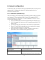
16
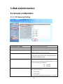
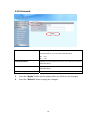
2.3 General configuration
To make VoIP calls, you will need a SIP account provided by the SIP Proxy you are
registered with. To configure the relevant SIP settings, please refer to the
instructions explained below.
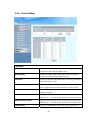
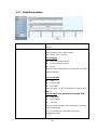
2.3.1 PABX Mode (SP5018A only)
This quick setting is used for MICRONET SP5018A to operate in PABX connection
mode between PSTN and traditional PABX. Enable PABX mode for ISP/ITSP
scenario that forbids SIP call to/from PSTN via the gateway (SP5018A). The call
scenario will be working as below:
1. For FXO incoming call, it will route to corresponding FXS directly (1 by 1)
2. For FXS outgoing call, it will route to VOIP except those prefix set in FXO
dialing Prefix.
3. For VOIP incoming call, it will route to FXS based on the called number
4. When VOIP call is failed to be called out such as register fail or network
issue, the call will be route to FXO as backup.
5. When MICRONET SP5008A / SP5018A / SP5058A is malfunction or
power failure, the all call will be directly bypassed to FXO.
PABX Connection
To enable PABX behavior or not.
SIP Setting
Please refer to 3.3.2.1
Representative Number Only
It is used (Yes) when you only have 1 SIP account and
would like to be shared for all FXS lines. Please refer to

17
3.3.2.1
Primary FXS SIP settings
When you have multiple SIP accounts for each FXS line,
please set Representative Number Only to No. Then refer
to 3.3.2.1 for the detail
FXO Dialing Prefix
When the prefix is set here, the call will be route to FXO
instead of VOIP.

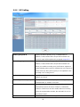
18
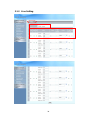
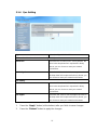
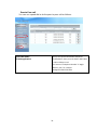
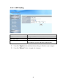
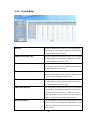
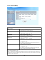
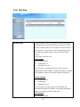
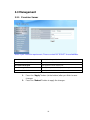
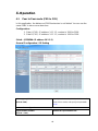
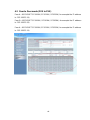
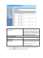
2.3.2 SIP Setting
Primary proxy/P2P IP
Specify the data of primary proxy : Enable/Disable, IP
address, Port#, Domain Name, Expire time and MWI TTL.
The P2P mode will be explained in paragraph Appendix A
Secondary proxy
Specify the data of secondary proxy: Enable/Disable, IP
address, Port#, Domain Name, Expire time and MWI TTL.
When you enable secondary proxy, it will start to register no
matter whether primary proxy is registered or not. However, it
will be used only when primary proxy is not registered or the
incoming call is coming from it.
Outbound proxy
Specify the data of Outbound proxy: Enable/Disable, IP
address and Port#.
Secondary Outbound proxy
Specify the data of Outbound proxy for secondary proxy:
Enable/Disable, IP address and Port#.
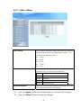
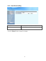
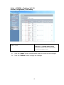
Representative Number
The representative number is working as a SIP trunk for the
selected FXS line (for all FXS or FXO/FXS combination
model) or FXO line (for all FXO model). When an incoming
call to the representative number, the selected FXS or FXO
port will be hunted.
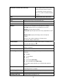
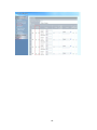
Enable
Enable the Line, the default setting is “Enable” and it will

19
Register or Unregister to SIP Proxy
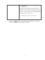
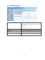
Account
Input the SIP Proxy registration account ID.
Number
Input the phone number.
Password
Input the password of IP Proxy registration account ID.
Display name
Specify the Display name of the phone number
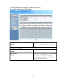
Forward
Specify the Representative forwarding type to be used, only
choose busy
Forward Number
Specify the number to be forwarded when the specified
forward condition is met.
Ring Type
Select the Ring Type of representative number. You can
choose the following:
z Serial ring (Follow the ring priority defined
below)
z Simultaneous(ring all)
Ring Time (s) for Serial ring
Specify the Ring Time for Serial ring
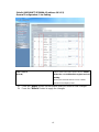
Status
Displays the registration status, whether it is registered or not.
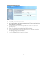
Priority
Select the group of representative number, and specify the
priority.
Only the checked line will become the member of the
representative number.
The default setting L1~L8 is grouped.
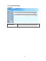
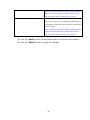
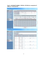
1. Enter the IP address and port number of the SIP proxy into the Primary proxy
address and Port fields. Press the “Apply” button to save changes.
2. Press the “Reboot” button to apply the changes.
Page is loading ...
Page is loading ...
Page is loading ...
Page is loading ...
Page is loading ...
Page is loading ...
Page is loading ...
Page is loading ...
Page is loading ...
Page is loading ...
Page is loading ...
Page is loading ...
Page is loading ...
Page is loading ...
Page is loading ...
Page is loading ...
Page is loading ...
Page is loading ...
Page is loading ...
Page is loading ...
Page is loading ...
Page is loading ...
Page is loading ...
Page is loading ...
Page is loading ...
Page is loading ...
Page is loading ...
Page is loading ...
Page is loading ...
Page is loading ...
Page is loading ...
Page is loading ...
Page is loading ...
Page is loading ...
Page is loading ...
Page is loading ...
Page is loading ...
Page is loading ...
Page is loading ...
Page is loading ...
Page is loading ...
Page is loading ...
Page is loading ...
Page is loading ...
Page is loading ...
Page is loading ...
Page is loading ...
Page is loading ...
Page is loading ...
Page is loading ...
Page is loading ...
Page is loading ...
Page is loading ...
Page is loading ...
Page is loading ...
Page is loading ...
-
 1
1
-
 2
2
-
 3
3
-
 4
4
-
 5
5
-
 6
6
-
 7
7
-
 8
8
-
 9
9
-
 10
10
-
 11
11
-
 12
12
-
 13
13
-
 14
14
-
 15
15
-
 16
16
-
 17
17
-
 18
18
-
 19
19
-
 20
20
-
 21
21
-
 22
22
-
 23
23
-
 24
24
-
 25
25
-
 26
26
-
 27
27
-
 28
28
-
 29
29
-
 30
30
-
 31
31
-
 32
32
-
 33
33
-
 34
34
-
 35
35
-
 36
36
-
 37
37
-
 38
38
-
 39
39
-
 40
40
-
 41
41
-
 42
42
-
 43
43
-
 44
44
-
 45
45
-
 46
46
-
 47
47
-
 48
48
-
 49
49
-
 50
50
-
 51
51
-
 52
52
-
 53
53
-
 54
54
-
 55
55
-
 56
56
-
 57
57
-
 58
58
-
 59
59
-
 60
60
-
 61
61
-
 62
62
-
 63
63
-
 64
64
-
 65
65
-
 66
66
-
 67
67
-
 68
68
-
 69
69
-
 70
70
-
 71
71
-
 72
72
-
 73
73
-
 74
74
-
 75
75
-
 76
76


Ask a question and I''ll find the answer in the document
Finding information in a document is now easier with AI
Other documents
-
MicroNet SP5008A Quick Installation Guide
-
-
MicroNet SP5008A User manual
-
MicroNet SP5220 User manual
-
 Zycoo G Series FXO VoIP Gateway Owner's manual
-
Microsoft SP5100/S User manual
-
LevelOne VOI-8003 User manual
-
WELLTECH WILLGATE26 Series User manual
-
 DBL Technology VoIP FXS+PSTN Gateway User manual
-

