
INSTRUCTION MANUAL ASI-16
All Sky Imager
Cloud Base Height Software

Table of Contents
1 User Information ............................................................................................................................. 1
1.1 Warranty .............................................................................................................................. 1
1.2 Contact Information ............................................................................................................. 1
2 Cloud Base Height Software .......................................................................................................... 2
2.1 System Requirements ......................................................................................................... 3
2.1.1Hardware Requirements 3
2.2 Software Installation ............................................................................................................ 6
2.2.1Install schemes 6
2.2.2General functions 7
2.3 Main Window of Cloud Base Height Software ..................................................................... 8
2.4 Overview of menu items ...................................................................................................... 9
2.4.1Show Curves - Display of Cloud Base Height 10
2.4.2Show Evaluation 11
2.4.3Configuration Of Pairs 13
2.4.4Configuration Evaluation 14
2.4.5Convert Degrees to Dezimal 14
3 Appendix ...................................................................................................................................... 15
3.1 References .............................................................................................................. 15

Cloud&Base&Height&Manual&&&1&
1 User Information
Thank you for purchasing the Cloud Base Height Software. Make sure to read this instruction
manual thoroughly and to understand the contents before starting to operate the instrument. Keep
this manual at safe and handy place for whenever it is needed.
For any questions, please contact us at the CMS office given below.
CMS reserve the right to make changes to specifications without prior notice.
1.1 Warranty
For warranty terms and conditions, contact CMS or your distributor for further details.
CMS guarantees that the product delivered to customer has been verified, checked and
tested to ensure that the product meets the appropriate specifications. The product warranty
is valid only if the product has been installed and used according to the directives provided
in this instruction manual.
CMS shall in no event be liable for incidental or consequential damages arising from the
faulty and incorrect use of the product.
In case of any manufacturing defect, the product will be repaired or replaced under warranty.
However, the warranty does not apply if:
• Any modification or repair was done by any person or organization other than CMS
service personnel.
• The damage or defect is caused by not respecting the instructions of use as given
on the product brochure or the instruction manual.
1.2 Contact Information
EKO Europe, Middle East, Africa,South America
Lulofsstraat 55, Unit 32
2521 Al, Den Haag
The Netherlands
P. + 3 1 ( 0 ) 70 3 05 0 11 7
F. + 3 1 ( 0) 70 3 84 0 6 0 7
info@eko-eu.com
www.eko-eu.com

Cloud&Base&Height&Manual&&&2&
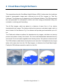
2 Cloud Base Height Software
Version 1.0. First printed November 2015, this revision March 2016
This manual describes the Cloud Base Height Software (CBH). It determines the cloud base
height of stereographic image pairs, delivered by two All Sky Imagers (or Total Sky
Cameras). The images are pre analysed by the Findclouds Software. The CBH represents
the next generation for atmospheric science and solar energy professionals doing site
evaluation, monitoring and forecasting.
Two All Sky Imagers, which are placed in a distance of about 1km to 3 km, deliver
hemispherical sky images. The distance defines the maximum evaluation height, which is
about a factor 6 of the distance. E.g. 2 km distance will provide good evaluations up to ≈12
km.
The Findclouds software equalizes the hemispherical sky images, calculates an intensity
picture and creates a binary cloud mask. The cloud mask differentiates between blue sky
and clouds. The cloud mask is applied to the intensity picture. This picture is stored on disk.
The CBH software reads these stored pictures and uses the 2 hemispherical sky images
taken at the same time from the 2 All Sky Imagers, to determine the Cloud Base Height.
Finally the CBH software saves the results to a text file.

Cloud&Base&Height&Manual&&&3&
2.1 System Requirements
2.1.1 Hardware Requirements
The software uses less than 10 MB hard disk space.
2.1.1.1 Operating-System-Requirements
MS-Windows-Version: Windows 2000, Windows XP, Windows Vista, Win7, Win8.
Linux-Version tested for current distributions of CentOS, Fedora, Debian, Ubuntu. Using
other distributions, it might be necessary, to install missing libraries, or to start software using
distributed libraries. There is no source code delivered, just the binary files.
Also there is no Linux installation software, only a Linux directory on install CD, including
required Linux files and a "readme" file.
2.1.1.2 General Requirements
For view of PDF manual there must be a pdf-viewer installed and the file extension ".pdf"
should be assigned to this viewer.

Cloud&Base&Height&Manual&&&4&
2.1.1.3 Program Files
"Program files" are permanent files, that won't be
changed after installation, except of an update.
So these files can be installed by the
administrator in a protected read only directory ,
to be safe against viruses and other kinds of
vandalism.
The recommended name of the installation directory is "cloudheight" and inside of this
directory there is a subdirectory "prg" for program core files. This is a standard structure for
CMS software and often beside from "prg" there are other directories
Program core files are
• clouddir.sys - link file to the associated data directory, it contains simply the path
• cloudheight.exe - the executable software
• Manual_Cloudcam.pdf - the common manual of CMS "cloud" software
That's all, the software doesn't need additional dll-files and doesn't use the registry, all
installation is done inside of "cloudheight" directory and no windows system is affected.

Cloud&Base&Height&Manual&&&5&
2.1.1.4 Data Files
The program utilizes the images of the
Total Sky Camera and prepared by the
CMS Findclouds software.
The format of filenames is defined
"YYYYMMDDHHMMSS_ext.jpg".
"YYYYMMDD" means date of photo
(Year, Month, Day) and "HHMMSS"
means time of photo (Hour, Minute,
Second) specified in UTC time. "ext" is
additional information about image type.
There are three types of images the
CloudBaseHight software can evaluate,
"brbg_intens", "thick_intens" and
"thin_intens". These images must be
exported by Findclouds software and
they must be ".png" images
The software works with a predefined
directory structure:
The screenshot on right side shows a typical Cloudcam data directory. It contains directories
for the Cloudcams, like "ccam_01002, ccam_01321..." and the directory "system" for
Cloudcam Control configuration, which now is also in use for Cloudheight configuration
"cloudheight.cfg".
Every Cloudcam directory contains directories for the days and again a "system" directory,
more details can be found in the Cloudcam manual.
Inside of the "days" directories the Findclouds software creates an additional directory
"evaluations" for the processed images and the text file of evaluated cloud heights.
2.1.1.5 Evaluation files
The evaluation files are named by the Cloudcam pair, the date and the type of evaluation
source, e.g. "cloudheight_01183_01322_20150911_brbg.txt".

Cloud&Base&Height&Manual&&&6&
01183 … first ASI
01322 … second ASI
20150911 … date
brbg … type of evaluation; may be also ”tick” or “thin”
txt … file extension
The evaluation results will always be saved to the evaluation folder of the first Cloudcam.
Because one Cloudcam can be paired with several other Cloudcams, it is possible, that
there are files of more than one pair inside of the directory. Also it is possible, that there is
no text file, because the Cloudcam of the directory is the second one for all pairs.
There are three types of cloudheight evaluations: "brbg", "thick" and "thin". They will be
written to different files. For most cases the "brbg" evaluation probably is sufficient.
The path to the root data directory "cloudcam" is defined by file "clouddir.sys" inside of the
Cloudheight program directory "cloudheight/prg".
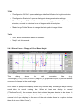
Example:
% FirstASI SecondASI Date Type
% 01183 01322 20150911 brbg
% Time Cloudiness Quality H0 H1
085000 0.05 5 4140 7230
090000 0.17 5 4120 4680
091000 0.13 9 3530
092000 0.43 9 3630
093000 0.58 9 3420
094000 0.43 9 3450
095000 0.21 9 3400
100000 0.02 0 -2
101000 0.01 0 -2
102000 0.00 0 -2
103000 0.00 0 -2
% <end>
The tag <end> shows that evaluation file is not cut off, but there is a regular end of
evaluation. When checking for this tag the file can be read in, without causing an
end of file error.

Cloud&Base&Height&Manual&&&7&
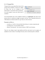
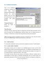
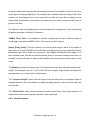
2.2 Software Installation
This is the installation
software for installing the
Cloud Base Height
Software to MS-Windows.
Normally this window
appears, when you insert
the install medium to your
computer and press
[Install].
"Program Directory"
shows the target of
installation.
"Data Directory"
shows the directory, that will be used for configuration files and where evaluations will be
saved. Be aware that CloudBaseHeight software should use the existing directory of
Cloudcam / Findclouds to evaluate new images delivered from those programs.
"Info" list shows progress of installation and when it is finished, you can close this window
and start CloudBaseHeight software by desktop link or start menu.
2.2.1 Install schemes
For customized installations, there are three basic installations schemes "Install Scheme":
2.2.1.1 Install scheme standard
The program directory will be created in the standard program directory and the data
directory will be created in the standard data directory. It is possible to choose between user
specific installation and common installation, which provides the software for all users. You
can choose this also on right-hand side by "User scope".
The program directory and the data directory are placed in different locations and the
administration of access rights is considered automatically. The user doesn't need to be
administrator, because all of the files and directories, that will be changed or created new,

Cloud&Base&Height&Manual&&&8&
are in scope of users access rights.
2.2.1.2 Install scheme all in one
The program directory and the data directories will be in a common installation directory
"Cloudheight". This is the most easy way to handle software and data e.g. for backups, but
it is necessary to set user privileges for access of data directory or login as administrator. It
is possible to choose another target directory than suggested, but the final installation
directory is hard coded for "Cloudheight". So it's a choice of basic directory, e.g. "c:\" for
installation of "c:\Cloudheight" or "d:\CMS" for installation of "d:\CMS\Cloudheight".
2.2.1.3 Install scheme custom
The program directory and the data directory can be chosen before installation. The user
must be administrator or access rights for users must be set by the administrator.
2.2.1.4 Links
Before installation it is possible to configure the links to be created:
• Default is to use the Startmenu to create a new entry [Start] -> [Programme] ->
[Cloudheight] which contains links to the software and documentation.
• Also there is a Desktop link default, for quick start of software by double click on
Desktop icon.
• The Autostart link can be activated to start the software automatically when the
operation system starts.

Cloud&Base&Height&Manual&&&9&
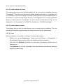
The install software will
appear like this, when
there was an existing
version of the software
found. By using the
buttons it is possible to
[Update] the existing
software, or to uninstall it.
Also it is possible to set the
Install Scheme from
"Uninstall" to an
installation scheme for
installing the new version
besides the existing version. But this is not recommended, because it can cause problems
regarding to double links and uninstall information.
2.2.2 General functions
[Install] starts the installation to the shown target directories.
[Uninstall] uninstalls the software.
[Update/Repair] overwrites the existing installation by the current version.
[Close] terminates the installation software without processing anything else.

Cloud&Base&Height&Manual&&&10&
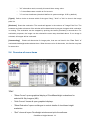
2.3 Main Window of Cloud Base Height Software
Through the main window it possible to select the images for evaluation. It shows the results of
evaluation, the original images and the "intense-mask" of the images.
"Cloudcam Pairs": Is used to select pairs of All Sky Imagers (ASI). It is possible to choose more
than one pair. The software automatically loads the date directories of the ASI's to the list of "Date
Pairs".
"Date Pairs": Are the dates which are common for both ASI's. Only common date pairs will be
shown.
Inside of the "Date Pairs" browser it is possible to select one or more days. The software will read
these selected directories and insert all common intensity pictures to the browser "Image Pairs".
You may select one DatePair by clicking on its entry, more DatePairs by holding the "Ctrl" key. It is
possible to add a block of DatePairs by clicking to the first entry, holding the "Shift" key and clicking
to the last entry.
"Image Pairs": The "Image Pairs" list shows all intensity pictures found in selected "Date Pairs" .
The file names of the intensity images are splitted into time and original type of cloud evaluation.
Only valid pairs of images with the same time are shown.
Column 1: "Image" shows the time
Column 2: "Type" shows the type of cloud evaluations ("brbg", "thick" or "thin").
Column 3: "Cloudiness" shows the cloudiness, calculated from the intensity image.
Column 4: "Quality" shows the quality of the height result:
• "0" clear result.
• "3" more results by match value are possible, best was chosen.
• "4" two results are possible, best was chosen by slope
• "5" two results are possible, best was chosen by match value
• "9" no result.
Column 5, 6: "H0" & "H1" show the heights in [m] above sea level, or the values "-1" or "-2":
• "H0" result of best match.

Cloud&Base&Height&Manual&&&11&
• "H1" alternative result, normally this would be a wrong value.
• "-1" the software was not able to find a result.
• "-2" too less cloudiness (threshold defined in system settings: 0.05 by default).
[Types]: Calls a choice to choose which of the types "brbg", "thick" or "thin" to show in the image
pairs list.
[Evaluate]: Starts the evaluation. The results will appear in the columns of "Image Pairs" list. The
browsers and other elements of the window will be deactivated to prevent changes while evaluation
is running. The evaluation can be stopped by pushing the button [Evaluate] a second time. For
evaluation purposes, the image can be selected the same way described above. If non image is
selected, all images will be evaluated.
[Outstanding]: Checks all directories for image pairs, that are not listed in the "Date Pairs" of
evaluated cloudheight and evaluates them. When there are a lot of directories, this function may last
for some time.
2.4 Overview of menu items
"File"
• "Show Curves" opens graphical display of CloudBaseHeight evaluations for
selected All Sky Imagers (ASI).
• "Hide Curves" closes all open graphical displays.
• "Show Evaluation" opens a dialogue to control details of cloud base height
evaluation.
• "Quit" closes all open Cloudheight windows and quits the software.

Cloud&Base&Height&Manual&&&12&
"Edit"
• "Configuration Of Pairs" opens a dialogue to define ASI pairs for height evaluation.
• "Configuration Evaluation" opens a dialogue to change evaluation settings.
• "Convert Degrees To Decimal" opens a tool to change geolocations from degrees,
minutes, seconds to a decimal value of degrees with decimal place.
• "Basic Image Folder" allows to change the basic path to image folders.
"Info"
• "Info" shows informations about the software.
• "Help" calls this manual.
2.4.1 Show Curves - Display of Cloud Base Height
This dialog shows the daily evaluation files (e.g.
"cloudheight_01183_01322_20150911_brbg.txt”) as graphical line plot, to provide a better
overview of changes in the cloud height.
As a matter of principle the display shows only selected days. Showing all days normally
would take too much drawing time. When at least one display is opened
("File/ShowCurves"), the software knows that selected days are desired to be shown. It
opens more displays, when days of another CloudcamPair is selected. Because this can
cause a lot of open displays, in the menu of the main window there is an option to close
them all at once ("Hide Curves").

Cloud&Base&Height&Manual&&&13&
As shown above each day gets an own drawing area and it is possible to scroll to the left or
to the right for viewing single days. The example above doesn't show the original size of the
window, but an enlargement to show more than one day at a time. Every display can be
resized and positioned to match better to screen area and chosen range and will store its
position and size.
On right-hand side of the display there are some options for configuration. They are affecting
all display windows of different Cloudcams.
"BRBG, Thick, Thin": It is possible to activate or deactivate the plot of different types of
cloud height evaluations (BRBG, Thick, Thin) and to set their colours.
[Start], [End], [Auto]: This input allows to set the the time range to show. It is possible to
enter times in format "HH:MM" and to take them over by [enter] key or by pushing the button
beside the input. When there is no time given, the software will take the time range out of
the evaluation data, this can be forced by button [Auto] to overwrite existing times. Also it is
possible to enter just begin or end and the software will calculate the missing value of time
range.
The [Ratio] input sets the aspect ratio of the drawing area the way, that width will be ratio *
height. The example value of "1.414" is the DIN ratio of paper, larger values will stretch the
drawing area, e.g. to show lots of values better.
The "Common Height" option sets the height of the left side scale to the largest height of
all graph windows. So it is possible to compare the graphs directly, without need to take care
for the scale.
The "Show Select" option shows a black line at the actual time of the current selection. It
makes the plot follow an ongoing evaluation, when activated.
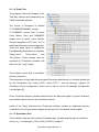
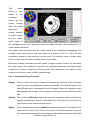
2.4.2 Show Evaluation

Cloud&Base&Height&Manual&&&14&
This dialog
allows to view
details of the
evaluation. It
shows the two
source images
(left), the height
dependent
overlap (middle)
of these images
and the match
graph (right) of
the overlapping area. It can be used to check the basic settings of the camera pair or to
control failed evaluations.
The graph on the right side shows the match values of the evaluations (overlapping). The
example shows the minimum with best match at a height of 2377 m. There are also
evaluations, where no clear minimum can be found. The absolute value of match value
doesn't matter, only the relative minima tell about the match.
Before the software evaluates the match graph, it applies a spline function for smoothing
the match values. This makes the evaluation more reliable, because this provides a better
recognition of minima, slopes and inflexion points. The parameters of the spline can be
changed in the menue items of Edit/SystemSettings.
2.4.2.1 Automatic fitting of overlap:
[Swap] The two colourised source images are arranged by the order of the Cloudcam
pairs. A wrong order makes the evaluation impossible. To check this, there is the
button [Swap] which exchanges the source images. When the evaluation works
after swapping the images, it is necessary to exchange the order of the Cloudcam
pair.
[Show]: The check box [Show] belongs to the automatic evaluation. When activated, the
ongoing overlapping is shown in the middle field. This looks nice, but there is no
real benefit and the evaluation lasts longer.
[Mark]: When activated, the check box [Mark] shows all points used for calculation of the
match value in white colour. This is very useful for manual evaluation, because
this accentuates the image structures and provides a better estimation of the best

Cloud&Base&Height&Manual&&&15&
match. Without "mark" the overlapping area will just get "more black" when there
is a good match and this is not plain to see.
[Reset]: The button [Reset] resets the overlap area to the starting height.
[Evaluate]: The button [Evaluate] allows the automatic evaluation of Cloud Base Height.
The example above is the result of this evaluation.
2.4.2.2 Manual fitting of overlap:
The main area in the middle shows the overlapping of the original, not colourised source
images, It can be controlled by the rollers "Direction" and "Height".
"Height": When the roller "Height" is in use, it is possible to overlap the images manually,
until there are matching structures. The example above shows on both source
images a hole with red border. The images in the middle are overlapped in a
way, that the holes lie on top of each other. The cloud base height, adjusted by
the roller, is shown in the output field named "Height [m]" and the corresponding
match value is shown in the output field named "Matchvalue".
"Direction": When the structures didn't match by angle, it is possible to overlap the images
by adjusting the roller "Direction". When there is a better match after that, the
direction must be changed at the Cloudcam pair configuration. The direction,
adjusted by the roller, is shown in the output field "Angle [°]". The output field
"Distance" shows the specified distance between the two All Sky Imagers and
completes the basic adjustments of the camera pair.
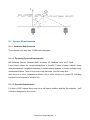
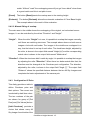
2.4.3 Configuration Of Pairs
This dialog provides a table to
define Cloudcam pairs and
their options. The current row
is selected by dark blue colour.
The two numbers of the pair
are shown for group of [Del
Row] and [Get Values] button.
[Add Cloudcam] provides a
choice that shows every All
Sky Imager found inside of the

Cloud&Base&Height&Manual&&&16&
basic image folder. As soon an All Sky Imager is selected, it appears as header of a new
line inside of the table. Now it is possible to select the second All Sky Imager by clicking to
the second column. This will open a choice, where the second Cloudcam can be selected.
Please be aware, that the valid sequence of
Cloudcam pairs depends on the location.
The pairs must be arranged the way, that
the first Cloudcam is on west side and the
second Cloudcam is on east side of the
sequence. So the second Cloudcam must
be in a direction of -90° to +90° east from the first one.
Now the distance in [m] between the Cloudcams (Dist [m]), the direction in [°] to the second
Cloudcam (Dir [°], in floating point numbers) and the elevation above sea level in [m] of the
Cloudcams (Alt1 [m], Alt2 [m]) have to be be entered. This may be done manually or on
automatic mode. For automatic imput use the button [Get Values]. For manually input use
the keyboard. The <Tab> key jumps to the next cell on the right, the <Enter> key jumps to
the next cell below.
[Get Values] When there are valid values inside of Cloudcam configuration (Longitude,
Latitude and Altitude), the software can use these values to determine the values of distance
and direction. The button [Get Values] inserts the values to the selected row.
[Del Row] removes the selected row from the table.
[Del Invalid] deletes lines with a cloudcam that can't be found in the basic image directory.
[Add Custom] allows to choose an arbitrary directory as basic directory of one Cloudcam.
This directory will be shown as custom directory with a negative index value. But beside of
that it will be usable the same way as a standard Cloudcam directory. The only difference is
that the software doesn't create an additional system directory, but writes the configuration
file directly to the custom directory.
[Del Custom] allows to delete a previously defined custom directory. This will also delete
all Cloudcam pairs, that use this directory.
[Ok] takes over the changes, saves the configuration to disk and closes the window.
[Cancel] closes the window and discards changes.

Cloud&Base&Height&Manual&&&17&
2.4.4 Configuration Evaluation
This dialogue provides basic settings of the system.
Ranges and recommendations of the settings are provided
by tooltips and will be shown, when placing mouse arrow
over the input field.
Mirror Images When Loading: The sky images are
directed from ground to clouds (upwards). For evaluation
they are "ground based", that means the images are seen
as projected to the ground (downwards). To achieve this,
the original image must be mirrored. Normally this check box is deactivated, because the Findclouds
software already mirrored the images.
Automatic Evaluation Of New Files: When this check box is activated, the software checks all
evaluation directories of the current date for new images and evaluates them automatically, when a
pair is complete.
Automatic Evaluation Days Back: This makes it possible to enlarge the range of dates of the
automatic evaluation. When there is a ''1'', the software checks the files of today and yesterday.
When there is a ''2'', it spans two days back and so on.
Factor For Height From Distance: The range of cloud heights, that can be evaluated, depends on
the distance between the cameras. For rising heights, the step size increases and the result
becomes inaccurate. This factor adjusts the desired accuracy for the range of heights, the current
Cloudcam pairs provide. Recommended values are from range 5 to 7, but the user might find other
values useful.
Minimal Cloudiness For Evaluations: This entry allows to set the threshold of minimum
cloudiness to evaluate the Cloud Base Height. The default value is 0.05 (cloudiness of 5%). The
value of 0.00 activates evaluation for all images. The maximum value of 1.0 corresponds to a totally
clouded sky.
The CloudBaseHeight software retrieves the cloudiness of the image from the masked parts of the
source images. When there are no or just a few clouds, it is critical to evaluate a cloud height,
because often there are no clouds matching together.
Spline Degree: To ac hie ve a bet ter ev al ua tio n, the match values are smoothed by a spline function.
The degree of the spline function controls, how close the spline will cover the original graph. A high
number will cause the spline to cover the original graph better (longer calculation time is required),
a low number makes the spline more smooth. The valid range goes from 10 to 500, but should be
near the default of 100. It is also possible to deactivate this function completely by inserting a “0”.

Cloud&Base&Height&Manual&&&18&
Spline Damp: The spline damp controls the damp of the spline function. Valid numbers are “-5” to
“5”, the default is 1.
Number Of Steps: This is the number of overlap operations, the automatic evaluation will execute
to determine the cloud height. A low number results in a fast, but inaccurate evaluation, a high
number will be slower, but more accurate. So the user can adjust the evaluation to the best
compromise between speed and accuracy. The default value of 50 provides a fast evaluation.
2.4.5 Convert Degrees to Dezimal
Opens a tool to change geolocations from degrees, minutes, seconds to a
decimal value of degrees with decimal place. The result can be cut&paste
from "Dezimal Location" output.
Page is loading ...
Page is loading ...
-
 1
1
-
 2
2
-
 3
3
-
 4
4
-
 5
5
-
 6
6
-
 7
7
-
 8
8
-
 9
9
-
 10
10
-
 11
11
-
 12
12
-
 13
13
-
 14
14
-
 15
15
-
 16
16
-
 17
17
-
 18
18
-
 19
19
-
 20
20
-
 21
21
-
 22
22


EKO ASI-16 All Sky Imager Owner's manual
- Type
- Owner's manual
- This manual is also suitable for
Ask a question and I''ll find the answer in the document
Finding information in a document is now easier with AI
Related papers
Other documents
-
Cisco Webex Workforce Optimization User guide
-
Avid 3D 4.5 User guide
-
 Maxon Cinema Cinema 4D 9.5.2 User guide
-
-
-
Novell Dynamic File Services 2.2 Installation guide
-
-
Blackmagic Fusion 9 Tool User manual
-
ACRONIS Cyber Infrastructure 4.0 User guide
-
