Page is loading ...

Operator’s Manual
English (EN, GB)
Form No. 3353–130
Reelmaster 5200-D/5400-D
Two-Wheel and Four-Wheel Drive Traction Units
03540—250000001 and Up
03543—250000001 and Up
03544—250000001 and Up

2
All Rights Reserved
Printed in the USA
W 2005 by The Toro Company
8111 Lyndale Avenue South
Bloomington, MN 55420-1196
CALIFORNIA
Proposition 65 Warning
Diesel engine exhaust and some of its constituents
are known to the State of California to cause
cancer, birth defects, and other reproductive harm.
Warning
Important The engine in this product is not equipped
with a spark arrester muffler. It is a violation of California
Public Resource Code Section 4442 to use or operate this
engine on any forest-covered, brush-covered, or
grass-covered land as defined in CPRC 4126. Other states
or federal areas may have similar laws.
Contents
Page
Introduction 3. . . . . . . . . . . . . . . . . . . . . . . . . . . . . . . .
Safety 3. . . . . . . . . . . . . . . . . . . . . . . . . . . . . . . . . . . . .
Safe Operating Practices 3. . . . . . . . . . . . . . . . . . . .
Toro Riding Mower Safety 5. . . . . . . . . . . . . . . . . .
Sound Pressure Level 6. . . . . . . . . . . . . . . . . . . . . .
Sound Power Level 6. . . . . . . . . . . . . . . . . . . . . . .
Vibration Level 6. . . . . . . . . . . . . . . . . . . . . . . . . . .
Safety and Instruction Decals 7. . . . . . . . . . . . . . . .
Specifications 12. . . . . . . . . . . . . . . . . . . . . . . . . . . . . . .
General Specifications 12. . . . . . . . . . . . . . . . . . . . .
Measurements 13. . . . . . . . . . . . . . . . . . . . . . . . . . . .
Optional Equipment 13. . . . . . . . . . . . . . . . . . . . . . .
Setup 14. . . . . . . . . . . . . . . . . . . . . . . . . . . . . . . . . . . . .
Loose Parts 14. . . . . . . . . . . . . . . . . . . . . . . . . . . . . .
Connecting the Battery 14. . . . . . . . . . . . . . . . . . . . .
Mounting the Hood Latch 15. . . . . . . . . . . . . . . . . .
Replacing the Panel Fasteners 16. . . . . . . . . . . . . . .
Checking the Tire Pressure 16. . . . . . . . . . . . . . . . . .
Installing the Cutting Units 16. . . . . . . . . . . . . . . . .
Adjusting the Turf Compensation Spring 18. . . . . . .
Lifted Height of Outer Front Cutting Units 18. . . . .
Installing the Rear Weight 19. . . . . . . . . . . . . . . . . .
Before Operating 20. . . . . . . . . . . . . . . . . . . . . . . . . . . .
Checking the Engine Oil 20. . . . . . . . . . . . . . . . . . .
Checking the Cooling System 20. . . . . . . . . . . . . . .
Filling the Fuel Tank 21. . . . . . . . . . . . . . . . . . . . . .
Checking the Transmission Fluid 21. . . . . . . . . . . . .
Checking the Hydraulic Fluid 22. . . . . . . . . . . . . . .
Checking the Rear Axle Lubricant 22. . . . . . . . . . . .
Checking Reel to Bedknife Contact 23. . . . . . . . . . .
Checking the Torque of the Wheel Nuts 23. . . . . . .
Operation 24. . . . . . . . . . . . . . . . . . . . . . . . . . . . . . . . . .
Controls 24. . . . . . . . . . . . . . . . . . . . . . . . . . . . . . . .
Starting and Stopping 26. . . . . . . . . . . . . . . . . . . . . .
Bleeding the Fuel System 26. . . . . . . . . . . . . . . . . . .
Setting the Reel Speed 27. . . . . . . . . . . . . . . . . . . . .
Adjusting the Lift Arm Down Pressure 28. . . . . . . .
Towing the Traction Unit 28. . . . . . . . . . . . . . . . . . .
Diagnostic Light 29. . . . . . . . . . . . . . . . . . . . . . . . . .
Diagnostic ACE Display 29. . . . . . . . . . . . . . . . . . .
Checking the Interlock Switches 29. . . . . . . . . . . . .
Hydraulic Valve Solenoid Functions 31. . . . . . . . . .
Operating Characteristics 31. . . . . . . . . . . . . . . . . . .
Logic Chart 32. . . . . . . . . . . . . . . . . . . . . . . . . . . . . .
Maintenance 33. . . . . . . . . . . . . . . . . . . . . . . . . . . . . . . .
Recommended Maintenance Schedule 33. . . . . . . . .
Daily Maintenance Checklist 34. . . . . . . . . . . . . . . .
Service Interval Chart 35. . . . . . . . . . . . . . . . . . . . . .
Greasing the Bearing and Bushings 35. . . . . . . . . . .
General Air Cleaner Maintenance 37. . . . . . . . . . . .
Servicing the Precleaner Bowl 37. . . . . . . . . . . . . . .
Servicing the Air Cleaner 37. . . . . . . . . . . . . . . . . . .
Engine Oil and Filter 38. . . . . . . . . . . . . . . . . . . . . .
Servicing the Fuel System 38. . . . . . . . . . . . . . . . . .
Bleeding Air from the Injectors 39. . . . . . . . . . . . . .
Servicing the Engine Cooling System 39. . . . . . . . .
Servicing the Engine Belts 40. . . . . . . . . . . . . . . . . .
Adjusting the Throttle 40. . . . . . . . . . . . . . . . . . . . .
Changing the Hydraulic Fluid 41. . . . . . . . . . . . . . .
Replacing the Hydraulic Filter 41. . . . . . . . . . . . . . .
Checking the Hydraulic Lines and Hoses 42. . . . . . .
Hydraulic System Test Ports 42. . . . . . . . . . . . . . . . .
Adjusting the Traction Drive for Neutral 42. . . . . . .
Adjusting the Cutting Unit Lift Rate 43. . . . . . . . . .
Checking and Adjusting the Traction Linkage 44. . .
Adjusting the Service Brakes 44. . . . . . . . . . . . . . . .
Changing the Transmission Fluid 44. . . . . . . . . . . . .
Replacing the Transmission Filter 45. . . . . . . . . . . .
Changing the Rear Axle Lubricant 45. . . . . . . . . . . .
Adjusting Rear Wheel Toe-In 45. . . . . . . . . . . . . . . .
Servicing the Battery 46. . . . . . . . . . . . . . . . . . . . . .
Fuses 47. . . . . . . . . . . . . . . . . . . . . . . . . . . . . . . . . . .
Optional Lighting 47. . . . . . . . . . . . . . . . . . . . . . . . .
Backlapping the Cutting Units 47. . . . . . . . . . . . . . .
Electrical Schematic 49. . . . . . . . . . . . . . . . . . . . . . .
Hydraulic Schematic 50. . . . . . . . . . . . . . . . . . . . . .
Preparation for Seasonal Storage 51. . . . . . . . . . . . .
The Toro General Commercial Products Warranty 52. .

3
Introduction
Read this manual carefully to learn how to operate and
maintain your product properly. The information in this
manual can help you and others avoid injury and product
damage. Although Toro designs and produces safe
products, you are responsible for operating the product
properly and safely.
Whenever you need service, genuine Toro parts, or
additional information, contact an Authorized Service
Dealer or Toro Customer Service and have the model and
serial numbers of your product ready. The model and serial
number is on a plate that is mounted on the left side of the
footrest.
Write the product model and serial numbers in the space
below:
Model No.
Serial No.
This manual identifies potential hazards and has special
safety messages that help you and others avoid personal
injury and even death. Danger, Warning, and Caution are
signal words used to identify the level of hazard. However,
regardless of the hazard, be extremely careful.
Danger signals an extreme hazard that will cause serious
injury or death if you do not follow the recommended
precautions.
Warning signals a hazard that may cause serious injury or
death if you do not follow the recommended precautions.
Caution signals a hazard that may cause minor or moderate
injury if you do not follow the recommended precautions.
This manual uses two other words to highlight information.
Important calls attention to special mechanical
information and Note: emphasizes general information
worthy of special attention.
Safety
This machine meets or exceeds CEN standard EN
836:1997, ISO standard 5395:1990, and ANSI
B71.4-1999 specifications in effect at time of production,
when ballast is installed according to the chart on
page 19.
Improper use or maintenance by the operator or owner
can result in injury. To reduce the potential for injury,
comply with these safety instructions and always pay
attention to the safety alert symbol, which means
CAUTION, WARNING, or DANGER—“personal
safety instruction.” Failure to comply with the
instruction may result in personal injury or death.
Safe Operating Practices
The following instructions are from the CEN standard EN
836:1997, ISO standard 5395:1990, and ANSI B71.4-1999.
Training
• Read the operator’s manual and other training material
carefully. Be familiar with the controls, safety signs,
and the proper use of the equipment.
• Never allow children or people unfamiliar with these
instructions to use or service the mower. Local
regulations may restrict the age of the operator.
• Never mow while people, especially children, or pets
are nearby.
• Keep in mind that the operator or user is responsible for
accidents or hazards occurring to other people or their
property.
• Do not carry passengers.
• All drivers and mechanics should seek and obtain
professional and practical instruction. The owner is
responsible for training the users. Such instruction
should emphasize:
– the need for care and concentration when working
with ride-on machines;
– control of a ride-on machine sliding on a slope will
not be regained by the application of the brake. The
main reasons for loss of control are:
• insufficient wheel grip;
• being driven too fast;
• inadequate braking;
• the type of machine is unsuitable for its task;
• lack of awareness of the effect of ground
conditions, especially slopes;
• incorrect hitching and load distribution.
• The owner/user can prevent and is responsible for
accidents or injuries occurring to himself or herself,
other people, or property.

4
Preparation
• While mowing, always wear substantial footwear, long
trousers, hard hat, safety glasses, and ear protection.
Long hair, loose clothing, or jewelry may get tangled in
moving parts. Do not operate the equipment when
barefoot or wearing open sandals.
• Thoroughly inspect the area where the equipment is to
be used and remove all objects which may be thrown by
the machine.
• Warning—Fuel is highly flammable. Take the
following precautions:
– Store fuel in containers specifically designed for this
purpose.
– Refuel outdoors only and do not smoke while
refuelling.
– Add fuel before starting the engine. Never remove
the cap of the fuel tank or add fuel while the engine
is running or when the engine is hot.
– If fuel is spilled, do not attempt to start the engine
but move the machine away from the area of
spillage and avoid creating any source of ignition
until fuel vapors have dissipated.
– Replace all fuel tanks and container caps securely.
• Replace faulty silencers/mufflers.
• Evaluate the terrain to determine what accessories and
attachments are needed to properly and safely perform
the job. Only use accessories and attachments approved
by the manufacturer.
• Check that operator’s presence controls, safety switches
and shields are attached and functioning properly. Do
not operate unless they are functioning properly.
Operation
• Do not operate the engine in a confined space where
dangerous carbon monoxide fumes can collect.
• Mow only in daylight or in good artificial light.
• Before attempting to start the engine, disengage all
blade attachment clutches, shift into neutral, and engage
the parking brake.
• Remember there is no such thing as a safe slope. Travel
on grass slopes requires particular care. To guard
against overturning:
– do not stop or start suddenly when going up or
downhill;
– engage clutch slowly, always keep machine in gear,
especially when travelling downhill;
– machine speeds should be kept low on slopes and
during tight turns;
– stay alert for humps and hollows and other hidden
hazards;
– never mow across the face of the slope, unless the
mower is designed for this purpose.
• Stay alert for holes in the terrain and other hidden
hazards.
• Use care when pulling loads or using heavy equipment.
– Use only approved drawbar hitch points.
– Limit loads to those you can safely control.
– Do not turn sharply. Use care when reversing.
– Use counterweight(s) or wheel weights when
suggested in the operator’s manual.
• Watch out for traffic when crossing or near roadways.
• Stop the blades rotating before crossing surfaces other
than grass.
• When using any attachments, never direct discharge of
material toward bystanders nor allow anyone near the
machine while in operation.
• Never operate the machine with damaged guards,
shields, or without safety protective devices in place. Be
sure all interlocks are attached, adjusted properly, and
functioning properly.
• Do not change the engine governor settings or
overspeed the engine. Operating the engine at excessive
speed may increase the hazard of personal injury.
• Before leaving the operator’s position:
– stop on level ground;
– disengage the power take-off and lower the
attachments;
– change into neutral and set the parking brake;
– stop the engine and remove the key.
• Disengage drive to attachments when transporting or
not in use.
• Stop the engine and disengage drive to attachment
– before refuelling;
– before removing the grass catcher/catchers;
– before making height adjustment unless adjustment
can be made from the operator’s position.
– before clearing blockages;
– before checking, cleaning or working on the mower;
– after striking a foreign object or if an abnormal
vibration occurs. Inspect the mower for damage and
make repairs before restarting and operating the
equipment.

5
• Reduce the throttle setting during engine run-out and, if
the engine is provided with a shut-off valve, turn the
fuel off at the conclusion of mowing.
• Keep hands and feet away from the cutting units.
• Look behind and down before backing up to be sure of
a clear path.
• Slow down and use caution when making turns and
crossing roads and sidewalks. Stop cylinders/reels if not
mowing.
• Do not operate the mower under the influence of
alcohol or drugs
• Use care when loading or unloading the machine into a
trailer or truck
• Use care when approaching blind corners, shrubs, trees,
or other objects that may obscure vision.
Maintenance and Storage
• Keep all nuts, bolts and screws tight to be sure the
equipment is in safe working condition.
• Never store the equipment with fuel in the tank inside a
building where fumes may reach an open flame or
spark.
• Allow the engine to cool before storing in any
enclosure.
• To reduce the fire hazard, keep the engine,
silencer/muffler, battery compartment and fuel storage
area free of grass, leaves, or excessive grease.
• Check the grass catcher frequently for wear or
deterioration.
• Keep all parts in good working condition and all
hardware and hydraulic fittings tightened. Replace all
worn or damaged parts and decals.
• If the fuel tank has to be drained, do this outdoors.
• Be careful during adjustment of the machine to prevent
entrapment of the fingers between moving blades and
fixed parts of the machine.
• On multi-cylinder/multi-reel machines, take care as
rotating one cylinder/reel can cause other
cylinders/reels to rotate.
• Disengage drives, lower the cutting units, set parking
brake, stop engine and remove key and disconnect spark
plug wire. Wait for all movement to stop before
adjusting, cleaning or repairing.
• Clean grass and debris from cutting units, drives,
silencers/mufflers, and engine to help prevent fires.
Clean up oil or fuel spillage.
• Use jack stands to support components when required.
• Carefully release pressure from components with stored
energy.
• Disconnect battery and remove spark plug wire before
making any repairs. Disconnect the negative terminal
first and the positive last. Reconnect positive first and
negative last.
• Use care when checking the cylinders/reels. Wear
gloves and use caution when servicing them.
• Keep hands and feet away from moving parts. If
possible, do not make adjustments with the engine
running.
• Charge batteries in an open well ventilated area, away
from spark and flames. Unplug charger before
connecting or disconnecting from battery. Wear
protective clothing and use insulated tools.
Toro Riding Mower Safety
The following list contains safety information specific to
Toro products or other safety information that you must
know that is not included in the CEN, ISO, or ANSI
standard.
This product is capable of amputating hands and feet and
throwing objects. Always follow all safety instructions to
avoid serious injury or death.
Use of this product for purposes other than its intended use
could prove dangerous to user and bystanders.
Engine exhaust contains carbon monoxide, which
is an odorless, deadly poison that can kill you.
Do not run engine indoors or in an enclosed area.
Warning
• Know how to stop the engine quickly.
• Do not operate the machine while wearing tennis shoes
or sneakers.
• Wearing safety shoes and long pants is advisable and
required by some local ordinances and insurance
regulations.
• Handle fuel carefully. Wipe up any spills.
• Check the safety interlock switches daily for proper
operation. If a switch should fail, replace the switch
before operating the machine. After every two years,
replace all four interlock switches in the safety system,
whether they are working properly or not.
• Before starting the engine, sit on the seat.
• Using the machine demands attention. To prevent loss
of control:

6
– Do not drive close to sand traps, ditches, creeks, or
other hazards.
– Reduce speed when making sharp turns. Avoid
sudden stops and starts.
– When near or crossing roads, always yield the
right-of-way.
– Apply the service brakes when going downhill to
keep forward speed slow and to maintain control of
the machine.
• The grass baskets must be in place during operation of
the cylinders/reels or thatchers for maximum safety.
Shut the engine off before emptying the baskets.
• Raise the cutting units when driving from one work
area to another.
• Do not touch the engine, silencer/muffler, or exhaust
pipe while the engine is running or soon after it has
stopped because these areas could be hot enough to
cause burns.
• Stay clear of the rotating screen at the side of the engine
to prevent direct contact with your body or clothing.
• If the engine stalls or loses headway and cannot make it
to the top of a slope, do not turn the machine around.
Always back slowly, straight down the slope.
• When a person or pet appears unexpectedly in or near
the mowing area, stop mowing. Careless operation,
combined with terrain angles, ricochets, or improperly
positioned guards can lead to thrown object injuries. Do
not resume mowing until the area is cleared.
Maintenance and Storage
• Make sure all hydraulic line connectors are tight and all
hydraulic hoses and lines are in good condition before
applying pressure to the system.
• Keep your body and hands away from pin hole leaks or
nozzles that eject hydraulic fluid under high pressure.
Use paper or cardboard, not your hands, to search for
leaks. Hydraulic fluid escaping under pressure can have
sufficient force to penetrate the skin and cause serious
injury. Seek immediate medical attention if fluid is
injected into skin.
• Before disconnecting or performing any work on the
hydraulic system, all pressure in the system must be
relieved by stopping the engine and lowering the cutting
units and attachments to the ground.
• Check all fuel lines for tightness and wear on a regular
basis. Tighten or repair them as needed.
• If the engine must be running to perform a maintenance
adjustment, keep hands, feet, clothing, and any parts of
the body away from the cutting units, attachments, and
any moving parts, especially the screen at the side of the
engine. Keep everyone away.
• To ensure safety and accuracy, have an Authorized Toro
Distributor check the maximum engine speed with a
tachometer. Maximum governed engine speed should be
2900 RPM.
• If major repairs are ever needed or if assistance is
desired, contact an Authorized Toro Distributor.
• Use only Toro-approved attachments and replacement
parts. The warranty may be voided if used with
unapproved attachments.
Sound Pressure Level
This unit has an equivalent continuous A-weighted sound
pressure at the operator ear of: 88 dB(A), based on
measurements of identical machines per procedures
outlined in Directive 98/37/EC and amendments.
Sound Power Level
This unit has a guaranteed sound power level of: 105
dBA/1 pW, based on measurements of identical machines
per Directive 2000/14/EC and amendments.
Vibration Level
This unit does not exceed a vibration level of 2.5 m/s
2
at
the hands based on measurements of identical machines per
ISO 5349 procedures.
This unit does not exceed a vibration level of 0.5 m/s
2
at
the posterior based on measurements of identical machines
per ISO 2631 procedures.

7
Safety and Instruction Decals
Safety decals and instructions are easily visible to the operator and are located near any area
of potential danger. Replace any decal that is damaged or lost.
107-8841
93-6693
1. Hazard to hands–pinch points
2. Stop reels before touching
104-2052
1. See operator’s manual

8
104-9296
1. Throttle—slow
2. Throttle—fast
3. Reels raised & off
4. Reels lowered and on when
enabled—forward and
backlap
5. Reels—enabled
6. Reels disabled—lift only
7. Reels disabled—lift and
lower
8. Headlights (optional)
9. Headlights—on
10. Headlights—off
11. Read operator’s manual
104-9298
1. Read operator’s manual
94-6767
1. Read operator’s manual
2. Engine start
3. Headlights (Optional)
98-9342
1. Height–of–cut
2. Mow and backlap
3. Read operator’s manual
4. Traction unit speed
5. Rear reels circuit controls
6. Front reels circuit controls

9
106-9224
1. Warning—read the Operator’s Manual.
2. Cutting hazard of hand and foot—stop the reels before
touching.
93-6697
(Model 03544 only)
1. Read operator’s manual
2. Lubrication point
3. Time interval
98-9335
1. Cutting dismemberment hazard–stay away from moving parts
93-6696
1. Danger–spring loaded device
2. Read operator’s manual
93-6699
1. Slow
2. Fast
3. Traction speed
93-6691
1. Read operator’s manual–eccentric bolt
93-6692
1. Read operator’s manual
2. Do not prime engine
3. Do not use starting fluid
93-6686
1. Hydraulic oil level
2. Read operator’s manual
106-9206
1. Wheel torque
specifications
2. Read the Operator’s
Manual.

10
93-6680
1. Diesel fuel
105-7506
1. Read the Operator’s
Manual
2. Engine—stop
3. On
4. Engine—preheat
5. Engine—start
93-1263
1. Read operator’s manual
2. To engage parking brake–connect pedals with locking pin,
push down on both pedals and pull parking brake latch out.
3. To release parking brake–press both pedals until parking brake
latch retracts.
4. Danger –reels enabled
93-6689
1. Danger—no riders
Battery Symbols
Some or all of these symbols are on your battery.
1. Explosion hazard
2. No fire, open flames, or
smoking.
3. Caustic liquid/chemical
burn hazard
4. Wear eye protection
5. Read the Operator’s
Manual.
6. Keep bystanders a safe
distance from the battery.
7. Wear eye protection;
explosive gases can
cause blindness and
other injuries
8. Battery acid can cause
blindness or severe
burns.
9. Flush eyes immediately
with water and get
medical help fast.
10. Contains lead; do not
discard.

11
104-9294
1. Read the Operator’s Manual.
2. Do not tow the machine.
3. Warning—read the
Operator’s Manual.
4. Cutting hazard of hand or
foot—stay away from
moving parts.
5. Warning—keep bystanders
a safe distance from the
machine.
6. Warning—lock the parking
brake, stop the engine, and
remove the ignition key
before leaving the machine.
7. Warning—use a roll over
protection system and wear
the seat belt.
8. Tipping hazard—lower the
cutting unit when driving
down slopes.
104-9295
(Cover 104–9296 for CE)
1. Read the Operator’s Manual.
2. Do not tow the machine.
3. Warning—read the
Operator’s Manual.
4. Cutting hazard of hand or
foot—stay away from
moving parts.
5. Warning—keep bystanders
a safe distance from the
machine.
6. Warning—lock the parking
brake, stop the engine, and
remove the ignition key
before leaving the machine.
7. Warning—use a roll over
protection system and wear
the seat belt.
8. Tipping hazard—lower the
cutting unit when driving
down slopes and do not
drive across or down slopes
greater than 15 degrees.

12
Specifications
General Specifications
Engine
Kubota three cylinder, 4 cycle liquid cooled diesel engine. 25 hp @ 3000 rpm for
Reelmaster 5200 and 31.5 hp @ 3000 rpm for Reelmaster 5400. Both governed to
3200 rpm. 68.5 cu. in. (1123 cc) displacement. Heavy duty, 3-stage, remote
mounted air cleaner. High water temperature shutdown switch.
Cooling System
Radiator capacity is approximately 7-1/2 qt. of 50/50 mixture of ethylene glycol
anti-freeze. Remote mounted 1 qt. expansion tank. A two speed fan drive controls
air flow from fan.
Fuel System
Fuel tank capacity is 9.5 gal. of #2 diesel fuel. Equipped with a fuel filter/water
separator to capture water in the fuel.
Traction System
Foot pedal controls forward/reverse ground speed. Ground speed: 0–10 mph
forward and 0–4 reverse. Hydrostatic transmission mounted directly on a 20.9:1
ratio front axle. Axle/reservoir capacity is 5 qt. Replaceable filter mounted directly
on transmission housing. Model 03544 only—mechanical rear axle is coupled to
front axle by a driveshaft and overrunning clutch.
Cutting Unit Drive System
Hydraulic reel motors feature quick disconnects to ease removal/installation on
cutting units. Hydraulic fluid reservoir capacity is 8 gal. System protected by a filter
assembly with service indicator.
Seat
Deluxe high back seat with adjustable fore and aft travel, weight and height. Tool
box at left side of seat.
Steering System Power steering with dedicated power source
Tires
Two rear tires: 20 x 10.00-10, tubeless, 6-ply rating. Two front tires: 26.5 x 14.00-12
tubeless, 4-ply rating. Recommended tire pressure for front and rear tires is 10–15
psi.
Brakes
Individual drum type wheel brakes on front traction wheels. Brakes controlled by
individual pedals operated by the left foot. Hydrostatic braking through traction
drive.
Electrical System
Automotive type electrical system. 12 volt, maintenance free battery with 530 cold
cranking Amps @ 0 degrees F. and 85 minute reserve capacity @ 85 degrees F. 40
amp alternator with I.C. regulator/rectifier. Seat switch, reel and traction interlock
switches. An electronic controller monitors and controls safety and operational
functions. Parking brake switch in steering column.
Controls
Foot operated traction and brake pedals. Hand operated throttle, traction speed
control lever, parking brake lock, ignition switch with automatic preheat cycle, single
joy stick control for cutting unit on/off and lift/lower. Cutting unit backlap switch and
reel speed controls located under control console.
Gauges
Hour meter, speedometer, fuel gauge, temperature gauge. 4 warning lamps: oil
pressure, water temperature, amps, and glow plug.
Diagnostics
The Automatic Control Electronics, ACET system allows precise timing and control
of machine functions for maximum reliability. Optional hand held diagnostic display
connects to an electronic control unit to pin point any electrical problems quickly
and easily. Available DATA LOG™ system allows mechanic to find intermittent
problems.

13
Measurements
Width of Cut 95 in.
Overall Width
Transport
Outside of front tires
Outside of rear tires
87 in.
87 in.
52-1/2 in.
Overall Length
Without grass baskets
With grass baskets
103-1/2 in.
116 in.
Height
Without ROPS installed
With ROPS installed
56-1/2 in.
85 in.
Recommended Height of Cut
5 Blade Cutting Unit
8 Blade Cutting Unit
1/2–3/4 in.
1/4–5/8 in.
Weight
Models 03540 & 03543
Model 03544
2320 lb.*
2675 lb.*
* With 8 Blade Cutting Units, baskets, and full fluid levels
Optional Equipment
Rear Roller Scraper Part No. 104–3395
Comb Kit Part No. 104–3385
Solid Front Roller Part No. 82-6680
5 Blade Cutting Unit Model No. 03527
8 Blade Cutting Unit Model No. 03528
Rear Roller Brush Kit Model No. 03533
Front H.O.C. Adjusting Kit Part No. 104-8205
Wiehle Scraper Kit Part No. 104-3380-03
Shoulder Roller Scraper Kit Part No. 104-8208-03
3” Collar Kit Part No. 104-8215
Shoulder Roller Part No. 104-3369
High Height of Cut Kit Part No. 83-5300
Grass Basket Kit Model No. 03532
Armrest Kit Model No. 30707
Thatching Reel Model No. 03516
4 Wheel Drive Kit (for use with
models 03540 and 03543 only)
Model No. 03539
TurfDefender
®
Electronic Leak
Detector Kit
Model No. 03521
Rear Weight Kit Part No. 75-6690
Rear Weight Kit—25 lb. Part No. 98-9780
Wheel Weight Kit Part No. 104-1478
Precleaner Bowl Extension
Tube (clamp, Part No. 20-4840
required to install extension
tube)
Part No. 43-3810
Diagnostic ACE Part No. 85-4750
Specifications and design subject to change without notice.

14
Setup
Note: Determine the left and right sides of the machine from the normal operating position.
Loose Parts
Note: Use this chart as a checklist to ensure that all parts necessary for assembly have been received. Without these parts,
total setup cannot be completed.
Description Qty. Use
Locking hood switch
Lock washer
Nut
Key
Hood latch bracket
Capscrew, 1/4 x 3/4 in.
Flat washer, 1/4 in.
Locknut, 1/4 in.
1
1
1
2
1
2
2
2
Mounting locking hood latch for CE
Flange head capscrew, 5/16 x 5/8 in. 1 Replacing floor panel fastener for CE
Flange head capscrew, 5/16 x 3/4 in. 1 Securing access panel for CE
Hydraulic filter (transmission) 1 Change filter after first 10 hours of operation.
CE decal
CE certificate
1
2
Affix to machine.
Service decal, blank 1 Affix to machine (International only).
Diagnostic ACE display overlay 1
Diagnosing machine (store in service shop until
needed)
Video 1 View before operating the machine.
Parts catalog 1
Operator’s Manual (Traction Unit)
Engine Manual
2
1
Read before operating the machine.
Connecting the Battery
CALIFORNIA
Proposition 65 Warning
Battery posts, terminals, and related accessories
contain lead and lead compounds, chemicals
known to the State of California to cause cancer
and reproductive harm. Wash hands after
handling.
Warning
Connecting cables to the wrong post could result in
personal injury and/or damage to the electrical
system.
Warning
1. Open hood.
2. Ensure battery is securely fastened in place and check
battery charge with a hydrometer. If battery needs
charging, be sure at least one battery cable, preferable
the positive (+) cable, is disconnected from the battery
before connecting the charger (Fig. 1).

15
2 1
Figure 1
1. Positive battery cable 2. Negative battery cable
Charging the battery produces gasses that can
explode.
Never smoke near the battery and keep sparks and
flames away from the battery.
Warning
Battery terminals or metal tools could short
against metal tractor components, causing sparks.
Sparks can cause the battery gasses to explode,
resulting in personal injury.
• When removing or installing the battery, do not
allow the battery terminals to touch any metal
parts of the tractor.
• Do not allow metal tools to short between the
battery terminals and metal parts of the tractor.
Warning
3. Slide the red, positive battery cable onto the positive
battery post and tighten nut securely.
Incorrect battery cable routing could damage the
tractor and cables, causing sparks. Sparks can
cause the battery gasses to explode, resulting in
personal injury.
• Always disconnect the negative (black) battery
cable before disconnecting the positive (red)
cable.
• Always reconnect the positive (red) battery cable
before reconnecting the negative (black) cable.
Warning
4. Slide the black, negative battery cable onto the negative
battery post and tighten nut securely.
5. Coat both battery connections with Grafo 112X (skin
over) grease, Toro Part No. 505–47, petroleum jelly or
light grease to prevent corrosion and slide rubber boot
over positive terminal.
6. Close hood.
Mounting the Hood Latch
1. Remove plug from hole in left front corner of hood
(Fig. 2).
2. Open hood.
1
Figure 2
1. Hood plug
3. Mount locking switch to hood with lock washer and
nut. Position switch with latch toward front of machine
(Fig. 3).
2
1
Figure 3
1. Locking switch 2. Latch bracket
4. Loosely mount latch bracket to radiator support with 2
capscrews (1/4 x 3/4 in.), flat washers, and locknuts
(Fig. 3).

16
5. Adjust latch bracket, until aligned with switch latch,
then tighten capscrews.
6. Rotate latch to locked and unlocked position with key.
Remove key and store in memorable place.
7. Close hood.
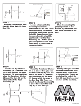
Replacing the Panel Fasteners
1. Remove fasteners securing left front corner of floor
panel and left end of access panel to frame (Fig. 4).
1
2
Figure 4
1. Floor panel 2. Access panel
2. Replace floor panel fastener with flange head capscrew
(5/16 x 5/8 in.) supplied in loose parts (Fig. 4).
3. Replace access panel fastener with flange head
capscrew (5/16 x 3/4 in.) supplied in loose parts
(Fig. 4).
Checking the Tire Pressure
The tires are over-inflated for shipping. Therefore, release
some of the air to reduce the pressure. Correct air pressure
in the front and rear tires is 10–15 psi.
Important Maintain even pressure in all tires to ensure
uniform contact with turf.
Installing the Cutting Units
1. Remove cutting units from cartons. Assemble and
adjust per the Operator’s Manual for the cutting unit.
2. If baskets will be installed, use chart below (Fig. 5) to
determine locations at which basket guides or basket
brackets must be mounted to cutting unit carrier frames.
If baskets are not to be installed, proceed to step 5.
L.H.
FRONT
L.H.
REAR
R.H.
FRONT
R.H.
REAR
CENTER
BASKET
BRACKET
BASKET
GUIDE
BASKET
GUIDE
BASKET
GUIDE
BASKET
GUIDE
BASKET
BRACKET
BASKET
BRACKET
BASKET
BRACKET
Figure 5
3. Mount a basket guide (Fig. 6) to the appropriate side of
each cutting unit carrier frame (see Figure 7) with a
capscrew (5/16 x 1-3/4 in.), flat washer, and lock
washer or fasteners previously removed, as shown in
Figure 6.
1
2
Figure 6
1. Carrier frame 2. Basket guide
4. Install a roll pin (Fig. 7) into hole in appropriate side of
each cutting unit carrier frame (Fig. 5).
1
2
3
4
Figure 7
1. Carrier frame
2. Roll pin
3. Basket bracket
4. Basket collar

17
5. Align the mounting shaft of the cutting unit with the
pivot tube on the carrier frame. Insert the shaft into the
tube (Fig. 8).
1
2 3 4
5
6
Figure 8
1. Cutting unit mounting
shaft
2. Carrier frame pivot tube
3. Thrust washer
4. Flat washer
5. Lock washer
6. Capscrew
6. Secure shaft in pivot tube with a thrust washer, flat
washer, lock washer, and capscrew (Fig. 8).
7. Assemble the mounting nuts for the reel drive motor to
each cutting unit (Fig. 9). Leave approximately 1/2 in.
of threads exposed on each mounting stud.
8. Coat the spline shaft of the motor with clean grease and
install the motor by rotating the motor clockwise so the
motor flanges clear the studs. Rotate the motor
counterclockwise until the flanges encircle the studs and
tighten the mounting nuts. Ensure that the washers are
against the nuts.
1
2
Figure 9
1. Reel drive motor 2. Mounting nuts
9. Detach chain from lift arm and secure it to cross tube on
each rear cutting unit with a capscrew, flat washer, and
locknut (Fig. 10).
1
Figure 10
1. Lock-up chain
Important Make sure that all hydraulic hoses are
routed away from cutting unit so when cutting unit pivots
excessive rubbing does not occur.
10. Check adjustment of lock-up rollers (Fig. 11). When
properly adjusted, they will contact the lock-up levers
on rear lift arms and support the cutting units when
fully raised.
1
2
Figure 11
1. Lock-up rollers 2. Lock-up levers
11. Mount a basket to each cutting unit carrier frame by
inserting basket mounting pin into basket bracket and
depressing opposite mounting pin into pivoting bracket.

18
Adjusting the Turf
Compensation Spring
Note: This adjustment is needed for Cutting Unit Models
03527 and 03528 only.
The turf compensation spring (Fig. 12), connecting carrier
frame to cutting unit, controls the amount of fore-aft
rotation available.
The Turf Compensation Spring also transfers weight from
the front to rear roller. (This helps to reduce a wave pattern
in the turf, also known as bobbing.)
Important Make spring adjustments with cutting unit
mounted to traction unit and lowered to shop floor.
1. Tighten locknut on rear of spring rod until the gap (C)
between rear of spring bracket and front of washer is
1.25 in. (32 mm) (Fig. 12).
2. Tighten hex nuts on front end of spring rod until the
compressed length (A) of spring is 6.25 in. (328 mm)
(Fig. 12).
Note: As compressed spring length (A) decreases, weight
transfer from front roller to rear roller increases and carrier
frame/cutting unit rotation angle (B) decreases.
Note: As gap (C) between spring bracket and washer
increases, carrier frame/cutting unit rotation angle (B)
increases.
“C”
“A”
“B”
Figure 12
Lifted Height of Outer Front
Cutting Units (Enable Position)
The turnaround height of the front outer cutting units (#4 &
#5) may be increased to provide additional ground
clearance on contoured fairways. Contact your distributor
for assistance.
Note: The RM CONFIG time delay should not be changed
from the original setting of 0 when using this method to
adjust turn around height.
To increase the turn around height of the front cutting units
proceed as follows:
• Position machine on a level surface, lower the cutting
units and stop the machine.
• Loosen the carriage bolt nut securing the lift arm switch
bracket to the No. 4 lift arm (left front) (Fig. 13).
• Move the lift switch bracket inward in the slot until the
desired position is attained.
• Set the distance between the lift arm switch and the flag
on the lift arm to approximately .062 inches.
• Tighten the carriage bolt nut.
1
2
3
Figure 13
1. Lift arm switch
2. Carriage bolt nut
3. Lift arm flag

19
Installing the Rear Weight
The Reelmaster 5200-D & 5400-D Traction Units comply with CEN standard EN 836:1997, ISO standard 5395:1990, and
ANSI B71.4-1999 Standards when equipped with rear weight and 90 lb. of calcium chloride ballast is added to rear wheels.
Use chart below to determine combinations of weight required. Order parts from your local Authorized Toro Distributor.
Rear Weight
Required
Weight Part
Number
Weight Description Qty.
2wd Traction Unit with ROPS
w/o baskets
291 lb. 75-6690 Rear Weight Kit 3
2wd Traction Unit with ROPS
with baskets
358 lb. 75-6690 Rear Weight Kit 4
2wd Traction Unit w/o ROPS
w/o baskets
157 lb. 75-6690 Rear Weight Kit 1
2wd Traction Unit w/o ROPS
with baskets
224 lb. 75-6690 Rear Weight Kit 2
4wd Traction Unit with ROPS
w/o baskets
157 lb. 75-6690 Rear Weight Kit 1
4wd Traction Unit with ROPS
with baskets
249 lb.
75-6690
98-9780
Rear Weight Kit
Rear Weight Kit—25 lb.
2
1
Important If a puncture occurs in a tire with calcium chloride, remove unit from turf area as quickly as possible. To
prevent possible damage to turf, immediately soak affected area with water.

20
Before Operating
If you leave the key in the ignition switch, someone
could accidently start the engine and seriously
injure you or other bystanders.
Remove the key from the ignition switch and lower
the cutting units to the ground before servicing or
making adjustments to the machine.
Caution
Checking the Engine Oil
The engine is shipped with oil in the crankcase; however,
the oil level must be checked before and after the engine is
first started.
Crankcase capacity is approximately 4 qt. (2.8 l) with the
filter.
Use high-quality engine oil that meets the following
specifications:
API Classification Level Required: CH–4, CI–4 or
higher.
Preferred oil: SAE 15W–40 (above 0_ F)
Alternate oil: SAE 10W–30 or 5W–30
(all temperatures)
Toro Premium Engine oil is available from your distributor
in either 15W–40 or 10W–30 viscosity. See the parts
catalog for part numbers.
1. Park machine on a level surface, stop engine, and
remove key from ignition switch. Open hood.
2. Remove dipstick, wipe clean, and reinstall dipstick.
Remove dipstick and check oil level on dipstick; Oil
level should be up to FULL mark (Reelmaster
5200—Fig. 14, Reelmaster 5400—Fig. 15).
1
2
Figure 14
1. Dipstick 2. Oil fill cap
1
2
Figure 15
1. Dipstick 2. Oil fill cap
3. If oil is below FULL mark, remove fill cap and add oil
until level reaches FULL mark on dipstick. Do not
overfill.
4. Install oil fill cap and close hood.
Important Be sure to keep the engine oil level between
the upper and lower limits on the oil gauge. Engine failure
may occur as a result of over filling or under filling the
engine oil.
Checking the Cooling System
Clean debris off screen, oil cooler and front of radiator
daily, more often if conditions are extremely dusty and
dirty; refer to section on Engine Cooling System.
The cooling system is filled with a 50/50 solution of water
and permanent ethylene glycol anti-freeze. Check level of
coolant in expansion tank at beginning of each day before
starting the engine. Capacity of cooling system is 9.6
quarts.
If the engine has been running, the pressurized,
hot coolant can escape and cause burns.
• Do not open the radiator cap when the engine is
running.
• Use a rag when opening the radiator cap, and
open the cap slowly to allow steam to escape.
Caution
1. Check level of coolant in expansion tank (Fig. 16).
Coolant level should be between the marks on side of
tank.
/