Electro-Voice EVA-2082S/920 User manual
- Category
- Soundbar speakers
- Type
- User manual
This manual is also suitable for

Electro-Voice® EVA Series User Manual
EVA Series
User Manual
EVA-2082S/906
EVA-2082S/920
EVA-2082S/126
EVA-2082S/1220

Electro-Voice® EVA Series User Manual
Table of Contents
Rigging-Safety Warning ....................................................................................................................................................3
1.0 Introduction ..................................................................................................................................................................4
2.0 Tool List ......................................................................................................................................................................7
3.0 Designing an EVA Array ...........................................................................................................................................7
3.1 Applications for which EVA Arrays are Most Appropriate ...................................................................7
3.2 Typical Number of Arrays .............................................................................................................................7
3.3 Determining EVA Array Configuration with EVADA
TM
(EVA Design Assistant) Software .............8
3.4 Other Design Examples ............................................................................................................................ 14
3.41 Dealing with the Relatively High Low-Frequency Variation of Short Arrays.................. 14
3.42 A Five-Module Array Example .................................................................................................. 15
3.43 An Eight-Module Array Example ............................................................................................. 16
4.0 Preparing EVA Modules for Installation ................................................................................................. 17
4.1 Recommended Preflight Procedures .................................................................................................... 17
4.2 Module Configuration ................................................................................................................................ 17
5.0 EVA Rigging System ............................................................................................................................................... 20
5.1 Overview of the EVA Flying System ....................................................................................................... 20
5.2 Deciding which Grid Configuration to Use with an EVA Array ........................................................ 21
5.21 Standard Grid with or without Second Spreader Bar ....................................................... 21
5.22 Extended Grid with or without Second Spreader Bar ....................................................... 22
5.23 Use of Two Standard Grids ...................................................................................................... 23
5.3 Assembling and Flying an EVA Array ..................................................................................................... 24
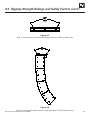
6.0 Rigging-Strength Ratings and Safety Factors .................................................................................................. 25
6.1 Working-Load Limit and Safety Factor Definitions ............................................................................. 25
6.2 Structural-Rating Overview ...................................................................................................................... 26
6.3 Simplified Structural-Rating Guidelines ................................................................................................ 27
6.4 Electro-Voice Structural-Analysis Procedures .................................................................................... 30
7.0 Rigging Inspection and Precautions ................................................................................................................... 31
8.0 References ................................................................................................................................................................ 32
8.1 Rigging (Printed) ........................................................................................................................................ 32
8.2 Mechanical Engineering (Printed) .......................................................................................................... 32
8.3 Rigging (Websites) .................................................................................................................................... 33
Notes .................................................................................................................................................................................. 34
2

Electro-Voice® EVA Series User Manual
Rigging-Safety Warning
3
This document details general rigging practices appropriate to the entertainment industry, as they would
apply to the rigging of Electro-Voice EVA loudspeaker systems. It is intended to familiarize the reader with
standard rigging hardware and techniques for suspending EVA loudspeaker systems overhead. Only per-
sons with the knowledge of proper hardware and safe rigging techniques should attempt to suspend any
sound systems overhead. Prior to suspending any Electro-Voice EVA loudspeaker systems overhead, it is
essential that the user be familiar with the strength ratings, rigging techniques and special safety consid-
erations outlined in this manual. The rigging techniques and practices recommended in this manual are, of
necessity, in general terms to accommodate the many variations in loudspeaker arrays and rigging con-
figurations. As such, the user is expressly responsible for the safety of all specific EVA loud-
speaker array designs and rigging configurations as implemented in practice.
All the general rigging material contained in this manual is based on the best available engineering infor-
mation concerning materials and practices, as commonly recognized in the United States, and is believed
to be accurate at the time of original printing. As such, the information may not be directly applicable in
other countries. Furthermore, the regulations and requirements governing rigging hardware and practices
may be superseded by local regulations. It is the responsibility of the user to ensure that any Electro-Voice
loudspeaker system is suspended overhead in accordance with all current federal, state and local regula-
tions.
All specific material concerning the strength ratings, rigging techniques and safety considerations for
the EVA loudspeaker systems is based on the best available engineering information concerning the use
and limitations of the products. Electro-Voice continually engages in testing, research and development
of its loudspeaker products. As a result, the specifications are subject to change without notice. It is the
responsibility of the user to ensure that any Electro-Voice loudspeaker system is suspended overhead in
accordance with the strength ratings, rigging techniques and safety considerations given in this docu-
ment and any manual update notices. All non-Electro-Voice associated hardware items necessary to rig a
complete EVA loudspeaker array (chain hoists, building or tower supports and miscellaneous mechanical
components) are the responsibility of others.
Electro-Voice
December 2008

Electro-Voice® EVA Series User Manual
1.0 Introduction
The Electro-Voice® EVA (Expandable Vertical Array) loudspeaker systems or line-array modules represent
an important step in line-array technology for small- and medium-scale fixed-installation sound reinforce-
ment. The four models are designed to significantly simplify the physical assembly of a line array. Also,
arrays of EVA modules are designed to be powered from one amplifier channel, the necessary crossover
and EQ functions accomplished with sophisticated passive networks. The individual loudspeaker drivers,
Hydra™ plane-wave generators, acoustic waveguides, enclosures and rigging hardware were all designed
specifically for the EVA product line to not only achieve the highest acoustic output with the highest fidel-
ity but also produce a precise wavefront from each element to achieve state-of-the-art line-array perfor-
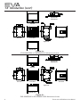
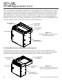
mance. A brief description of the product line is included below. The EVA modules are shown in Figure 1
with key dimensions and features.
Although the EVA modules shown in Figure 1 are not physically symmetrical, their acoustic polar respons-
es are substantially symmetrical. Thus, stereo left and right arrays or left-center-right arrays may be con-
structed with the modules in their normal right-side-up orientation as shown in Figure 1. However, should
the user desire, the module attachment points are such that mirror-image left-right arrays can be made by
constructing one array with its modules turned upside down with respect to the views of Figure 1.
Each EVA module contains two separate, vertically stacked line-array elements.
EVA-2082S/906: two-way, LF/HF line-array module with a 90° horizontal x 6° vertical coverage pattern
(for long throws) and passive crossover/HF-shading/EQ network. The enclosure is trapezoidal in the verti-
cal plane with a 6° total included angle. The two line-array elements contained in the module are vertically
splayed by 3°.
EVA-2082S/920: two-way, LF/HF line-array module with a 90° horizontal x 20° vertical coverage pat-
tern (for short throws) and passive crossover/HF-shading/EQ network. The enclosure is trapezoidal in
the vertical plane with a 20° total included angle. The two line-array elements contained in the module are
vertically splayed by 10°.
EVA-2082S/126: two-way, LF/HF line-array module with a 120° horizontal x 6° vertical coverage pattern
(for long throws) and passive crossover/HF-shading/EQ network. The enclosure is trapezoidal in the verti-
cal plane with a 6° total included angle. The two line-array elements contained in the module are vertically
splayed by 3°.
EVA-2082S/1220: two-way, LF/HF line-array module with a 120° horizontal x 20° vertical coverage pat-
tern (for short throws) and passive crossover/HF-shading/EQ network. The enclosure is trapezoidal in
the vertical plane with a 20° total included angle. The two line-array elements contained in the module are
vertically splayed by 10°.
EVA-AM: this optional attenuation module mounts on the inside of an EVA input panel, and attenuates the
entire module by 3, 6 or 9 dB. The nominal impedance of an EVA module is 16 ohms. Up to six paralleled
EVA modules can be driven from a single amplifier channel capable of driving a 2.7-ohm nominal imped-
ance (16 ohms ÷ 6 modules = 2.7 ohms).
4

Electro-Voice® EVA Series User Manual 5
1.0 Introduction (cont’)
Up to eight paralleled modules can be driven from a single amplifier channel capable of driving a 2.3-ohm
nominal impedance if at least two of the modules have the optional EVA-AM attenuation modules installed.
All EVA modules contain two vertically stacked EVS2008 8-inch (203 mm) LF drivers and two pairs of
DH2005 1.25-inch-diaphragm (32 mm) HF drivers. Each driver pair is mounted on a Hydra™ plane-wave
generator, the two of which are vertically stacked. The internal shading network can attenuate either the
upper or lower HF driver pair by 3 dB.
The standard EVA indoor versions are finished in tough EVCoat™. In addition, all EVA modules are avail-
able in two levels of weather resistance. The FG versions, e.g., EVA-2082/906-FGB, are designed for full
weather exposure and feature a fiberglass-finished enclosure, stainless-steel hydrophobic grille and the
CDG dual-gland-nut input-panel cover. The PI versions, e.g., EVA-2082S/906-PI, are rated for indirect
outdoor exposure only in protected areas, such as under a roof overhang, and feature a stainless-steel hy-
drophobic grille and CDG dual-gland-nut input-panel cover on an enclosure finished in standard EVCoat.
External fasteners on all EVA systems are stainless steel.
All EVA modules are available in black or white and are supplied with the hardware necessary to fasten
one module to another and two cosmetic end caps, which give the finished array a smooth and unclut-
tered appearance. (The end caps on FG fiberglass versions are also finished in fiberglass.) Black is indi-
cated by BLK or B at the very end of the complete model number and white is indicated by WHT or W at
the very end of the complete model number, e.g., EVA-2082S/906-BLK and EVA-2082S/906-PIB.
EVA-SG-BLK and EVA-SG-WHT: standard grids for typical down angles with small arrays, or top and
bottom suspension for extreme down angles in large arrays.
EVA-EG-BLK and EVA-EG-WHT: extended grids for extreme down angles in small to medium arrays
and typical down angles in large arrays.
The two different grid options (EVA-SG and EVA-EG) are sold separately. Consult EVADA software
for proper grid selection.
EVA-GXB-BLK and EVA-GXB-WHT: optional second spreader bars for the standard and extended
grids, to be used when two-point front-to-back hangs are desired. Note: the need to maintain sufficient
pressure on the forward rigging point will limit the amount of down angle available with the standard
EVA-GRID in this configuration.
CDG: optional dual-gland-nut input-panel cover to protect the input connections from water. Note that
this cover is supplied with the weather-resistant versions of EVA modules.
CSG: optional single-gland-nut input-panel cover to protect the input connections from water.
CDNL4: optional input-panel cover equipped with dual Neutrik Speakon® NL4M connectors, providing a
quick-disconnect alternative to the standard Phoenix screw-terminal input connectors.

Electro-Voice® EVA Series User Manual6
1.0 Introduction (cont’)
Figure 1a:
EVA-2082S/906 or EVA-2082S/126 dimensioned views
Figure 1b:
EVA-2082S/920 or EVA-2082S/1220 dimensioned views
Bottom View
Front View
Top View
Left View
Right View
Rear View
Spreader Bar
Attach Holes
Bottom View
Front View
Top View
Left View
Right View
Rear View
Spreader Bar
Attach Holes

Electro-Voice® EVA Series User Manual 7
2.0 Tool List
Listed below are the tools required to assemble an EVA array:
1. Phillips #2 screwdriver (for attaching cosmetic end panels).
2. 6-mm Allen (hex) wrench (for attaching tie plates and assembling grids).
3. 3/16-inch flat-blade screwdriver (for attaching signal wires to input-panel connectors).
3.0 Designing an EVA Array
3.1 Applications for Which EVA Arrays Are Most Appropriate
The total included vertical angles of the EVA modules in side view (6° for long throw and 20° for short
throw) were determined after making many array simulations with the EVA Design Assistant (EVADA™)
software (described in some detail below). Optimum maximum throw distance for uniform front-to-back
coverage is 100 ft ±25 ft.
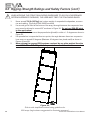
In side view, a quick rule of thumb for aiming a three- or four-box array in a venue with a flat floor is to have
a line running through the intersection of the top two modules intersect the head of the person in the last
row. This situation is shown in Figure 2.
3.2 Typical Number of Arrays
Line-array systems usually consist of vertical columns of multiple independent line-array elements. The
most common implementation is probably a stereo sound reinforcement system with two columns (left
and right). Additional columns are sometimes added to cover different seating sections of a venue, e.g.,
seating areas that wrap around the side or back of a stage. An additional column is also used in left-cen-
ter-right configurations, with the center channel for speech. In some venues, where stereo is not desired,
good coverage can be obtained with a singe array. A variation of such a monaural system is the exploded
array, where two or more widely spaced (on the order of 10 ft or more) arrays are used to provide the
horizontal coverage required. Also, a large number of arrays may be used in distributed systems, such as
in an arena.
Figure 2:
Rule-of-thumb for aiming three- and four-module EVA arrays

Electro-Voice® EVA Series User Manual8
3.0 Designing an EVA Array (cont’)
3.3 Determining EVA Array Configuration with EVADA™ (EVA Design Assistant) Software
EVADA™ is Excel-spreadsheet-based software for determining optimum array configurations for a given
venue and trim heights. The latest version of EVADA is downloadable from the Electro-Voice Web site
(www.electrovoice.com).
Briefly, one models the room along the horizontal aiming axis of the array, then builds the array of long-
and/or short-throw modules that produces the most even coverage front to back. (As described above,
EVA modules come in two horizontal coverage angles, 90° and 120°. Following industry convention, these
angles are defined where output is 6 dB down from the maximum [usually on axis] output. Chose the hori-
zontal angle that provides good coverage of the audience in plan view but minimizes energy directed on
reflective wall surfaces, which energizes the room and lowers the intelligibility of the sound system.)
EVADA displays coverage in three frequency bands. The default bandwidth is one-third octave. The de-
fault frequencies are 500 Hz, 3,000 Hz and 8,000 Hz. 3,000 Hz is very important for voice intelligibility.
8,000 Hz is important for “sparkle.” 500 Hz (and below) is important for maintaining a good spectral bal-
ance throughout the venue. Longer arrays provide low-frequency uniformity closer to the mid- and high-
frequency performance of the array. These effects can be easily seen in EVADA. In addition, the frequen-
cies and bandwidths can be modified by the designer.
EVADA includes an extensive help file but the following overview will provide a good introduction.
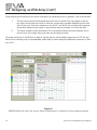
Figure 3 shows the Venue tab of the EVADA spreadsheet, where the room information is entered, includ-
ing dimensions, head height, stage specs (optional) and the so-called “acoustic reference point.” This is
the point in the venue where EVADA makes its sound-pressure level (SPL) calculations. The acoustic-ref-
erence point is typically the mixing position. If uncertain, enter a position in the middle of the main cover-
age area.
Figure 3:
EVADA
TM
Venue tab, where room information is entered

Electro-Voice® EVA Series User Manual 9
3.0 Designing an EVA Array (cont’)
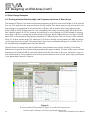
Figure 4 shows the EVADA Main tab, where the array is built and its performance evaluated in the three
frequency bands mentioned above. This tab is full of information and things to enter:
1. In the top middle of the view is where the number of suspension points (one or two, front to
back), array trim height and distance downstage from front of rig are chosen. Regarding trim
height, be sure to allow for the height of the lifting mechanism(s) and attachment points.
2. At the top right of the view is where the three frequency bands and their bandwidths are
shown. The default bandwidth is 0.33 octave and the default frequencies are 3,000 Hz, 500
Hz and 8,000 Hz. These can be changed by the user.
3. The Loudspeaker Stack column and table at the upper left allows the user to (1) pick the
standard or extended grid (click on the default grid cell to access a selection menu), (2)
adjust the grid tilt angle, and (3) pick any of the four EVA modules up to eight in number.
The HF Attenuator column contains cells which show the effect of the internal 3-dB high-
frequency attenuator (high-frequency shading): no attenuation or attenuation of either the
upper or lower high-frequency driver pair. The Optional Attenuator column contains cells
which show the effect of the optional EVA-AM attenuator module: 0 dB (not installed), or 3
dB, 6 dB or 9 dB (installed).
4. Once the elements of items 1 and 3 are complete, clicking on the yellow Update Prediction
button will calculate array performance. This button appears in the Main Cluster geometry
view (one is shown in Figure 9). The module vertical aiming angles are also displayed, with
a different colored, slightly splayed line pair for each module (as noted in Section 1.0, there
are two line-array elements in each EVA module, vertically splayed by 3° or 10°, depending
on model). If the Show Polars box is checked under Options, the vertical polar responses of
the array are also shown in this area, in the three frequency bands and bandwidths chosen.
The acoustic reference point described earlier is the small plus sign shown near the rear of
the seating area (approximately on the lower yellow module-aiming line).
5. The most important predicted information is shown in the Main Cluster SPL graph below
the Main Cluster Geometry view. This shows the predicted coverage uniformity front (left)
to back (right) in dB, where 0 dB is the value shown in the upper right-hand corner of the
Main Cluster SPL view. (In Figure 4, this value is 112 dB SPL.) Note that SPL prediction is
a complex function of the array maximum output versus frequency, the spectral distribution
and peak-to-average ratio of the program material, the dynamic peak capability of the power
amplifiers, and room acoustics. However, the EVADA calculated SPL value has been found
to be close to the peak indications, e.g., peak pointer readings, on a sound level meter with
C or F (flat) weighting in its fast averaging mode under the following conditions: (1) typical
broadband contemporary music program, (2) two arrays operating in a reverberant envi-
ronment and (3) using the power amplifiers recommended in the engineering data sheets
(available at www.electrovoice.com). (A one-array design would reduce the predicted SPL
by 3 dB.)

Electro-Voice® EVA Series User Manual10
3.0 Designing an EVA Array (cont’)
Producing the most uniform front-to-back coverage is an iterative process. In general, it will be found that:
1. The top-most module will be aimed above the last-row heads. This may appear to aim ar-
ray output at the back wall, which if reflective could produce audible delayed signals in the
front of the room. However, reference to the 3,000- and 8,000-Hz vertical polar responses
shows that maximum array output is aimed at the rear-most heads, not at the rear wall.
2. The lower modules will be attenuated. This is required because the lower modules are so
much closer to the seats they cover than are the upper modules.
Coverage uniformity of ±3 dB front to back is a good goal for mid and high frequencies. At 500 Hz and
below, such uniformity may not be attainable, particularly for short arrays (see additional comments in Sec-
tion 3.41).
Figure 4:
EVADA
TM
Main tab, where the array is built and performance is displayed in three frequency bands

Electro-Voice® EVA Series User Manual
Figure 5:
EVADA
TM
Picture tab
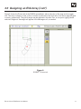
3.0 Designing an EVA Array (cont’)
Figure 5 shows the Picture tab of the EVADA spreadsheet, with a side view of the array and its suspen-
sion. The array is drawn to scale, in feet or meters as selected in the Units tab on the Venue page (English
or metric, respectively). The grid tilt angle may be adjusted in this tab. One- or two-point rigging can be
selected. Diagnostic messages will appear in the Messages cell, as needed.
11

Electro-Voice® EVA Series User Manual
3.0 Designing an EVA Array (cont’)
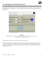
Figure 6 shows the Report tab of the EVADA spreadsheet, showing such details as hang points (in this
example, pinholes 18 and 0 on the extended grid), type of hang point (main or pullback), load (lb), mod-
ules in the array and their vertical aiming angles (note that the module inclination angle is the rear panel of
the module).
The Subwoofers tab allows the user to assemble subwoofer arrays and assess the inevitable multiple-
source interference that occurs when two or more arrays are displaced horizontally. This is done by show-
ing the horizontal polar response of subwoofer arrays at three frequencies. The default frequencies are 90,
60 and 40 Hz but can be changed. The option of changing the polarity of each subwoofer and inserting
up to 9.9 ms of delay in any one group of subwoofers is available. These options may be found to smooth
the interference patterns.
The Preferences tab allows the user to change the colors associated with each array element or module.
Refer to the Preferences help file for details.
Figure 6:
EVADA
TM
Report tab, with many physical array details
12

Electro-Voice® EVA Series User Manual
3.0 Designing an EVA Array (cont’)
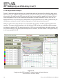
The Cable Loss tab allows the user to enter the combined impedance of an EVA array and the length and
gauge (AWG) of the wire feeding it, in order to calculate the level lost (dB) in the cable feeding the array.
See Figure 7.
Figure 7:
EVADA
TM
Cable Loss tab, calculates the dB level lost in speaker wiring as a function
of the wire gauge (AWG) and length
The Notes tab is a place to enter comments on the particular design.
The Supported Products tab shows both the EVA main array products but also Electro-Voice subwoof-
ers which are suitable for use with EVA arrays. These vary in maximum acoustic output ability and low-
frequency cut-off frequency. The Electro-Voice Web site (www.electrovoice.com) has detailed information
on the subwoofers listed.
13

Electro-Voice® EVA Series User Manual14
3.0 Designing an EVA Array (cont’)
3.4 Other Design Examples
3.41 Dealing with the Relatively High Low-Frequency Variation of Short Arrays
The example of Figure 4 is a three-module array addressing a flat floor from a trim height of 23 ft, with the
first row 10 ft away from the array and the last row 80 ft away. This design opts for very uniform mid- and
high-frequency coverage that hovers around the 0-dB line, with a variation that is well within the opti-
mum ±3 dB at 3,000 Hz (important for vocal intelligibility) and nearly as uniform (±3.5 dB) at 8,000 Hz
(the “sparkle” range). At 500 Hz, however, the uniformity is a non-optimum ±4.5 dB. Instead of hovering
around the 0-dB line, coverage has a distinct bias, rising from about 0 dB at the front to a high of +8 dB
about 25% of the way back, then falling slowly back to 0 dB at the rear. This is a function of the relatively
short, 4.7-ft three-module array. The variation at 100 Hz (not shown) is even greater (± 6 dB), and drops
continuously from front to back. This means that if the sound is well balanced up front, it will be “thin” at
the rear (although intelligibility and clarity will be fine).
Figure 8 shows the same array with a modification that provides more uniform “tracking” of the three
frequencies. In general, this is achieved by attenuating the upper modules. For most of the venue, all three
frequencies are within ±3 dB of each other. While levels fall at the rear of the room, the falloff is very uni-
form with frequency. This provides a more uniform spectral balance front to back, which may be preferred
to the performance shown in Figure 4.
Figure 8:
A three-module EVA example of Figure 4, modified to improve the
front-to-back “tracking” of all three predicted frequencies

Electro-Voice® EVA Series User Manual 15
3.0 Designing an EVA Array (cont’)
3.42 A Five-Module Array Example
Figure 9 shows another, five-module array in an 80-ft-deep venue with the front row five ft from the ar-
ray and whose floor begins to rise about halfway back. The three frequencies not only track very well but
nearly all of the venue is within ±3 dB front to back. This desirable situation is helped by not only the 3-dB
attenuation of the top module but also by the array being longer than the three-module examples above
(4.4 ft versus 7.3 ft).
Figure 9:
A five-module EVA example whose three predicted frequencies not only track well
front-to-back, but also fall mostly within the desired ±3 dB

Electro-Voice® EVA Series User Manual16
3.0 Designing an EVA Array (cont’)
Figure 10:
A eight-module EVA example in a large theater with two balconies
(see text above for more details)
3.43 An Eight-Module Example
Figure 10 shows an eight-module array in a large theater with two balconies. Note that this array cannot
be driven from one amplifier channel because only one of the modules uses the optional EVA-AM attenu-
ation module. (An eight-module EVA array can be driven from an amplifier capable of driving a 2.3-ohm
nominal impedance if two of the modules have attenuation modules installed. A solution is to use two
amplifier channels, one for the top four modules and one for the bottom four. In order to preserve the pre-
dicted array coverage, be certain that the voltage gains of both channels are the same.)
Nearly all of the 100-ft-deep main floor is covered within the optimum ±3 dB at all three predicted fre-
quencies. The same uniformity applies to the first balcony (108 ft at the rear wall) although the average
level drops by about 3 dB. The upper balcony (also 108 ft at its rear wall) shows a bit wider variation and
less uniform tracking of the three predicted frequencies. However, the total variation in the upper balcony
is still an acceptable ±4 dB.

Electro-Voice® EVA Series User Manual 17
4.0 Preparing EVA Modules for Installation
4.1 Recommended Preflight Procedures
For any installed sound system, certain checks made at the installer’s place of business can prevent ex-
pensive on-site delays. A short-list follows, and sets the stage for proper array performance:
1. Unpack all loudspeakers in the shop.
2. Check for proper model numbers.
3. Check the overall condition of the loudspeakers.
4. Check for continuity at the loudspeaker inputs.
It is a good idea, once on site and the loudspeakers are connected, to check again for continuity at the
power-amplifier end.
4.2 Module Configuration
After the EVADA software has been used to design an appropriate array, the high-frequency (HF) shading
or use of the optional attenuation modules should be noted. In this way, these settings and options can
be configured on the systems as they are rigged together and suspended. (The shading adjustments and
installation of attenuation modules can be completed at the installer’s shop but then care must be taken to
see that the EVA modules are properly identified to avoid misassembly of the array in the field.)
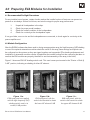
Figure 11 shows an EVA HF shading switch card. This card comes pre-inserted in the “Center = Both @
0 dB” position, indicating no shading of either HF element.
Figure 11b:
EVA input panel, with the
switch card inserted to shade
the lower HF element 3 dB
Figure 11a:
EVA input panel as supplied,
with the high-frequency (HF)
shading switch card in its
central, 0 dB position
Figure 11c:
EVA input panel, with the
switch card inserted to shade
the upper HF element 3 dB

Electro-Voice® EVA Series User Manual
4.0 Preparing EVA Modules for Installation (cont’)
To attenuate the top HF element, remove the switch card by drawing it toward you using the central finger
hole. (The switch can also be removed with the end of a flat-blade screwdriver, by placing the blade end
in the switch hole and using the adjacent edge of the input panel as a fulcrum. To facilitate this operation,
there is a small recess in the edge of the input panel adjacent to the hole in switch card.) Reinsert the
switch card one step higher to shade the upper HF element by 3 dB. Reinsert the switch card one step
lower to shade the lower HF element.
Some array designs will also use one or more of the optional EVA-AM attenuation modules. These attach
to the inside of the input-panel assembly using the following steps:
1. Remove the input-panel assembly by removing its eight holding screws with a Phillips #2
screwdriver. The cable assembly that connects the input-panel’s green PC board to the
crossover/equalizer network inside the EVA module is long enough to allow the input-panel
assembly to rest on a flat surface close to the EVA module. If necessary, the crossover/
equalizer cable can be temporarily disconnected. The removed input-panel assembly is
shown in Figure 12.
2. Unplug and discard the 7-pin jumper-wire connector. The attenuation module’s cable con-
nector will replace this connector.
3. With the mounting straps on top, place the attenuation module into the pocket between the
four bosses adjacent to the PC board and secure with the four screws (provided).
4. Plug the attenuation module’s cable into the 7-position header on the PC board as shown
in Figure 13.
5. Apply the supplied label to the input panel around the input connectors as shown on the
EVA-AM Instruction Sheet.
6. Reinstall the input-panel assembly.
7. Connect a short piece of wire (supplied) from the “SELECT” terminal to the terminal marked
-3, -6 or -9 dB, as determined by EVADA.
18

Electro-Voice® EVA Series User Manual
Figure 12:
EVA input panel removed, showing green PC board and the four bosses
to which the optional EVA-AM attenuation module will be attached
Figure 13:
EVA input panel with EVA-AM installed showing connector plug-in
4.0 Preparing EVA Modules for Installation (cont’)
19

Electro-Voice® EVA Series User Manual
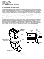
5.0 EVA Rigging System
5.1 Overview of the EVA Flying System
The external rigging parts supplied with each EVA line-array module attach to metal parts internal to each
module, so that a finished array places no stress on the wooden enclosure parts. The rigging simplification
inherent in the EVA modules is based on the final array being assembled in a fixed manner. The EVA en-
closures are vertically trapezoidal—taller at the front than at the back. One module is fastened to another
with the bottom of one in contact with the top of another. The vertical aiming angle between the two mod-
ules is fixed by their vertical draft angles. The draft angle is 3° for the EVA-2082S/906 and EVA-2082-
S/126 long-throw modules and 10° for the EVA-2082S/920 and EVA-2082S/1220 short-throw modules,
producing 6°, 13° or 20° between any two modules, depending on which modules are attached together.
(The specific selection of long- and short-throw modules and their arrangement is dependant on room ge-
ometry and trim height. These choices are facilitated by Electro-Voice’s EVA Design Assistant [EVADA™],
software available on the EV Web site, www.electrovoice.com. See section 3.0 Designing an EVA Array
above.) Each EVA module is attached to the module below it by the supplied pair of side-mounted tie
plates. After the array is assembled, cosmetic end caps, one for each side of each module, are attached
to the enclosure, hiding the structural tie plates and giving a smooth, attractive array appearance.
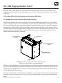
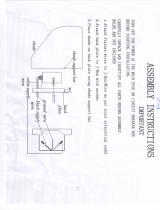
A basic array is shown in Figure 14, which illustrates the basic components that make up the EVA flying
system.
Figure 14:
Typical EVA flying system
Note: Cosmetic End
Panels Not Shown
EVA Grid
Attach Grid Side
Arms with M10 Bolts
Supplied
Attach Tie Plates with
M10 Bolts Supplied
Tie Plates
(2 Supplied with
each EVA Module)
EVA Modules
Attach Spreader Bar
with M10 Shoulder
Bolts and Nylon
Washers Supplied
with Grid
Grid Assembly Detail
M10
Shoulder
Bolt
Nylon
Washer
Grid
Side
Arm
Spreader
Bar
EVA Module
20
Page is loading ...
Page is loading ...
Page is loading ...
Page is loading ...
Page is loading ...
Page is loading ...
Page is loading ...
Page is loading ...
Page is loading ...
Page is loading ...
Page is loading ...
Page is loading ...
Page is loading ...
Page is loading ...
Page is loading ...
Page is loading ...
-
 1
1
-
 2
2
-
 3
3
-
 4
4
-
 5
5
-
 6
6
-
 7
7
-
 8
8
-
 9
9
-
 10
10
-
 11
11
-
 12
12
-
 13
13
-
 14
14
-
 15
15
-
 16
16
-
 17
17
-
 18
18
-
 19
19
-
 20
20
-
 21
21
-
 22
22
-
 23
23
-
 24
24
-
 25
25
-
 26
26
-
 27
27
-
 28
28
-
 29
29
-
 30
30
-
 31
31
-
 32
32
-
 33
33
-
 34
34
-
 35
35
-
 36
36


Electro-Voice EVA-2082S/920 User manual
- Category
- Soundbar speakers
- Type
- User manual
- This manual is also suitable for
Ask a question and I''ll find the answer in the document
Finding information in a document is now easier with AI
Related papers
-
Electro-Voice EVF-2151D User manual
-
-
Bosch ZX3-60PI-W User manual
-
-
-
-
-
-
-
Electro-Voice EVF-1181S Operating instructions
Other documents
-
 Amora Lighting AM249WL12 Installation guide
-
 Amora Lighting AM1056WL12 Installation guide
-
Wirepath WP-CAT78-RJ45-SHLD Installation guide
-
-
Atlas FA Series Installation guide
-
 Melard Sidearm All-Terrain Handheld PC User manual
-
 Xtant RM-4 Owner's manual
-
 Accent Builders Hardware CDG-2001CP Installation guide
-
 Excell J4 User manual
-
EAW Resolution User guide


