Page is loading ...

HELP FILE
Resolution 2

2
Table of Contents
Section 1 – Introduction ...................................................................................................................... 5
Section 2 - Menu Features ................................................................................................................... 6
File Menu ......................................................................................................................................... 6
Edit Menu ........................................................................................................................................ 7
View Menu ....................................................................................................................................... 7
Network Menu ................................................................................................................................ 8
Options Menu .................................................................................................................................. 9
Tools Menu .................................................................................................................................... 10
Help Menu ..................................................................................................................................... 11
Section 3 - Getting Around Resolution .............................................................................................. 12
The Array View Window ................................................................................................................ 12
The Venue View Window .............................................................................................................. 14
The Project Explorer Window ........................................................................................................ 17
Project Explorer Window Hierarchy .............................................................................................. 17
The Properties Window ................................................................................................................. 21
Surfaces ......................................................................................................................................... 22
Arrays ............................................................................................................................................. 23
Copy/Paste/Link Processing .......................................................................................................... 24
The Frequency Response Window ................................................................................................ 26
Section 4 - The Network Configuration View .................................................................................... 29
Parameter Synchronization Status ................................................................................................ 31
Parameter Sync Window ............................................................................................................... 32
Adaptive Systems Network ........................................................................................................... 33
Configure Dante Network Interfaces............................................................................................. 33
The Private Network ...................................................................................................................... 33

3
The DHCP Network ........................................................................................................................ 34
Dante Controller ............................................................................................................................ 35
Preset Manager ............................................................................................................................. 35
Going Online (Adaptive systems only)........................................................................................... 36
Assigning Physical Arrays/Modules to Modeled Arrays/Modules ................................................ 37
Assigning Mixed Arrays.................................................................................................................. 39
Managing Arrays ............................................................................................................................ 40
Assigning Inputs ............................................................................................................................. 42
Selecting Analog or AES Input ....................................................................................................... 44
Selecting the Net or Net Aux Input................................................................................................ 45
Adaptive Systems Diagnostics Window ......................................................................................... 46
The Overview Tab .......................................................................................................................... 46
The Meters Tab .............................................................................................................................. 47
The Maintenance Tab .................................................................................................................... 47
The Temp Log Tab ......................................................................................................................... 48
The Impedance Log Tab ................................................................................................................. 48
The Error Log Tab .......................................................................................................................... 49
The Acoustic Measurements Tab .................................................................................................. 50
System Health ................................................................................................................................ 51
Going Online (UX/UXA Processors & Amplifiers) .......................................................................... 53
UX/UXA Input Section.................................................................................................................... 58
....................................................................................................................................................... 58
UX/UXA Output Section ................................................................................................................. 59
....................................................................................................................................................... 59
Loading Greyboxes (UX/UXA Processors & Amplifiers) ................................................................. 60
Section 5 - Entering 3D Audience Areas ............................................................................................ 64
Modeling Basics ............................................................................................................................. 64

4
Editing Surfaces ............................................................................................................................. 65
Surfaces (Polar Data Entry Mode) ................................................................................................. 66
Options for Adding a New Surface ................................................................................................ 68
Adding A Balcony (Polar Data Entry Mode) ................................................................................... 69
Front of House Position ................................................................................................................. 71
Adding a Stage (Polar Data Entry Mode) ....................................................................................... 71
Adding Sides (Polar Data Entry Mode) .......................................................................................... 72
Adding Corners (Polar Data Entry Mode) ...................................................................................... 75
Entering Surfaces – Alternate Methods ........................................................................................ 77
Surfaces (Laser Data Entry Mode) ................................................................................................. 78
Adding Sides (Laser Data Entry Mode) .......................................................................................... 79
Adding Corners (Laser Data Entry Mode) ...................................................................................... 80
Image Import ................................................................................................................................. 81
Saved Acoustic Models (SPL Map & Adaptive Settings) ................................................................ 86
Section 6 - Working With Arrays ....................................................................................................... 88
Adding an Array - Launching the Array Assistant .......................................................................... 88
Array Settings Page ........................................................................................................................ 89
Coverage Goals page ..................................................................................................................... 91
Modifying an Array via the Array Assistant ................................................................................... 93
Differences between Traditional Line Arrays and Anya/Anna Arrays in the Assistant ................. 93
Working with Anya and Anna in the Model .................................................................................. 94
Spatial EQ ....................................................................................................................................... 95
Air Loss Compensation and Adaptive Arrays ................................................................................. 97
Working with Otto in the Array Assistant ................................................................................... 100
Working with Otto in the Properties Window ............................................................................ 102
Working with Otto in the Array View Window............................................................................ 103
Going Online With Otto ............................................................................................................... 104

5
Using Mixed Adaptive Arrays ...................................................................................................... 106
Find Me (Trilateration) ................................................................................................................ 108
Section 7 - Appendix ........................................................................................................................ 112
Anya/Anna Voicings ..................................................................................................................... 112
Exporting from Resolution into EASE .......................................................................................... 115
Upgrading Firmware on Adaptive Modules ................................................................................ 120
Contacting EAW ............................................................................................................................... 123
Operating Questions.................................................................................................................... 123
General ........................................................................................................................................ 123
Section 1 – Introduction
EAW Resolution™ 2 is a tool to assist sound system designers and engineers to select,
configure, and implement EAW loudspeaker products. Resolution™ 2 predicts direct sound
pressure level (SPL) in a ‘virtual’ venue. Signal processing can be applied in software, and the
resulting frequency response calculated for ‘virtual microphones’ throughout the model.
Additionally, Resolution™ 2 performs mechanical calculations for a given array or loudspeaker
configuration to assist the user in correctly rigging their sound system.
Resolution Help Videos and Tutorials can be found on the EAWVideo Youtube Channel or on
the Resolution Yoututbe Playlist.
A Note about Compatibility with Resolution™ 1 Models
Though Resolution 1.x models are displayed in two dimensions, Resolution 2 will accept and
open these files without issue. Users should expect the same acoustical results in both
software versions, but may also gain additional insight into a Resolution 1 model viewed in
Resolution 2 due to the enhanced three-dimensional viewing options available.
Due to the significantly more complex audience area data in Resolution 2, however, these files
will not open successfully in Resolution 1. If users wish to maintain Resolution 1 compatibility
for a given file, they should not save it in Resolution 2, or should maintain a separate copy of
the original file.
System Requirements
EAW Resolution 2 requires an IBM®-compatible PC with Windows 7® or Windows 8®
operating systems, including a standard Ethernet port to connect the computer to the
network and control Adaptive loudspeaker modules. Though processor speed and

6
memory size primarily impact only calculation time, the following specifications are
recommended for useful operation:
MINIMUM REQUIREMENTS
RECOMMENDED SPECIFICATIONS
Processor
2.2 GHz Dual Core Processor
2.8 GHz Quad Core Processor
Memory
2 GB RAM
8 GB RAM
Screen Resolution
1024 x 768 display resolution
1920 x 1080 display resolution
Operating System
Windows 7 / Windows 8 / Windows 10
Storage
1 GB available HD space
NOTE: Support for Windows versions earlier than 7 (XP, Vista) has been discontinued by
Microsoft. As a result, Resolution is not supported for these operating systems. Use of
parallel operating systems is not recommended or supported. A PC running Windows
natively is required.
Section 2 - Menu Features
File Menu
A Resolution File contains venue and loudspeaker information. The following options are
available from the ‘File’ drop-down menu:
New - Creates a new Resolution File (clears all data in the current model).
Open - Opens a Resolution (.eawresolution format) File, or an EAW log file (.eawlog
format)
Open Acoustic Model - Opens a saved acoustic model (*.eawcab file)
Save - Saves the current settings to currently open Resolution File.
Save As… - Saves the current settings to a Resolution File under a new name.
Save Acoustic Model - Opens dialog to save acoustic model with ADAPTive settings
Import - Used to place previously-saved .eawvenue or .eawarray files into the default
Resolution file folders. Once imported, the files can be found using the “Load Preset”
button for either venue or array.
Import Drawing – Opens the dialog window that allows for image import.
Export EASE File - Exports the current design as a file that is compatible with EASE
software (for more detail about this, see our EASE Export Tech Note)

7
Create PDF - Outputs information for each loudspeaker array utilized in a Resolution file
Create CSV - Creates a spreadsheet (readable via Excel) with all pertinent data of the
design.
Recent Files - Recall recently-used Resolution Files.
Exit - Quits the Resolution software.
Edit Menu
Undo - Undoes your last action.
Redo - Re-does your last “undone” action.
View Menu
Venue Configuration - Opens the “Venue Configuration” window, which displays the
venue and array geometry in 2D and 3D views.
Network Configuration - Opens the “Network Configuration” window, which allows access
to loudspeaker control and configuration parameters, both ‘virtual’ (offline) and online.
Free View - Changes the Venue View screen to 3D view that can be rotated with the
mouse.
Side View - Changes the Venue View screen to show X and Z axis view.
Top View - Changes the Venue View screen to show X and Y axis view
Array View Window - Toggles visibility of “Array View” window, which displays physical
configuration of array in section view.
Project Explorer Window - Toggles visibility of “Project Explorer” window, which catalogs
all loudspeaker and venue elements within the file.
Properties Window - Toggles visibility of “Properties” window, which displays all available
parameters for loudspeaker and venue objects, selected either in Project Explorer or
directly in graphical Venue Configuration window.
Array Names - Toggles visibility of array names.
Aiming Lines - Toggles visibility of green aiming lines, which extend from the central axis
of each loudspeaker until intersecting a venue surface. Adaptive arrays (Anya, Anna, Otto)
also display aiming lines. Aiming lines for Adaptive arrays are shown for each module,
though sources within a module are dispersed with a higher resolution. Adaptive aiming
lines are intended to give an approximate idea of how the array is allocated when
determining its vertical coverage.

8
Aiming Coverage Lines - Toggles visibility of red coverage lines, which indicate ‘soft
edges’ of system coverage (6dB down point).
SPL - Toggles visibility of sound pressure levels.
SPL (mic only) - Toggles visibility of sound pressure levels for microphones only.
SPL Map - Toggles visibility of sound pressure levels in free space. Note: With SPL map
disabled but SPL enabled, sound pressure levels will continue to be mapped to venue
surfaces.
Contour Lines - Toggles visibility of user selectable SPL dB down points (selected in Options
menu)
Show Sweep Lines – Displays a series of green lines showing which sections of each
surfaces are being covered
Show Venue Detection – Displays a pink line representing how the venue is being
calculated.
Frequency Response - Opens a secondary window showing the direct SPL response of your
system based on the virtual microphones placed within the model
Main Toolbar - Toggles the main toolbar on or off
File Toolbar - Toggles the file toolbar on or off
Edit Toolbar - Toggles the Edit toolbar on or off
Network Menu
Connect - Poll network for all available devices.
Refresh Network - Refreshes network connection on all available devices
Disconnect - Discontinue network polling and disconnect from any connected network
devices.
Configure – Select which Network Interface Card (NIC) to use as the primary network
interface.
Auto-Identify - Enabling the Auto Identify button will trigger the white LED indicator on
an Adaptive Module or modules in an array to turn on when selected in the Online Devices
list or in the currently assigned Adaptive module in the Venue window. Selecting a single
Adaptive Module will turn the LED on that one module, selecting an array will turn on all
the LEDS in that array. This is especially helpful when assigning the physical arrays
displayed in the Online Devices list to the arrays in the Venue model.

9
Preset Manager – Opens the Preset Manager dialog window
Upload Array Parameters - Clicking the Upload Array Parameters button will send all
signal processing including Adaptive Performance processing and user signal processing to
the appropriate Adaptive Modules. The status screen will indicate if this process completes
successfully. If an error occurs, exit the status screen and select Upload Array parameters
again.
This button will be greyed out if adaptive performance calculations are incomplete. If
calculations are complete but modules are not assigned, the button will remain clickable
but will present an error, “Please make sure loudspeakers are connected to the network
and assigned”.
Unify Processor Interfaces – If connected to a processor via DANTE & Control (ethernet),
this function communicates to Resolution this is the same device.
Options Menu
Temperature and Humidity - Set the Temperature and Humidity of your venue.
Changing these values will modify air absorption characteristics, and therefore resultant
SPL on venue surfaces. These parameters are also used in calculating air loss compensation
processing for products that support this feature.
Without Air Absorption - Toggle between an SPL calculation with and without air
absorption based on the user defined temperature and humidity values.
Auto-Adjust SPL Range - Automatically determines the difference between highest and
lowest SPL within a given file, and sets limits of SPL color scale to these values.
SPL Interpolation - Affects how quickly an SPL map is created. Available settings are:
Fastest SPL mapping is rendered in the shortest amount of time. To accomplish this,
the resolution (detail) of audience area mapping is decreased.
Normal Standard SPL resolution is used. This offers the best balance of resolution
and calculation speed.
Best SPL mapping is divided into multiple steps, beginning at low resolution and
increasing as more time elapses. This provides the user with initial data in
the shortest amount of time, but also provides higher-resolution
information if given more time.
Side View Contour Lines - Defines side view contour line SPL increments. In the side view,
contour lines are positive (increasing) increments starting with the highest SPL value on
the venue surface. Selectable in 1, 2 and 3 dB increments.

10
Top View Contour Lines - Defines top view contour line SPL increments. IN the top view,
contour lines are negative (decreasing) increments starting with the highest SPL value on
the venue surface. Selectable in 1, 2 and 3 dB increments.
Design Factor - Selects the design factor as it relates to the working load limits of a design.
Resolution uses this selection to alert the user when stresses on loudspeaker rigging
components have exceeded the selected design factor.
Note: ALWAYS READ AND ABIDE BY ALL RIGGING-RELATED WARNINGS AND
INDICATIONS, INCLUDING USER MANUAL(S) AND PRODUCT-RELATED
INSTRUCTIONS AND LABELS. FAILURE TO DO SO MAY RESULT IN INJURY OR DEATH.
SI Units - All measurements are shown using the metric system
US Units - All measurements are shown using the US system.
Max SPL - SPL is measured as a maximum output per passband of a loudspeaker. In
practice this may result in an unusual tonal response since each passband is driven to its
maximum output independently (i.e. if low-frequency components in a bi-amp system are
capable of 6 dB more output than high-frequency components, the LF passband will display
as 6 dB higher). Max SPL is used as the default setting as it correctly demonstrates the
maximum output capabilities of the system.
Flat SPL - SPL is measured as the greatest output of a loudspeaker while maintaining a
consistent broadband tonal response. Processing is included in this calculation, but
Resolution does not permit equalization or gain to boost modeled output above a
loudspeaker’s actual output capabilities (i.e. a loudspeaker capable of 130 dB SPL at 1
meter cannot be ‘turned up’ to 135 dB SPL with a +5 dB gain adjustment).
ADAPTive Venue Detection Method – Toggles between adjusting vertical coverage to
extend to the sides of a venue (Wide) or to keep coverage focused to surfaces directly
in front of array (Narrow).
Tools Menu
Recalculate - Recalculates the SPL map on the defined audience plane.
Set Global Ear Height – Changes the ear height of every surface in the model (floor, seated,
standing).
Find Me (Trilateration) - Trilateration provides users with the ability to “map” a venue in
3D utilizing only two Anya arrays, a computer running both Resolution and Smaart, and a
measurement microphone.
Inventory Manager - Defines which EAW products are included in available loudspeaker
models under the Array Assistant. This is particularly useful for rental firms, as it allows the
product list to be narrowed to match their inventory.

11
Under this window, users can also view the release notes for a product and access web-
based data (requires an internet connection) via a hyperlink. Select from the list of
Resolution-supported products available in your inventory. Unselected products will
not appear in the property pane for use when building arrays.
Firmware Manager - When online, polls devices on the network for their firmware options
and provides means to update firmware when necessary.
Automatically Check For Updates - When selected, Resolution automatically checks for
updates every time the software is started. The computer must have internet access for
updates to be downloaded. To ensure that Resolution is automatically kept as up-to-date
as possible, it is recommended that users enable this setting.
Check for Updates - Regardless of status of “Automatically Check For Updates” option,
Resolution will immediately check for updates when this is selected.
Keyboard Shortcuts - Allows user to confirm and/or modify keyboard shortcuts, or restore
defaults.
Help Menu
Help - Displays this help file.
About - Displays the version of the software.

12
Section 3 - Getting Around Resolution
Resolution is segmented into four major sections or “panes”:
Array View
Venue View
Project Explorer
Properties
Note: The relative size of each pane can be easily adjusted by dragging the borders between
panes.
The Array View Window
Pane Overview
The Array View is located on the left side of the main Resolution window. This section
of the software displays a side view of the currently-selected array, and includes
information about suspension points and stresses on each critical point within an
array’s rigging.
At the bottom of this window, users can also find information about the array height,
depth, vertical aim angle, and overall weight (including flybars). The information in this
pane corresponds to the array selected from the tabs in the Property Pane.
This Pane also displays the Design Factor used for the Resolution file, displays the array
on a dimensioned grid, and allows access to an Auto Design feature for quick generation
of a basic array.
Arrays are displayed in profile (side view). If a specific array element is currently
selected, it is highlighted in blue.
The gray and blue lined grid in the background is a reference for real-world distances in
the venue. An array is displayed with X and Y axis origins at (0,0) defined by the pick
point at the fly bar. Line arrays are built from 1 or more items selectable and
manipulated from the Properties Pane.
Mechanical Loads
For each array element (flybars, adapter bars, or loudspeakers), mechanical loads are
calculated for each connection point to determine if the configuration is safe for
suspension. Acceptable loads (within the user-specified Design Factor) are highlighted
in green. Loads which approach stress limits are highlighted in yellow. Loads which
exceed stress limits are highlighted in red. The actual load (in pounds or kilograms,
depending on which unit system is selected) can be viewed by hovering the mouse over
it.

13
NOTE: It is the user’s responsibility to ensure that rigging above the flybar (also
referred to as “above the hook”) is suitable for suspension of the stated loads.
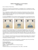
Several other features of the Array View are called out in the image below.
Note: For clarification on the labeling of pin assignments for your specific product, consult
your product’s Owner’s Manual.
Front pin
assignments
Rear pin
assignments
Flybar
suspension
point position
Pullback
(if used)
Currently-
selected
loudspeaker
Connection
point load
status
Array
Mechanical
Summary

14
The Venue View Window
The Venue View provides a visual representation of the loudspeaker arrays, venue
geometry, and sound pressure level (SPL) mapping for a given system. Resolution can
display this information in three different ways.
Top View
SPL is mapped onto each surface as viewed from directly above (“in plan”). In this mode, it
is possible to zoom in or out, as well as scroll horizontally (in both the X- and Y-axis) by
simply clicking and dragging. Take care not to click and drag an audience area or
loudspeaker while navigating.
Side View
SPL is mapped onto a cross-sectional ‘slice’ through the venue, as seen from the side (“in
section”). The location (y-coordinate) of the ‘slice’ is defined by a field in the top-right
corner of the window. In this mode, it is possible to zoom in or out, as well as to scroll
horizontally and vertically (in the X- and Z-axis, respectively) by simply clicking and
dragging. While in this view, users can select which Y-axis “slice” to view by manipulating
the “Y:” value in the upper right-hand corner. Surfaces currently intersecting the Y-axis
“slice” will be displayed with a thick blue outline, while those that do not are displayed
with a thin blue outline.

15
Free View
SPL is mapped onto each surface area, viewed in 3D. Users can manipulate the exact
vantage point by using the mouse in combination with keyboard. In this mode, it is possible
to zoom in or out, as well as to ‘orbit’ a center point in 3D by clicking and dragging. By
holding the “Shift” key while clicking and dragging, this point can be shifted around the X-
Y (horizontal) plane.
In all three views, the user can zoom in or out by using the toolbar buttons or the scroll
wheel on the mouse (if the computer is so equipped). Additionally, the X, Y, and Z axes are
color-coded (X is red, Y is green, Z blue) and labeled with text in all three views for easy
identification.
SPL Scale
On the right side of all three view modes, the SPL scale is displayed. Values range from low
(bottom, dark blue) to high (top, bright red). The limits of the scale and therefore the
resolution (dB of change per color change) are variable, however. To automatically set the
range of the scale to the range of SPL in the current prediction, the user may use the “Auto-
Adjust SPL Range” function (under the “Options” menu, or by pressing “A” with default
keyboard shortcuts). For manual control, single-click on the SPL scale.

16
Main Toolbar
A toolbar is also provided at the top of the window, allowing a number of Venue Window
functions to be quickly accessed:
File and Edit Toolbar
Two optional toolbars are available allowing access to additional quick access functions:
File Toolbar Edit Toolbar
Select Free
View mode
Select Side
View mode
Lock Surfaces
& Arrays
Reset
View
Zoom
In
Unsolo All
Arrays
Switch to
Design View
(currently
selected)
Switch to
Network View
Toggle SPL
On/Off
Add an
Array
Undo
Redo
Create New
Project
Open an
existing Project
Save
Project
Select Top
View mode
Zoom
Out
Hide All
Surfaces
Clear All
Mics
SPL
(mic only)
Add Surface

17
The Project Explorer Window
The Project Explorer Window provides a summary of all audience areas and EAW
loudspeakers in the current model.
Project Explorer Window Hierarchy
This pane utilizes a tree organizational structure to allow the user to select which details
are visible at any given time. The hierarchy of objects within ‘Arrays’ and ‘Venue’ are as
follows:
Arrays
Array 1 [Example: Line Array]
Array 1, Module 1
Array 1, Module 2
Array 1, Module 3
…
Array 2 [Example: Anya Array]
Column 1
Column 1, Module 1
Column 1, Module 2
Column 1, Module 3
…
Column 2
Column 2, Module 1
Column 2, Module 2
Column 2, Module 3
…
Notice that when users employ an Adaptive array, Resolution provides an additional sub-
category of information, since each array can include multiple columns with each column
containing a flybar and number of modules. Mechanically-articulated line arrays, on the
other hand, only ever employ one column per array.

18
Project Explorer Window Buttons
When the window is ‘popped out’, it can be placed anywhere on the screen. In addition to
clicking on the button, users can also simply drag the window to a different location on the
screen. The window can be ‘popped in’ or docked by dropping it into the ribbon on either
side of the Venue window.
Venue
Magnified View of “Venue” Heading and
Sub-headings in Project Explorer Window
Add Surface - Allows the user to input a completely new surface to the model. New
surfaces will be displayed in a “tree” format under the venue. When a new surface is
added to the model, the following options are available for that new surface in the
project explorer window.
• Clone Surface - This allows you to make a complete duplicate of any surface in the
venue tree and helps to speed up the process of building complex venues and
listening environments.
• Remove Surface - This allows the user to remove the currently selected surface. You
will be prompted before final removal of the surface.
‘Pop Out’ Window
Load a Venue Preset
Save Venue Preset
Delete Surface
Surface/Venue List
Loudspeaker/Array List
Close Window
Add Surface
Clone Surface

19
Load a Venue Preset - Allows the user to drop a preconfigured and saved venue preset
into the model. Useful for when the venue remains the same but arrays will differ from
show to show. Files are identified as .eawvenue extensions
Save Venue Preset - If the current model is a venue that the user will frequent, the room
can be saved independently as a venue file in the software and recalled at any time.
Venue files do not include any array data.
Arrays
Magnified View of “Arrays” Heading and
Sub-headings in Project Explorer Window
Upon initial start of the software, there will not be any arrays added to the model. In
the project explorer window under Arrays the user can do one of the following:
Add array - Launches the array assistant.
Save an Array Preset - Stores the array as an array file.
Load an Array Preset - Loads a previously-saved array file. Stored arrays are useful when
the system design is basically fixed but the venue will change from show to show.
Edit Array - Launches the array assistant as with Add Array, but already contains the
current settings of the array.
Add Array
Save Array
Preset
Edit Array
Delete Array
Launch
Array
Processing
Load Array
Preset
Launch
Module
Processing
Delete Array
Item
Clone Array

20
Clone Arrays - Duplicate the current array and mirror or offset it.
Launch Processing - Opens the processing window for the current array or module
(depending on which Launch Processor button is selected). Allows access to Greyboxes,
rear switch settings, parametric equalization, delay, gain, and high-pass/low-pass
parameters. If online with an Adaptive System, these functions are implemented in real
time.
Delete Array/Item - Deletes the array, column or module/item (depending on which
Delete button is selected).
Project Explorer Window Right-Click Functions
A number of functions are available by right-clicking in various locations within the Project
Explorer window. When an array is selected, the following options are available:
When a module is selected, the following options are available:
In almost all cases, these functions duplicate those provided by the icons directly to the
/