Page is loading ...

INSTALLATION AND PROGRAMMING GUIDE
734
Access Control Module

734 Installation and Programming Guide | Digital Monitoring Products b
CONTENTS
Get Started ......................................... 1
What’s Included .....................................................1
What You’ll Need ..................................................1
Procedure .................................................................1
About the 734 ................................... 2
Power Supply ........................................................2
Zone Terminals ......................................................2
Annunciators .........................................................2
Indicator LEDs .......................................................2
Form C Relay .........................................................2
Programming Connection ................................2
Wiegand and OSDP Reader Support ...........2
Keypad In and Out Connections ....................2
734 PCB Features ............................. 3
Install the 734 ................................... 4
Mount the 734 ...................................................... 4
Wire the Access Control Lock ....................... 4
Wire the 734 ......................................................... 4
Isolation Relay (Optional) ................................ 5
Install the 333 Suppressor ............................... 5
Wire the Zone Terminals .................................. 6
Connect a Wiegand Card Reader ................. 6
Connect an OSDP Card Reader .....................7
Set the 734 Address .......................................... 9
Connect the Power Supply .............................11
Program the Panel ...........................12
Device Setup ........................................................12
Device Number ..............................................12
Device Name ..................................................12
Device Type ..................................................... 12
Communication Type ..................................12
Program the 734 .............................. 13
Programmer Menu .............................................13
Initialization Options .........................................13
Access Options ................................................... 13
Reader Protocol Type ..................................13
Activate Zone 2 Bypass ............................. 14
Activate Zone 3 Request to Exit .............15
Activate Onboard Speaker ........................15
Card Formats..................................................15
Require Site Code ......................................... 17
Number of User Code Digits ....................17
Card Format Added/Changed (Custom
Format) ............................................................. 17
No Communication with Panel ............... 18
Remove Keypad .................................................18
Additional Information ...................19
Public Card Formats .........................................19
Readers and Credentials ................................. 19
Reference .........................................20
UL Commercial Fire .........................................20
UL Access Control ............................................20
UL Commercial Burglary (XR150/XR550
Series Panels) .....................................................20
Keypad Bus Wiring Specifications .............20
Compatibility ......................................................20
Specifications ...................................21
Certifications ....................................21
Underwriters Laboratory (UL) Listed ........ 21
FCC Information ................................................ 22
Industry Canada Information ....................... 22

734 Installation and Programming Guide | Digital Monitoring Products 1
GET STARTED
The 734 Access Control Module allows you to use the powerful, built-in access control capability of DMP Panels using
smartcard, proximity, mag stripe, or biometric readers and other compatible authentication devices.
What’s Included
▶One 734 Access Control Module
▶Mounting base
▶Three screws (#6 x 1”)
▶Three Standos
What You’ll Need
▶5/64” (2.0mm) drill bit
▶#2 Phillips screwdriver
Procedure
To install a 734 module, this guide walks you through these required steps:
1. Install the 734 module.
2. Program the panel.
3. Program the 734 module.

734 Installation and Programming Guide | Digital Monitoring Products 2
ABOUT THE 734
Power Supply
The 734 operates at 12/24VDC from the power supply supporting a door’s magnetic lock or door-strike.
Warning: To avoid the risk of equipment damage, do not exceed 750mA total output current for zones
connected to the module.
Zone Terminals
Zones 1, 2, and 3 on the 734 can be programmed for a variety of burglary or access control applications. Zone 4 is a
class B, style A circuit that may be programmed as a fire zone.
Annunciators
An onboard programmable piezo provides local annunciation at the 734. You can also connect a variety of switched
ground annunciators to the 734 for remote annunciation.
Indicator LEDs
The 734 provides three indicator LEDs:
▶RELAY (red) turns on for the same duration as the door strike relay.
▶WIEGAND (yellow) turns on for one second to indicate receipt of valid input.
▶DATA (green) indicates that the module is communicating with the panel.
Form C Relay
The 10Amp Form C relay draws up to 35mA of current. Refer to Wire the Access Control Lock and Isolation Relay
(Optional) in this document for more information.
Programming Connection
The 734 provides a keypad programming connection that allows you to use a standard DMP LCD keypad for initial
setup. Programming can be completed using a keypad connected to the 734 or from XR150/XR550 Series panels.
Wiegand and OSDP Reader Support
The 734 supports both Wiegand and OSDP card readers. For information on compatible readers, refer to Readers and
Credentials. OSDP support requires 734 modules with PCB Rev 6 and higher.
Keypad In and Out Connections
The Keypad In (KYPD IN) connection receives and transmits data to the panel Keypad Bus or AX-Bus.
The Keypad Out (KYPD OUT) connection receives and transmits data out to other keypads or modules. Install a dual
connector four-position harness to allow daisy chain connection to other devices, up to the maximum number of
devices supported. XT30/XT50Series panels support up to 8devices. XR150Series panels support up to 8devices.
XR550Series panels support up to 16devices. When using the AX-Buses with XR550 devices, you can have 32 doors,
expandable to 96.
Caution: When the 734 is powered with 24VDC, the only device that can be connected to the KYPD OUT header
is another 734 powered with 24VDC.

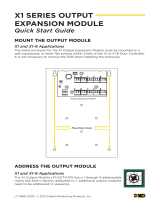
734 Installation and Programming Guide | Digital Monitoring Products 3
RED
PROG
RED
KYPD OUT
DATA
XMT LED
WIEGAND
READ LED
RELAY
ON
NC
C
NO
GRN
YEL
RED + –
Piezo
1234 5 6 7 810 11 12 13 14
9
LC ASREDWHTGRN BLK Z1 Z2 Z3 Z4+ Z4–RA GND GND
KYPD IN
RED
ON
1 2 3 4
Reader
Inputs
Status
Indicator
Outputs Zones
To Panel
Keypad Bus
or AX-Bus
Piezo
Address DIP
Switches
Door Relay
Terminal
Indicator
LEDs
Keypad
Programming
Header
To Other
Keypad Bus
or AX-Bus
Figure 1: 734 Layout
734 PCB FEATURES

734 Installation and Programming Guide | Digital Monitoring Products 4
INSTALL THE 734
1 Mount the 734
The module comes in a high-impact plastic housing that you can mount directly to a wall, backboard, or other flat
surface.
For easy installation, the back and ends of the 734 housing have wire entrances. The back also contains multiple
mounting holes that allow you to mount the module on a single-gang switch box. DMP recommends mounting the
734 near the protected door. Refer to Figure 2 for mounting hole locations on the housing base.
1. Remove the PCB from the plastic housing by loosening the clips
on one side and gently lifting it out of the housing base.
2. Insert the included screws in the desired mounting hole locations
and tighten them to secure the housing to the surface.
3. Reinstall the PCB in the housing base.
2 Wire the Access Control Lock
The 734 provides a Form C (SPDT) relay for controlling locks and other electronically-controlled barriers. The
three relay terminals marked NO C NC allow you to connect the device wiring to the relay for module control.
Use an additional power supply to power magnetic locks and door strikes. See Figure 3 and Figure 4 for typical
magnetic lock and door strike wiring.
The Form C relay draws up to 35mA of current and contacts are rated for 10Amps (resistive) at 12/24VDC.
When connecting multiple locks to the Form C relay, the total current for all locks cannot exceed 10Amps. If the
total current for all locks exceeds 10Amps, problems may arise and an isolation relay may be needed. Refer to
“Isolation Relay (optional)” for more information.
Figure 2: Mounting Hole Locations
Mounting Holes
Model 333
Suppressor
–+
12/24 VDC
Power Supply
Normally Closed
Magnetic Door
Lock
Mag lock positive
to Terminal NC
Power supply positive
to Terminal C
Mag lock negative to
power supply negative
Figure 3: Typical Magnetic Lock Wiring
Model 333
Suppressor
–+
12/24 VDC
Power Supply
Normally Open
Door strike positive
to Terminal NO
Power supply positive
to Terminal C
Door strike negative to
power supply negative
DC Door Strike
Figure 4: Typical Door Strike Wiring
Wire the 734
KYPD IN / KYPD OUT Connections
▶KYPD IN (Keypad In): Receives and transmits data to the panel Keypad bus/AX-Bus.
▶KYPD OUT (Keypad Out): Receives and transmits data out to other keypad(s) or module(s). Install a
dual-connector harness to allow connection to other devices up to the maximum number of devices
supported.
Caution: When the 734 is powered from 24VDC, do not connect devices to KYPD OUT header.
3

734 Installation and Programming Guide | Digital Monitoring Products 5
Isolation Relay (Optional)
The Form C relay can control a device that draws less than 10Amps of current. If a device draws more than
10Amps of current, or the sum of all devices controlled by the Form C relay exceeds 10Amps, an isolation relay
must be used. Refer to Figure 5 and Figure 6 for isolation relay wiring.
4
5Install the 333 Suppressor
Use the included 333 suppressor with the 734 to suppress any surges caused by energizing a magnetic lock or
door strike.
Install the 333 across the module’s C (common) and NO (normally open) or NC (normally closed) terminals.
If the device being controlled by the relay is connected to the NO and C terminals, install the suppressor on the
NO and C terminals.
Conversely, if the device is connected to the NC and C terminals, install the 333 Suppressor on NC and C
terminals.
The suppressor wire is non-polarized. Install the suppressor as shown in Figure 7.
Status LEDs
The 734 board contains three status LEDs.
▶The Red LED turns on for the same duration as the door strike relay.
▶The Yellow LED turns on for one second to indicate receipt of a valid input determined by card format
programming.
▶The Green LED indicates data sent to the panel.
Magnetic Lock
–+
Isolation Relay
NO C NC
To Panel
Keypad
Bus
Common
RED
PROG
PIEZO
RED KYPD IN RED KYPD OUT
RED
WIEGAND
READ LED
DATA
XMT LED
RELAY
ON
YEL GRN
Normally Open
12/24VDC
Power
Supply
734
Series
Module
Model 333
Suppressor
+
+
+
–
+–
Magnetic Lock
–+
Mag Lock
NO C NC
Normally Closed
+
–
Figure 5: Magnetic Lock with an Isolation Relay
Magnetic Lock
–+
Isolation Relay
NO C NC
To Panel
Keypad
Bus
Common
RED
PROG
PIEZO
RED KYPD IN RED KYPD OUT
RED
WIEGAND
READ LED
DATA
XMT LED
RELAY
ON
YEL GRN
Normally Open
Normally Open
12/24VDC
Power
Supply
734
Series
Module
Model 333
Suppressor
+
+
–
+
+
–
+–
Magnetic Lock
–+
DC Door Strike
NO C NC
Figure 6: Door Strike with an Isolation Relay
RED
PROG
PIEZO
RED KYPD IN RED KYPD OUT
RED
WIEGAND
READ LED
DATA
XMT LED
RELAY
ON
YEL GRN
734
Series
Module
Model 333
Suppr
essor
+–
NO CNC
Figure 7: 333 Suppressor Installation on the 734

734 Installation and Programming Guide | Digital Monitoring Products 6
6Wire the Zone Terminals
Terminals 8 through 12 connect grounded zones1 through 3. These zones have a grounded side and cannot be
used for fire-initiating devices. Zones 2 and 3 can also be used for access control with zone2 providing a bypass
feature and zone3 providing request to exit functionality.
Terminals 13 and 14 connect to zone4. Zone 4 provides a non-powered Class B ungrounded zone suitable for
connection to fire devices such as heat detectors or pull stations.
Note: You must provide a mechanical means of resetting four-wire smoke detectors or other latching
devices on zone4. The panel does not drop power to the Keypad Bus or AX-Bus when a Sensor Reset is
performed.
Use the supplied 311 1k Ohm End-of-Line (EOL) resistors on each zone. Refer to the panel programming guide for
programming instructions. See Table 1 and Figure 8 for more information on wiring the zone terminals.
ZONE # RECOMMENDED DEVICE RESIDENTIAL FIRE
DEVICE?
1 Any burglary device No
2 Door contact No
3 REX (PIR or Button) No
4 Any Device Yes
Table 1: 734 Zone Uses
Zone 1
Zone 2
Zone 3
Zone 4
1234 5 6 7 810 11 12 13 14
9
LC ASRED WHTGRN BLK Z1 Z2 Z3 Z4+ Z4–RA GND GND
1k Ω EOL
1k Ω EOL
1k Ω EOL
1k Ω EOL
Zone 3 can also
be wired normally
closed with an in‑line
1k Ohm resistor
Figure 8: Zone Terminal Wiring
7a Connect a Wiegand Card Reader
The 734 provides direct 12/24VDC output to the reader on the Red terminal connection. Figure 9 shows a
reader with wire colors RED, WHT, GRN, and BLK connecting to Terminals 1, 2, 3, and 4.
The green wire carries Data Zero (D0), and the white wire carries Data One (D1). The red wire connects
12/24VDC and the black wire is ground.
The wire colors may be dierent depending on the reader being installed. Refer to the literature provided with
the reader for wire coding, wire distance, cable type (such as shielded), and other specifications.
Wiegand Status Indicator Outputs
Terminals 5, 6, and 7 provide connections for Remote LED Control, Remote Annunciation, and Armed Status
indicators.

734 Installation and Programming Guide | Digital Monitoring Products 7
7b Connect an OSDP Card Reader
The 734 provides 12/24VDC to the reader on the RED terminal connection and two-way data transmission on
the GRN and WHT connection. Only one OSDP reader can be connected to a module.
Use 24 AWG or larger two conductor RS-485cable to connect a reader to module terminals. For data
transmission, connect the A (485 –) wire to the GRN terminal and the B (485 +) wire to the WHT terminal. For
reader power, connect the red (DC +) wire to the RED terminal and the black (DC –) wire to the BLK terminal.
Refer to Figure 10.
Wire colors may be dierent depending on the reader. Refer to literature provided with the reader for wire
coding, distance, and other specifications.
Note: OSDP card readers require 734 Access Control modules with PCB Rev 6 and higher.
LC (Remote LED Control)
Remote LED Control provides an unsupervised switched ground for a visual indicator that turns on when the
relay activates. Connect the wire from the LC Terminal to an LED. The LED turns on for the duration the door
strike relay is on. HID readers optionally provide a connection for LED reader control.
LC WIRE COLOR LED COLOR
Orange Green
Brown Red
RA (Remote Annunciation)
Remote Annunciation provides an unsupervised switched ground for a remote annunciator that turns on when
the Zone 2Bypass timer expires. Connect the wire from the RA Terminal to a remote annunciator. The remote
annunciator silences when the RA restores. The remote annunciator (RA) switched ground operates even if
the speaker is programmed not to operate.
AS (Armed Status)
Armed Status provides an unsupervised switched ground for a visual or audible armed status indicator that
turns on when the burglary areas are armed, such as SYSTEM ON or ALL SYSTEM ON. Connect a wire from
the AS Terminal to an armed status indicator.
Caution: Status indicator outputs support a maximum of 100mA per terminal. Exceeding the maximum
rating on LC, RA, or AS terminals can damage equipment.
Red (12/24VDC)
Black (GND)
Orange or Brown (LED)
Yellow (Buzzer)
Green (Data 0)
Typical
Wiegand
Card Reader
White (Data 1)
1234 5 6 7 810 11 12 13 14
9
LC ASRED WHT GRN BLK Z1 Z2 Z3 Z4+ Z4–RA GND GND
ON
1 2 3 4
Figure 9: Wiegand Card Reader Wiring

734 Installation and Programming Guide | Digital Monitoring Products 8
OSDP Reader LED Operation
OSDP readers connected to 734 modules provide visual indication of relay condition, connection type, and
encryption status with a red and green LED. Enable reader LED operation in LED CONTROL.
If enabled, the reader LED is turned on and operates the same as a Wiegand reader LED, lighting green when the
module relay activates. Visual indication for connection and encryption status functions as follows:
▶Fast blink (50 ms interval)—Connection secure, encrypted with 128-bitAES and your custom secure key.
▶Slow blink (100 ms interval)—Connection encrypted with the default SIA secure key.
The LED is not controlled by the device.
OSDP Reader Annunciation
OSDP readers connected to 734 modules provide audible indication of card reads. Enable reader annunciation in
BUZZER CONTROL.
If enabled, the reader’s internal annunciator follows normal RA terminal operation.
If disabled, the reader’s internal annunciator will beep once when a credential is presented.
OSDP Status Indicator Outputs
Terminals 6 and 7 provide connections for Remote Annunciation and Armed Status indicators.
RA (Remote Annunciation)
Remote Annunciation provides an unsupervised switched ground for a remote annunciator that turns on when
the Zone 2Bypass timer expires. Connect the wire from the RA Terminal to a remote annunciator. The remote
annunciator silences when the RA restores. The remote annunciator (RA) switched ground operates even if the
speaker is programmed not to operate.
AS (Armed Status)
Armed Status provides an unsupervised switched ground for a visual or audible armed status indicator that turns
on when the burglary areas are armed, such as SYSTEM ON or ALL SYSTEM ON. Connect a wire from the AS
Terminal to an armed status indicator.
Caution: Status indicator outputs support a maximum of 100mA per terminal. Exceeding the maximum
rating on LC, RA, or AS terminals can damage equipment.
1234 5 6 7 810 11 12 13 14
9
LC ASRED WHT GRN BLK Z1 Z2 Z3 Z4+ Z4–RA GND GND
A (485 –)
Black (GND)
OSDP Card
Reader
B (485 +)
Red (12/24 VDC)
ON
1 2 3 4
Figure 10: OSDP Card Reader Wiring

734 Installation and Programming Guide | Digital Monitoring Products 9
HID Signo OSDP Card Reader Wiring
When using OSDP mode on a HID Signo card reader, the typical wiring is switched. When using Wiegand mode,
the wiring will stay the same.
The HID Signo card reader should be wired as follows:
▶Red to Red
▶Green to White
▶White to Green
▶Black to Black
1234 5 6 7 810 11 12 13 14
9
LC ASRED WHT GRN BLK Z1 Z2 Z3 Z4+ Z4–RA GND GND
D1/DATA/485-A (WHITE)
BLACK (GND)
RED (12/24 VDC)
ON
1 2 3 4
Signo OSDP
Card Reader
D0/CLOCK/485-B (GREEN)
Figure 11: Signo OSDP Card Reader Wiring
8 Set the 734 Address
To set the 734 address, move the DIP switches on the PCB to the appropriate positions. See the following sections, Figure 11,
and Table 2 to determine how to set Keypad Bus or AX-Bus addresses.
Keypad Bus Addresses Explained
Each Keypad Bus address can accommodate one door output and four expansion zones. A 734 with an address of 2 on
the Keypad Bus would represent door2 and zones21-24. A 734 with a keypad address of 14 would represent door14 and
zones141-144.
AX‑Bus Addresses Explained
XR550 panels are capable of access control expansion using any of the five AX/LX-Bus headers (AX/LX500, 600,
700, 800, and 900). An AX-Bus address can accommodate one door output and one expansion zone. Because
the 734 has a built-in four-zone expander, three extra zones will be mapped to the 734 automatically.
A 734 with an address of 1 on AX500 would represent door501 and zones501-504. A 734 with an address of 2
on AX500 would represent door505 and zones505-508. A 734 with an address of 1 on AX700 would represent
door701 and zones701-704.
Note: Hardwired zone expanders and modules do not communicate on an AX-Bus. Doors connected to
the AX-Bus do not have programmable device or communication types and do not have assignable display
areas.

734 Installation and Programming Guide | Digital Monitoring Products 10
1 2 3 4
5 6 7 8
9 10 11 12
13 14 15 16
ON
1 2 3 4
ON
1 2 3 4
ON
1 2 3 4
ON
1 2 3 4
ON
1 2 3 4
ON
1 2 3 4
ON
1 2 3 4
ON
1 2 3 4
ON
1 2 3 4
ON
1 2 3 4
ON
1 2 3 4
ON
1 2 3 4
ON
1 2 3 4
ON
1 2 3 4
ON
1 2 3 4
ON
1 2 3 4
Figure 12: Keypad/AX Bus Addresses
734 Address Table
To set the module’s address, move the DIP switches to the appropriate positions. See Figure 11 for Keypad Bus
and AX-Bus DIP switch positions.
KEYPAD BUS AX-BUS
Device/
Door Zones Device/
Door Zones Device/
Door Zones Device/
Door Zones Device/
Door Zones Device/
Door Zones
1 11-14 501 501-504 601 601-604 701 701-704 801 801-804 901 901-904
2 21-24 505 505-508 605 605-608 705 705-708 805 805-808 905 905-908
3 31-34 509 509-512 609 609-612 709 709-712 809 809-812 909 909-912
4 41-44 513 513-516 613 613-616 713 713-716 813 813-816 913 913-916
5 51-54 517 517-520 617 617-620 717 717-720 817 817-820 917 917-920
6 61-64 521 521-524 621 621-624 721 721-724 821 821-824 921 921-924
771-74 525 525-528 625 625-628 725 725-728 825 825-828 925 925-928
8 81-84 529 529-532 629 629-632 729 729-732 829 829-832 929 929-932
9 91-94 533 533-536 633 633-636 733 733-736 833 833-836 933 933-936
10 101-104 537 537-540 637 637-640 737 737-740 837 837-840 937 937-940
11 111-114 541 541-544 641 641-644 741 741-744 841 841-844 941 941-944
12 121-124 545 545-548 645 645-648 745 745-748 845 845-848 945 945-948
13 131-134 549 549-552 649 649-652 749 749-752 849 849-852 949 949-952
14 141-144 553 553-556 653 653-656 753 753-756 853 853-856 953 953-956
15 151-154 557 557-560 657 657-660 757 757-760 857 857-860 957 957-960
16 161-164 561 561-564 661 661-664 761 761-764 861 861-864 961 961-964
Table 2: Device Addresses and 734 Zone Numbers

734 Installation and Programming Guide | Digital Monitoring Products 11
9Connect the Power Supply
Power for the 734 can be provided by a 12 or 24 VDC power supply. The 12 VDC power can be provided by the
panel keypad bus or from a separate power supply. The 24 VDC power supply can be connected directly to the
relay terminal block (J1).
Warning: To avoid the risk of equipment damage, do not exceed 750 mA total output current for zones
connected to the module.

734 Installation and Programming Guide | Digital Monitoring Products 12
PROGRAM THE PANEL
To access the Programmer menu, reset the panel, enter 6653 (PROG), then press CMD.
After completing each of the following steps, press CMD to advance to the next option. Refer to the panel
programming guide as needed.
DEVICE SETUP
Advance to DEVICE SETUP, then press a select area or top row key to enter the setup
menu.
Device Number
Set the module’s address. For information about valid addresses, refer to Table 2.
Device Name
Press any select area or top row key, then enter a name for the module.
Device Type
Press any select area or top row key, then select DOOR as the device type.
Communication Type
If the module is connected to the Keypad Bus, select KPD (Keypad Bus). If the
module is connected to the AX-Bus, select AX-BUS. Press any select area or top row
key to display available options.
Configure additional options as needed. To configure specific options for the module locally, do not program CARD
OPTIONS or 734 OPTIONS in Device Setup.
DEVICE SETUP
DEVICE SETUP
DEVICE NO: -
DEVICE SETUP
*UNUSED*
DEVICE SETUP
TYPE: DOOR
DEVICE SETUP
COMM TYPE: AX-BUS

734 Installation and Programming Guide | Digital Monitoring Products 13
PROGRAM THE 734
When you program a 734, you can use a keypad connected to the 734 programming header and set to address 1. For
12V applications, connect the keypad to the module using a Model 330 4-wire harness. For 24V applications, connect
the keypad to the module using a Model 330-24 4-wire programming harness with in-line resistor.
Caution: Do not connect a keypad using a standard Model 330 harness if using a 24V power supply! Damage to
the keypad could occur.
You can also program the 734 from an XR150/XR550 Series panel. If you choose to program the 734 from the panel,
all future programming should be performed through the panel. The panel’s programming overrides any programming
performed from a keypad connected to the 734. While the 734 is in programming mode, it will not be able to
communicate with the panel.
Caution: OSDP readers can only be programmed locally from the module with a keypad. To properly bond the
reader to the module, the 734 must be new or initialized and the reader must be new or factory reset. After
programming is complete and the keypad is disconnected, the reader is bonded to the module and cannot be
reprogrammed with a dierent secure key until it is factory reset by the manufacturer.
PROGRAMMER MENU
When you connect the keypad to the 734module, the version number and release
date display. Press CMD to advance to Initialization Options.
INITIALIZATION OPTIONS
These options can set the 734module’s programming memory back to factory
defaults. Press any select key or area to enter the Initialization Menu. Press CMD to
advance to “Access Options”.
Note: If programming an OSDP reader, the module must be initialized and the
reader must be new or set to factory defaults by the manufacturer.
Initialize Confirm Option: After selecting YES to clear the Access Options, the
734displays SURE? YES NO for confirmation to clear the memory. This is a
safeguard against accidentally erasing the programming. No memory is cleared from
the programming until you answer YES to the SURE? option. Selecting NO leaves
communication options unchanged.
ACCESS OPTIONS
Reader Protocol Type
Set the734to work with Wiegand or OSDP card readers. Press any top row key or
select area to change the module’s Reader Protocol Type. The default is WIEGAND.
If you choose Wiegand, the menu advances to “Activate Zone 2 Bypass”. If you
choose OSDP, the menu advances to OSDP LED Control.
OSDP LED Control
Select YES to enable reader LED operation. Select NO to disable reader LED
operation. For more information, refer to Connect an OSDP Card Reader.
OSDP Buzzer Control
Select YES to enable built-in reader annunciation. Select NO to disable built-in reader
annunciation. For more information, refer to Connect an OSDP Card Reader.
734 PROGRAMMING
VER VVV MM/DD/YY
INITIALIZE ALL?
NO YES
ARE YOU SURE?
YES NO
READER PROTOCOL
TYPE WIEGAND
READER PROTOCOL:
WIEGAND OSDP
LED CONTROL:
NO YES
BUZZER CONTROL:
NO YES

734 Installation and Programming Guide | Digital Monitoring Products 14
OSDP Secure Key
The secure key is programmed into the OSDP reader and is used to establish128-bit
AES encrypted two-way communication between the reader and module.
Record this key and store it in a secure location away from the module and reader.
After the reader is bonded to the module, the secure key cannot be changed in the
reader or retrieved from 734 programming. Replacement modules can be bonded to
any compatible reader with the reader’s secure key.
Caution: OSDP readers can only be programmed locally from the module with a
keypad. To properly bond the reader to the module, the 734 must be initialized
and the reader must be new or factory reset. After programming is complete
and the keypad is disconnected, the reader is bonded to the module and cannot
be reprogrammed with a dierent secure key until it is factory reset by the
manufacturer.
Enter a secure key up to16alphanumeric characters. These characters are visible until
CMD is pressed.
Activate Zone 2 Bypass
Select YES to activate the zone2 bypass operation. Selecting NO allows standard
zone operation on zone2. The default is NO.
If the door being released by the 734 module is protected (contact installed), a
programmable bypass entry/exit timer can be provided by connecting its contact
wiring to module zone2. When the onboard Form C relay activates and the user
opens the door connected to zone2, the zone is delayed for the number of seconds
programmed in ZONE 2 BYPASS TIME allowing the user to enter/exit during an armed
period.
If zone2 does not restore (door closed) within the programmed time, the piezo
sounds every other second during the last ten seconds. If zone2 restores prior to the
end of the programmed time, the piezo silences. If the zone does not restore before
the programmed time, the 734 ends the bypass and indicates the open or short zone
condition to the panel.
Zone 2 Bypass Time
Enter the number of seconds to elapse before the bypass timer expires. The range
is 20-250 seconds. Press any select key or area to enter the number of seconds. The
default is 40seconds. Figure 12 shows how the bypass option works.
SECURE KEY
SECURE KEY
****************
ACTIVATE ZONE2
BYPASS? NO YES
ZONE2 BYPASS
TIME: 40
5-Second
Strike
40-Second Zone 2
Bypass Entry/Exit Timer
10 seconds before
the bypass time expires,
the device beeps if
the door is still open.
End of
Timer
40
Seconds
A zone open/short is
indicated if the door
remains open.
Figure 13: Zone 2 Bypass Timeline

734 Installation and Programming Guide | Digital Monitoring Products 15
Relock on Zone 2 Changes
Selecting YES turns the relay o when zone2 changes state. Selecting NO leaves the
relay on when zone2 changes state. Turning o the relay allows a long strike time to
be automatically ended upon zone 2 change and relocks the door. The default is NO.
Activate Zone 3 Request to Exit
Selecting YES activates the zone3 Request to Exit (REX) option. Selecting NO allows
standard zone operation on zone3. Default setting is NO.
Connect a motion sensing device or a mechanical switch to zone3 to provide REX
capability to the system. Zone 3 can be used to activate the strike relay and bypass or
activate bypass only. For zone wiring details, refer to Figure 8.
Activate Strike Relay and Bypass
Wire zone 3 as normally open with a 1k Ohm EOL resistor.
When zone3 shorts, the onboard Form C relay activates for the programmed number
of seconds. See “Zone 3 REX Strike Time”. During this time, the user can open the
protected door to start the programmed zone2 bypass entry/exit timer. After the
programmed number of seconds, the relay restores the door to its locked state.
Activate Bypass Only
Wire zone 3 as normally closed with an in-line 1k Ohm resistor.
When zone3 opens from a normal state, only a bypass occurs and the onboard relay
does not activate.
Zone 3 REX Strike Time
Enter the number of REX seconds to elapse. The range is5to 250 seconds. Press any
select key or area to enter the number of seconds. The default is 5 seconds.
Activate Onboard Speaker
Select YES to enable the onboard piezo for local annunciation, such as alarm and
trouble annunciations. Select NO to turn the speaker o for all operations. This does
not aect remote annunciator open collector (RA) operation. The default is NO.
Card Formats
Select DMP to allow credentials that use a 26 - 45bit data string. The menu advances
to “Require Site Code”.
Select CUSTOM to disable DMP format and program slots 1-8 as needed. The menu
advances to “Card Format Number”.
Select ANY to allow all card reads to activate the door strike relay. The door strike
relay is activated for the length of time programmed in ZN3 REX TIME. No user code
information is sent to the panel. The menu advances to “No Communication with
Panel”.
The default card format is DMP.
RELOCK ON ZONE2
CHANGE? NO YES
ACTIVATE ZONE3
REX? NO YES
ZN 3 REX STRIKE
TIME: 5
ACTIVATE ONBOARD
SPEAKER? NO YES
CARD FORMATS
DMP CUSTOM ANY

734 Installation and Programming Guide | Digital Monitoring Products 16
Card Format Number
Notice: If you see CARD OPTIONS, refer to LT‑0737C.
Select the slot number (1-8) that you want to program for a custom non-DMP card
format. The format that is programmed into slot 1 is the default format. In the event
that a card with an unrecognized format is used, that card will be read in the format
that is programmed in slot 1. To restrict card reads to specific formats, only program
slots 2-8.
See “Public Card Formats” for some publicly available card formats that can be
used with the 734. Other private or custom formats may also be compatible. Please
contact the credential supplier or manufacturer for the bit structure.
Note: If you select slot 1 and you are upgrading from XRpanel version 182 or
earlier, FORMAT NAME will automatically be named SINGLE CARD FORMAT and
WIEGAND CODE LENGTH will default to 45.
Format Name
Press any select area to rename the card format. Press CMD to save and advance.
Wiegand Code Length
When using a custom credential, enter the total number of bits to be received in
Wiegand code including parity bits.
Press any select key or area to enter a number between 1-255to equal the number of
bits. Default is 26bits.
An access card contains data bits for a site code, user code, and start/stop/parity bits.
The starting position, location, and code length must be determined and programmed
into the keypad. See Figure 13.
Site Code Position and Length
Enter the site code start position and length in the data string. Press select area 2 to
clear the site code start position and enter a number between 0-255. Press CMD to
save. Default is 1.
Press select area 4 to clear the site code length and enter a number between 1-24.
Press CMD to save. Default is 8.
CARD FORMATS
FORMAT NO: -
FORMAT NAME
*UNUSED*
WIEGAND CODE
LENGTH: 26
SITE CODE
POS: 1 LEN: 8
01110101101101010001100111
First Bit
Received
Position = 0
Site Code
Position = 1
Length = 8
User Code
Position = 9
Length = 16
Last Bit
Received
Position = 25
Example: Wiegand Code Length = 26 bits
Figure 14: Wiegand Data Stream Bit Location

734 Installation and Programming Guide | Digital Monitoring Products 17
User Code Position and Length
Define the user code start bit position and length. Press select area 2 to clear the user
code position and enter a number between 0-255. Press CMD to save. Default is 9.
Press select area 4 to clear the user code length and enter a number between 16-64.
Press CMD to save. Default is 16.
Require Site Code
Press the top row select key or area under YES to use a site code and press CMD to
view the site code entry display. Press NO to advance to NO OF USER CODE DIGITS.
Default is NO.
In addition to user code verification, door access is only granted when any one site
code programmed at the SITE CODE ENTRY option matches the site code received in
the Wiegand string.
Site Code Display: You can program up to eight 8-digit site codes. The site code
range is 0-16,777,214.
In the keypad display, enter site code 1 and press CMD. The display will ask for site
code 2 followed by site code 3 and so on. When you have selected the site code you
want to change, press CMD.
Number of User Code Digits
The 734 module recognizes user codes from 4-12digits long. Press any top row select
key or area to enter a user code digit length. This number must match the user code
number length being programmed in the panel. The device will recommend a number
of user code digits based on the user code length. Default is 5.
All bits are read and converted into a decimal number string. The number string is left
padded with 0 (zero) if needed for long user code lengths.
Example: # decoded 1234567
10 digits 0001234567
4 digits 4567
Card Format Added/Changed (Custom Format)
When a custom card format is added successfully, the keypad displays xx BIT ADDED,
where xx is the Wiegand code length. When the format is changed, the keypad
displays xx BIT Changed. Press CMD. The menu returns to “Card Format Number”.
Program another custom card format or press CMD to advance to NO COMM WITH
PNL.
USER CODE
POS: 9 LEN: 16
REQUIRE SITE
CODE: NO YES
SITE CODE 1:
NO OF USER CODE
DIGITS: 5
CARD FORMATS
26 BIT ADDED
Site Code
You can program up to eight three-digit site codes. The site code
range is 0-999. Any previously programmed site codes display.
Dashes represent blank site codes and indicate where digits display
on the keypad. The default for site code 1 is 127 for DMP.
Press the first select key or area to display the > character next to
site code 1. Press the first select key or area again to move vertically
between site codes. Press the second select key or area to move
horizontally between site codes. When you have selected the site
code you want to change, press CMD.
Enter Site Code
Press the first select key or area to enter a site code number. Enter
your three-digit site code and press CMD to advance.
Note: A card with a site code greater than three digits cannot be
used. Use only cards with three-digit site codes.
Press the fourth select key or area to delete the site code number
displayed and return to the site code display. Repeat these steps to
change, delete, or add other site codes.

734 Installation and Programming Guide | Digital Monitoring Products 18
No Communication with Panel
Define the relay action when communication with the panel has not occurred for
5seconds: OFF, SITE, ANY, ON, or LAST. Default is OFF. Press any select key or area
to change the default relay action:
Press the first select key or area to choose OFF (Relay Always O). The relay does
not turn on when any Wiegand string is received. OFF does not aect any REX
operation. If communication is lost during a door strike, the relay remains on for the
door strike duration but turns o at the end of the door strike timer.
Press the second select key or area to choose SITE (Accept Site Code). Door access
is granted when the Wiegand site code string received matches any site code
programmed at Site Code. Refer to “Require Site Code” for more information.
Press the third select key or area to choose ANY (Any Wiegand Read). Access is
granted when any Wiegand string is received.
Press the fourth select key or area to choose ON (Relay Always On). The relay is
always on.
Press CMD to display additional actions. Press the first select key or area to choose
LAST (Keep Last State). The relay remains in the same state and does not change
when communication is lost.
REMOVE KEYPAD
After programming is saved, the REMOVE KEYPAD option continually displays with
no timeout if the keypad remains connected to the module. After five seconds, the
piezo begins sounding continually. To disconnect the keypad and silence the piezo,
remove the keypad harness.
NO COMM WITH PNL
OFF
OFF SITE ANY ON
OFF SITE ANY ON
OFF SITE ANY ON
OFF SITE ANY ON
LAST
REMOVE KEYPAD
/