Page is loading ...

INSTALLATION AND PROGRAMMING GUIDE
714N-POE Network
Zone Expander Module


Table of Contents .......................................a
About the 714N-POE .................................. 1
Power Supply ......................................................... 1
Zone Terminals ...................................................... 1
Programming Connection ................................. 1
PCB Features ...............................................2
Install the 714N-POE Module .................... 3
Mount the Device ................................................ 3
Network Connection .......................................... 4
Wire the Zone Terminals ................................... 5
Addressing the 714N-POE ............................... 6
Program the 714N-POE Module ...............8
Program Start Display ....................................... 9
Initialization Option ............................................ 9
Initialize Confirm Option .................................. 9
Communication Menu ........................................ 9
TABLE OF CONTENTS
714N DHCP ............................................................10
714N IP Address ..................................................10
Subnet Mask .........................................................10
Gateway Address ...............................................10
Panel IP Address .................................................10
Panel IP Port .......................................................... 11
714N-POE Passphrase .......................................11
714N-POE Network Specifications ........ 12
Compliance Listing Specifications ........ 13
Certifications ............................................. 14
Underwriters Laboratory (UL Listed) .........14
Product Specifications ............................ 15

Digital Monitoring Products, Inc. | 714N-POE Installation and Programming Guide 1
PROGRAMMING CONNECTION
The module also provides a keypad programming
connection for use with a standard DMP LCD
keypad for initial setup. Programming can be
completed using a keypad connected to the
module or from XR150/XR550 panels.
The 714N-POE Network Zone Expander Module allow you to add 4 zones to XR150/XR550 Series
panels using IP network capability. The 714N-POE is compatible with 1k to 10k resistors, giving a wide
variety of options for takeovers.
POWER SUPPLY
714N-POE module operates at 12 VDC from
a power supply. The 714N-POE can also be
powered from POE.
ZONE TERMINALS
Four input zones are provided to allow
connection of nearby burglary devices.
ABOUT THE 714N-POE

2 714N-POE Installation and Programming Guide | Digital Monitoring Products, Inc.
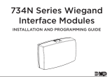
PCB FEATURES
DC INPUT
ZONES
INDICATOR
LEDS
Figure 1: PCB Features
POWER OUTPUT

Digital Monitoring Products, Inc. | 714N-POE Installation and Programming Guide 3
INSTALL THE 714N-POE MODULE
The module comes in a high-impact plastic housing that you can mount directly to a wall, backboard,
or other flat surface.
For easy installation, the back and ends of the housing have wire entrances. The back also contains
multiple mounting holes that allow you to mount the module on a single-gang switch box.
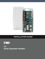
1. Remove the circuit board from the plastic housing by loosening the clips on one side and gently
lifting it out of the housing base.
2. Use the included screws in the desired mounting hole locations to attach the remote module to
the surface. See the shaded mounting hole locations in Figure 2.
3. Reinstall the circuit board in the housing base.
MOUNT THE DEVICE
Mounting Hole
Figure 2: Mounting Hole Locations

4 714N-POE Installation and Programming Guide | Digital Monitoring Products, Inc.
Connect an IP network cable from the LAN/WAN connection to the 714N-POE Network connector.
The 714N-POE module communicates AES encrypted TCP with panels that have network installed.
Two LED’s are located on the ethernet jack.
• The green LED indicates data sent to the panel.
• The yellow LED indicates the speed of the transmission. A solid yellow LED indicates
the network is connected at 100 Base-T. A flashing yellow LED indicates the network is
connected at 10 Base-T.
NETWORK CONNECTION

Digital Monitoring Products, Inc. | 714N-POE Installation and Programming Guide 5
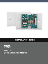
WIRE THE ZONE TERMINALS
Terminals 5-9 connect grounded zones 1 through 3. Zone 4 terminals provide a non-powered Class
B, Style A zone. The valid range of EOL resistors is 1k to 10k, allowing for a wider range of takeovers.
Refer to the panel programming guide for programming instructions. See Figure 2 for more
information on wiring the zone terminals.
Figure 2: Zone Terminal Wiring
Zone 1
Zone 2
Zone 3
Zone 4
EOL
EOL
EOL
EOL
1
2
3
4 5 6 7
8
10
11
9

6 714N-POE Installation and Programming Guide | Digital Monitoring Products, Inc.
ADDRESSING THE 714N-POE
Note: For XR Series Version 192 firmware and lower, the 714N-POE must be programmed as a
network door. In Version 193 firmware and higher, the 714N-POE should be programmed as a
network expander. Refer to the XR Series panel programming guide (LT-1232) as needed.
Keypad Bus Addresses
DMP XR150/XR550 Series panels use keypad bus addresses 1 through 16. Each keypad bus address
can accommodate one 714N-POE. A module with an address of 2 on the keypad bus would represent
Door 2 and zones 21-24. A module with a keypad address of 14 would represent Door 14 and zones
141-144.
AX-Bus Addresses (XR550 only)
DMP XR550 panels are capable of access control expansion using any of the five AX/LX-Bus headers
(AX/LX500, 600, 700, 800, and 900). The 714N-POE takes up an AX-Bus address that can no longer
be used for a door. The 714N-POE module shares AX-bus addresses with the 734N, which limits the
number of devices to 16. A module with an address of 501 on AX500 would represent zones 501-504.
A module with an address of 505 on AX500 would represent zones 505-508. A module with an
address of 701 on AX700 would represent zones 701-704.

Digital Monitoring Products, Inc. | 714N-POE Installation and Programming Guide 7
Setting the 714N-POE Addresses
Only valid zone numbers can be assigned 714N-POE in device setup. For complete keypad and AX-
Bus address mapping, see the chart below.
Table 1: Device Addresses and 714N-POE
Zone Numbers
DEVICE ZONES DEVICE ZONES DEVICE ZONES DEVICE ZONES DEVICE ZONES DEVICE ZONES
1 11-14 501 501-504 601 601-604 701 701-704 801 801-804 901 901-904
2 21-24 505 505-508 605 605-608 705 705-708 805 805-808 905 905-908
3 31-34 509 509-512 609 609-612 709 709-712 809 809-812 909 909-912
4 41-44 513 513-516 613 613-616 713 713-716 813 813-816 913 913-916
5 51-54 517 517-520 617 617-620 717 717-720 817 817-820 917 917-920
6 61-64 521 521-524 621 621-624 721 721-724 821 821-824 921 921-924
7 7 1-74 525 525-528 625 625-628 725 725-728 825 825-828 925 925-928
8 81-84 529 529-532 629 629-632 729 729-732 829 829-832 929 929-932
9 91-94 533 533-536 633 633-636 733 733-736 833 833-836 933 933-936
10 101-104 537 537-540 637 637-640 737 737-740 837 837-840 937 937-940
11 111-114 541 541-544 641 641-644 741 741-744 841 841-844 941 941-944
12 121-124 545 545-548 645 645-648 745 745-748 845 845-848 945 945-948
13 131-134 549 549-552 649 649-652 749 749-752 849 849-852 949 949-952
14 141-144 553 553-556 653 653-656 753 753-756 853 853-856 953 953-956
15 151-154 557 557-560 657 657-660 757 757-760 857 857-860 957 957-960
16 161-164 561 561-564 661 661-664 761 761-764 861 861-864 961 961-964

8 714N-POE Installation and Programming Guide | Digital Monitoring Products, Inc.
PROGRAM THE 714N-POE MODULE
When you program the 714N-POE module, you must use a keypad connected to the programming
header and set to address 1.
You can also program the module from an XR150/XR550 Series panel. Initial programming of
device and communication must be performed with a keypad. Afterwards, device programming
and 714N-POE options may be programmed from the panel’s programming interface. The panel’s
programming overrides any programming performed from a keypad connected to the module.
RESET HEADER
To reset the module when first installing the system, short the two pins on the reset header before
applying power to the module.
To reset the module while the system is operational, short the two pins on the reset header for one or
two seconds without powering down the system.

Digital Monitoring Products, Inc. | 714N-POE Installation and Programming Guide 9
PROGRAM START DISPLAY
When you connect the keypad to the module, the version number
and release date display. Press 6653 (PROG) then CMD to enter the
Programming Menu.
INITIALIZATION OPTION
These options can set the 714N-POE module programming memory
back to factory defaults. Press any select key or area to enter the
initialization menu.
INITIALIZE CONFIRM OPTION
The module displays SURE? YES NO for confirmation to clear
the memory. This is a safeguard against accidentally erasing the
programming. No memory is cleared from the programming until you
answer YES to the SURE? option. Selecting NO leaves communication
options unchanged.
COMMUNICATION MENU
Press any select key or area to enter the Communication menu. Select
NET as the communication type.
714N PROGRAMMING
VER VVV MM/DD/YY
INITIALIZE ALL?
NO YES
ARE YOU SURE?
YES NO
714N
COMMUNICATION

10 714N-POE Installation and Programming Guide | Digital Monitoring Products, Inc.
714N DHCP
Select YES to use dynamic IP address information for the module’s
IP Address, Subnet Mask, and Gateway Address. Select NO to enter
static IP information.
714N IP ADDRESS
Enter the static IP address of the module if the DHCP is set to NO.
Default is 192.168.0.201.
SUBNET MASK
Enter the local subnet mask assigned to the module. Default is
255.255.255.0.
GATEWAY ADDRESS
Enter the local gateway address of the module. Default is 192.168.0.1.
PANEL IP ADDRESS
Enter the IP address of the panel. Default is 192.168.0.1.
Note: This IP address must match the address programmed in
the panel at the Local IP Address option in Network Options.
The DHCP programming in the panel must be set to NO.
714N
DHCP? NO YES
714N IP ADDRESS
192.168.0.201
SUBNET MASK
255.255.255.0
GATEWAY ADDRESS
192.168.0.1
PANEL IP ADDR
192.168.0.1

Digital Monitoring Products, Inc. | 714N-POE Installation and Programming Guide 11
PANEL IP PORT
Enter the port number that the module uses to send communication
to the panel. This must be the same port that is programmed in
the 714N-POE Listen Port in Network Options programming of the
panel. The panel IP port cannot be the same as the panel network
programming port. Default is 2002.
714N-POE PASSPHRASE
You must enter an 8-16 character alphanumeric passphrase to encrypt
communication with the panel. The passphrase for the 714N-POE
must match the 734N passphrase entered in Network Options
programming of the panel. If no 734N has been installed, a passphrase
is still required for the 714N-POE to communicate with the panel. The
passphrase is blank by default.
PANEL IP PORT
2002
734N
PASSPHRASE

12 714N-POE Installation and Programming Guide | Digital Monitoring Products, Inc.
The 714N-POE was designed to have minimum impact on network performance.
• If required, all of the trac between the 714N-POE(s) and the panel can be completely
isolated from the rest of the existing network by connecting all of the 714N-POE modules
and the panel to the same switch, then connecting the switch to the remainder of the
network. All trac between the 714N-POE and the panel would then be confined to the
switch where they are connected, while still allowing the panel to communicate with the
central station through the normal network.
• The 714N-POE is a single purpose network device. The module establishes outbound panel
communication using the TCP/IP protocol that remains open indefinitely. No inbound
communication is allowed. This prevents a potential intruder from making any type of
connection with the 714N-POE through the network.
• All communication between the 714N-POE and the control panel is encrypted using
128-bit AES encryption. This is the same encryption standard approved and used by the U.S.
government, including the National Security Agency for encrypting secret information.
• The socket can be closed by the 714N-POE or panel after a time-out.
• The connection is re-established by the 714N-POE after the time-out.
• A pair of supervision packets are sent every 5 seconds.
- The payload for each packet is 18 bytes and the total trac, including overhead, is
approximately 2 kilobytes per minute for each 714N-POE.
- Non-Supervision messages have a payload range of 18-50 bytes.
714N-POE encryption has not been evaluated by UL.
714N-POE NETWORK SPECIFICATIONS

Digital Monitoring Products, Inc. | 714N-POE Installation and Programming Guide 13
COMPLIANCE LISTING SPECIFICATIONS
COMMERCIAL BURGLARY (XR550 SERIES PANELS)
When using the zones of the 714N-POE in a listed application, place the module in a listed enclosure
and connect a DMP Model 307 Clip-on Tamper Switch to the enclosure programmed as a 24-Hour
zone. The 714N-POE zones can be used in a Low Risk application.

14 714N-POE Installation and Programming Guide | Digital Monitoring Products, Inc.
FCC Part 15
UNDERWRITERS LABORATORY (UL LISTED)
714N-POE
ANSI/UL 294 Access Control System Units
ANSI/UL 609 Local Burglar Alarm Units And Systems
ANSI/UL 1076 Proprietary Burglar Alarm Units And Systems
ANSI/UL 1610 Central Station Burglar-Alarm Units
CERTIFICATIONS

Digital Monitoring Products, Inc. | 714N-POE Installation and Programming Guide 15
PRODUCT SPECIFICATIONS
Primary Power 8.5 VDC to 28.5 VDC if 12 VDC
Current Draw
Standby/Alarm 75 mA at 12 VDC
When powered from POE
Standby/Alarm 25 mA
Output Voltage (POE) 12 VDC
Maximum Power Draw (POE) 12.95 W
Available Output Current 750 mA
Zones 5 VDC, 2 mA max
Dimensions 4.5W x 2.75H x 1.75D in
11.43W x 7H x 4.45D cm
Weight 8 oz .23 kg

16 714N-POE Installation and Programming Guide | Digital Monitoring Products, Inc.

LT-1947 19345 1.01 © 2019 Digital Monitoring Products, Inc.
/