Installation and user guide
MULTICAL® 303
Kmsrup A/S · Industrivej 28, Stilling · DK-8660 Skanderborg · T: +45 89 93 10 00 · [email protected] · kamstrup.com

2 Kamstrup A/S • 55122726_A2_GB_08.2021
MULTICAL® 303
Informion
Permissible opering condiions/mesuring rnges
Heat meter with approval according to MID and EN1434:
Temperature range q: 2 °C…180 °C DΘ: 3 K…178 K
Flow sensor (media temperature) qq: 2 °C…130 °C (MULTICAL® 303-W)
Cooling meter with approval according to DK-BEK 1178 and EN1434:
Temperature range q: 2 °C…180 °C DΘ: 3 K…178 K
Flow sensor (media temperature) qq: 2 °C…130 °C (MULTICAL® 303-T)/
qq: 2 °C…50 °C (MULTICAL® 303-C)
MID designion
Mechnicl environmen
Classes M1 and M2.
Elecromgneic environmen
Class E1 (housing/light industry). The meter’s signal cables must be drawn at a distance of
minimum 25 cm to other installations.
Climic environmen
Non-condensing, closed locations (indoors), ambient temperature of 5…55 °C
Minennce nd repir
The flow sensor and the temperature sensors must not be separated from the calculator. Repairs
require subsequent reverification in an accredited laboratory.

3Kamstrup A/S • 55122726_A2_GB_08.2021
MULTICAL® 303
Conens
1 In generl 4
2 Mouning of emperure sensors 5
2.1 Direct short sensor (DS) 5
2.2 Ø5.0 mm / Ø5.2 mm temperature sensors 6
2.3 Installation of Ø5.0 mm / Ø5.2 mm temperature sensors as direct temperature sensors 6
2.4 Sensor compatibility with flow sensors 7
3 Mouning of flow sensor 8
3.1 Mounting of couplings and direct short sensor in flow sensor 8
3.3 Mounting of MULTICAL® 303 flow sensor 9
3.2 Flow sensor position 9
3.4 Installation examples 10
3.5 Humidity and condensation 10
4 Mouning he clculor 11
4.1 Compact mounting 11
4.2 Wall-mounting 11
4.3 Positioning the calculator 12
5 Informion codes “INFO” 13
6 Volge supply 14
6.1 Battery supply 14
8 Communicion 14
8.1 M-Bus 14
8.2 Wireless M-Bus 14
7 Tesing of funcion 14
9 Seup 15
9.1 Changing the installation position 17

4 Kamstrup A/S • 55122726_A2_GB_08.2021
MULTICAL® 303
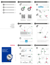
1 In generl
' Red his guide before you sr mouning he energy meer.
In cse of incorrec mouning, Kmsrup's gurnee obligions no longer pply.
Only use clen wer on dmp cloh o clen he meer.
Please note that the following installation conditions must be observed:
- Pressure stage: PN16/PN25, PS25, see marking.
At media temperatures above 90 °C, wall-mounting of the calculator is recommended.
At media temperatures below the ambient temperature, MULTICAL® 303 must be wall-mounted.

5Kamstrup A/S • 55122726_A2_GB_08.2021
MULTICAL® 303
2 Mouning of emperure sensors
The temperature sensors used for measuring inlet and outlet temperatures, respectively,
constitute a matched sensor set, which must never be separated. According to EN 1434/OIML R75,
the cable length must not be changed. Should replacement be necessary, both sensors must be
replaced.
The sensor marked with one line and the text t1 is to be installed in the inlet pipe. The other
sensor, marked with two lines and the text t2, is to be installed in the outlet pipe. This applies to
both heat installations, cooling installations and bi-functional heat- and cooling installations.
Depending on the installation type the sensors will also be marked red and blue to indicate the
correct installation position. However, the lines and the text t1 or t2 will always indicate the correct
installation position.
Noe The sensor cables must neither be exposed to jerking nor pulling. Please be aware of this
when binding the cables, and be careful not to pull the binders unnecessarily tight as this
may damage the cables. Please also note that temperature sensors must be mounted from
below in cooling and heat/cooling installations.
2.1 Direc shor sensor (DS)
The direct short sensors up to DN25 can be mounted in special ball valves with built-in M 10 socket
for the direct short sensor. They can also be mounted in installations with standard tee-pieces.
Kamstrup A/S can supply R½ and R¾ brass nipples that fit the direct short sensors. The direct
short sensor can also be mounted directly in selected flow sensors from Kamstrup A/S. Fasten the
sensors’ brass unions lightly (approx. 4 Nm) using a 12 mm face wrench, and seal the sensors with
seal and locking wire.

6 Kamstrup A/S • 55122726_A2_GB_08.2021
MULTICAL® 303
2.2 Ø5.0 mm / Ø5.2 mm emperure sensors
Both Ø5.0 mm and Ø5.2 mm temperature
sensors are delivered with mounted composite
unions and this is why they by default must
be used as direct temperature sensor. The
composite unions can be removed (see
Figure 1) after which the temperature sensors
can be used for installation in pockets. The
temperature sensors are made from rustproof
steel and have diameters of Ø5.0 mm or Ø5.2
mm. The temperature sensors are approved for
both PN16 and PN25 installations, with PS25
as the maximum pressure. The temperature
sensors are based on a 2-wire silicone cable
and can thus be used at media temperatures
up to 150 °C.
47.8
29.4 18.4
Ø5.0
Ø5.2 O-ring M10
Figure 1
This also applies to the composite union that is made from the material PPS. One of the
temperature sensors is mounted in the flow sensor on delivery and thus, only the other
temperature sensor must be mounted.
2.3 Insllion of Ø5.0 mm / Ø5.2 mm emperure sensors s direc emperure sensors
0
9 - 0.1
5.8 ±0.1
Figure 2 Measurement and tolerance requirements at installation of direct Ø5.0 mm or Ø5.2 mm temperature
sensor.
No matter where the direct Ø5.0 mm or Ø5.2 mm temperature sensor is installed, it is very
important to observe the tolerances stated in Figure 2. If not, the O-ring may not provide correct
sealing. To avoid damaging the O-ring at installation, it is important to use the provided guide when
installing Ø5.0 mm or Ø5.2 mm temperature sensors as direct temperature sensors.

7Kamstrup A/S • 55122726_A2_GB_08.2021
MULTICAL® 303
O-ring
O-ring
The O-ring guide is used for pushing the O-ring into place after which the temperature sensor can
be pushed to the bottom.
The composite union is tightened by hand. Do not use any tools.
2.4 Sensor compibiliy wih flow sensors
One of the two temperature sensors is always mounted in the flow sensor on delivery, but can
be mounted in a ball valve if required. Remember to mount a blind plug in the flow sensor if the
temperature sensor is moved and installed at another location.
Flow sensor Temperure sensor
Can be mounted in flow
sensor
qp DN G DS 27.5 Ø5.0 mm/
Ø5.2 mm
0.6-1.5 15 G¾B X X
1.5-2.5 20 G1B X X

8 Kamstrup A/S • 55122726_A2_GB_08.2021
MULTICAL® 303
3 Mouning of flow sensor
Prior to installation of the flow sensor, the system should be flushed and protection plugs/plastic
diaphragms removed from the flow sensor.
Correct position of the flow sensor appears either from the calculator’s type label or from the
display where ( indicates the position in inlet, whereas ) indicates the position in outlet. The
flow direction is symbolised by an arrow on the flow sensor.
3.1 Mouning of couplings nd direc shor sensor in flow sensor
The flow sensor can be used in connection with
either PN16 or PN25 (see marking).
Any provided blind plug, extension and gland
can be used with both PN16 and PN25.
In connecion wih flow sensors wih he
nominl dimensions G¾Bx110 mm nd
G1Bx110 mm, i mus be checked if he hred
run-ou is sufficien.
Couplings and gaskets are mounted as shown
in the figure. Make sure to position the gasket
correctly in the recess of the gland as shown in
the details excerpt in the figure.
Gasket
Torque ~4 Nm
Gasket
Kamstrup flow sensors require neither straight inlet nor straight outlet to meet the Measuring
Instruments Directive (MID) 2014/32/EU, OIML R75:2002 and EN 1434:2015. A straight inlet section
will only be necessary in case of heavy flow disturbances before the meter. It is recommended to
follow the guidelines of CEN CR 13582.

9Kamstrup A/S • 55122726_A2_GB_08.2021
MULTICAL® 303
3.2 Flow sensor posiion
A Recommended position.
B Recommended position.
C Unacceptable position due to risk of air
build-up.
D Acceptable position in closed systems.
E Ought not to be placed immediately after
a valve, with the exception of block valves
(ball valve type) which must be fully open
when not used for blocking.
F Ought not to be placed immediately before
or after a pump.
G Ought not to be placed immediately after a
double bend in two planes.
A
BC
D
E
FG
In order to avoid cavitation, the back pressure at the flow sensor (the pressure at the flow sensor
outlet) must be minimum 1.5 bar at qp (nominal flow) and minimum 2.5 bar at qs (maximum flow).
This applies to temperatures up to approx. 80 °C. The flow sensor must not be exposed to pressure
lower than the ambient pressure (vacuum).
3.3 Mouning of MULTICAL® 303 flow sensor
90°
90°
90°
90°
The flow sensor can be mounted horizontally, vertically or at an angle.

10 Kamstrup A/S • 55122726_A2_GB_08.2021
MULTICAL® 303
3.3.1 Threded meers 0.6...2.5 m3/h
0°0°
-45°-45°
1
The flow sensor can be mounted at 0° and may be turned downwards to 90°.
3.4 Insllion exmples
Threded meer:
Flow from left Flow from right
3.5 Humidiy nd condension
At the risk of condensation, e.g. in cooling installations, MULTICAL® 303 must be used in a
condensation-proof variant, type 303-C. At bifunctional heat/cooling energy measurements, type
303-T is used.

11Kamstrup A/S • 55122726_A2_GB_08.2021
MULTICAL® 303
4 Mouning he clculor
The MULTICAL® 303 calculator can be mounted in several ways either directly on the flow sensor
(compact mounting) or on a wall (wall-mounting).
4.1 Compc mouning
At compact mounting, the calculator is mounted directly
on the flow sensor. If there is a risk of condensation (e.g. in
cooling applications), the calculator must be wall-mounted.
Furthermore, MULTICAL® 303 in cooling applications must be the
condensation-proof version, type 303-C. In case of bifunctional
heat/cooling energy measurements, type 303-T is used.
MULTICAL® 303 is constructed in such a way that you always
obtain minimal mounting depth at compact mounting. The
design ensures that the mounting radius in critical places
remains 60 mm, both at 45° and 90° mounting of the flow
sensor.
90°
R60
45°
4.2 Wll-mouning
MULTICAL® 303 can be mounted directly on a plane wall. Wall-
mounting requires the use of a wall bracket (3026-655) that is
available as accessory for MULTICAL® 303. Use the wall bracket
as a template and bore two holes of 6 mm diameter in the wall.
Then mount the wall bracket with the provided screws and
rawlplugs. Mount MULTICAL® 303 on the wall bracket by pushing
the calculator down over the bracket, in the same way as by
compact mounting.
43

12 Kamstrup A/S • 55122726_A2_GB_08.2021
MULTICAL® 303
4.3 Posiioning he clculor
If the flow sensor is installed in humid or
condensing surroundings, the calculator must
be wall-mounted and placed higher than the
flow sensor.

13Kamstrup A/S • 55122726_A2_GB_08.2021
MULTICAL® 303
5 Informion codes “INFO”
MULTICAL® 303 constantly monitors a number of important functions. In case of serious errors in
the measuring system, or in the installation, a flashing “INFO” appears in the display. The “INFO”
field flashes as long as the error is present, regardless of the view selected. The “INFO” field turns
off automatically when the error has been corrected. The info code can be seen in the display by
changing the view with the front key until “INFO” is constantly lit, indicating any current errors in
MULTICAL® 303. The info code consists of 8 digits and each functionality has its own dedicated
digit for showing relevant information. All information relating to temperature sensor t1 will, for
example, be shown as digit number two from the left in the display.
Disply digi Descripion
1 2 3 4 5 6 7 8
Info 1 2 0 V1 0 0 0
1 Supply voltage is missing
2 Low battery level
1 t1 above measuring range or disconnected
1 t2 above measuring range or disconnected
2 t1 below measuring range or short-circuited
2 t2 below measuring range or short-circuited
9 9 Invalid temperature difference (t1-t2)
3V1 Air
4V1 Wrong flow direction
6 V1 > qs for more than one hour
Exmple:
00200000

14 Kamstrup A/S • 55122726_A2_GB_08.2021
MULTICAL® 303
6 Volge supply
6.1 Bery supply
MULTICAL® 303 is delivered with battery supply with either 1 or 2 A-cell batteries. Optimal battery
lifetime is obtained by keeping the battery temperature below 30 °C, e.g. through wall-mounting.
The voltage of a lithium battery is almost constant throughout the battery lifetime (approx. 3.65
V). It is not possible precisely to determine the remaining capacity of the battery by measuring the
voltage. However, the “INFO” code “2xxxxxxx” shows that the battery level is low.
Noe MULTICAL® 303 may not be opened without subsequent reverification at an authorised
laboratory why access to the battery is not possible in practice.
The battery cannot and may not be recharged or short-circuited. Used batteries must be handed
in for approved destruction, e.g. at Kamstrup A/S. Further details appear from the document on
handling and disposal of lithium batteries (5510-408).
7 Tesing of funcion
Carry out a testing of function when the energy meter has been fully mounted. Open
thermoregulators and valves to enable water flow through the heating system. Activate the front
key of MULTICAL® to change display reading and check that the displayed values for temperatures
and water flow are credible values.
8 Communicion
MULTICAL® 303 can be delivered with either M-Bus or Wireless M-Bus.
8.1 M-Bus
When the meter has built-in M-Bus, the M-Bus protocol according to EN 13757-3:2013 is used.
The connection to M-Bus master is established via the fixed M-Bus cable. The connection is
independent of polarity and the M-Bus interface is galvanically separated from the rest of the
meter.
M-Bus includes primary, secondary and enhanced secondary addressing. The M-Bus address is
indicated on placement of order, but can be changed subsequently in “SETUP loop” (see chapter 9,
page 15).
8.2 Wireless M-Bus
If the meter has built-in Wireless M-Bus, it is, among other things, possible to select between
Mode C1 or Mode T1 OMS. Mode C1 is used in connection with Kamstrup’s reading systems and in
general for drive-by meter reading. Mode T1 OMS is used in connection with OMS-based stationary
networks.
The meter has an internal antenna.

15Kamstrup A/S • 55122726_A2_GB_08.2021
MULTICAL® 303
9 Seup
On delivery, the meter is in transport mode and “SETUP loop” is available.
“SETUP loop” can be accessed by activating the front key continuously for 9 seconds until
“3-SEtUP” is displayed.
The meter remains in “SETUP loop” until the front key is pressed for 5 seconds. However, a timeout
secures that the meter reverts from “SETUP loop” to “USER loop” after 4 minutes.
Below, the readings in “SETUP loop” are listed including index numbers:
“SETUP loop” Index number in
disply
1 Customer number (No 1) 3-001
2 Customer number (No 2) 3-002
3 Date 3-003
4 Time 3-004
5 Yearly target date 1 (MM.DD) 3-005
6 Monthly target date 1 (DD) 3-006
7 Flow sensor position: Inlet or outlet (A code) 3-007
8 Measuring unit and resolution (B and CCC codes)
(B and CCC codes are set up to, for example, “0.001 Mwh” and “0.01 m3”)
3-008
9 M-Bus primary address (No 34) 3-009
10 Average time of min./max P and Q 3-010
11 Heat/cooling shift (qhc)
(Active only when selecting meter type 6)
3-011
12 Temperature sensor offset (tr0) 3-012
13 Radio on/off 3-013
14 EndSetup 3-014
After 4 minutes without activation of the key, the meter reverts to the energy reading in “USER
loop”.

16 Kamstrup A/S • 55122726_A2_GB_08.2021
MULTICAL® 303
The meter leaves the transport mode when it
has registered the first integration, either at
0.01 m3 (10 L) or at 0.001 m3 (1 L) – depending
on the selected resolution.
When the transport mode has been cancelled,
you only have access to “SETUP loop” if the
SETUP seal is broken and the contact points
behind the seal are short-circuited.
Noe The option of accessing “SETUP loop” can be blocked when ordering the meter.

17Kamstrup A/S • 55122726_A2_GB_08.2021
MULTICAL® 303
9.1 Chnging he insllion posiion
On delivery, the meter is configured for either inlet or outlet.
You can change the meter configuration from inlet to outlet (and vice versa):
For this purpose, view 3-07 is used:
Inle
If the meter is set to be an inlet meter, the
text “Inlet” is displayed. To change this setting,
press the key for two seconds. “3-SEtUP” is
briefly displayed, and then “Inlet” flashes. Press
the key once, and “Outlet” is displayed. If you
want to save the setting, press the key for two
seconds until “OK” appears in the display.
Oule
If the meter is set to be an outlet meter,
the text “Outlet” is displayed. To change
this setting, press the key for two seconds.
“3-SEtUP” is briefly displayed, and then “Outlet”
flashes. Press the key once, and “Inlet” is
displayed. If you want to save the setting, press
the key for two seconds until “OK” appears in
the display.

18 Kamstrup A/S • 55122726_A2_GB_08.2021
MULTICAL® 303

DDD=310
Moreover, see the interactive user guides at products.kamstrup.com.
E1
Accumuled energy
consumpion
Number of
opering hours
t1
Curren inle
emperure
t1 t2
Curren differenil
emperure (cooling)
Curren wer
flow
Curren he
power
Info code
Contact your utility if the
value differs from “0”
1
Cusomer number
The eight most
significant digits of the
customer number
Cusomer number
The eight least
significant digits
of the customer
number
2
Energy mesuring
MULTICAL® 303 functions as follows:
The flow sensor registers the amount of water circulating through the system in m3 (cubic metres).
The emperure sensors placed in inlet and outlet pipes register the difference temperature, i.e. the
difference between inlet and outlet temperatures.
MULTICAL® 303 calculates consumed energy based on the volume of water and the differential
temperature.
Redings in the disply
The display is activated by pressing the front key Then, press the key to change to another display.
Four minutes after the latest activation of the front key, the display automatically reverts to consumed
energy.
Disply redings
Kamstrup A/S • 55122726_A2_GB_08.2021
?
t2
Curren oule
emperure
Consumed
volume
E3
Accumuled cooling
energy consumpion

Kamstrup A/S • 55122726_A2_GB_08.2021
User guide
MULTICAL® 303
Kmsrup A/S · Industrivej 28, Stilling · DK-8660 Skanderborg · T: +45 89 93 10 00 · [email protected] · kamstrup.com
/