Page is loading ...

Mnstallation
PH1Z024-060
Packaged Heat
Pump Units
Mnstructions
7-03
NOTE: Read the entire instrt/ction manual before starting the installation.
TABLE OF CONTENTS
SAFETY ( ONSIDERATIONS 2
INTRODUCTION 2
RECEIVrNG AND INSTALLATION .......................................................................................................................................................................... 6
Check Equipment ..................................................................................................................................................................................................... 6
IDENTIFY UNIT ................................................................................................. 6
INSPECT SHIPMENT ........................................................................................................................................................................................ 6
Provide Unit Support ................................................................................................................................................................................................ 6
SLAB MOL_T ................................................................................................................................................................................................... 6
GROL ND MOUNT ............................................................................................... 6
Provide ( learances ................................................................................................. 6
Place Unit ................................................................................................................................................................................................................. 6
Select and Install Ductwork ..................................................................................................................................................................................... 6
INSTALL FLANGES FOR DUCTWORK CONNECTIONS (PH1Z060 ONLY) .......................................................................................... 6
CONVERTING HORIZONTAL DISCHARGE UNITS TO DOVv_'FLOW (VERTICAL) DISCHARGE ........................ 7
Provide fbr (ondensate Disposal ..................................................................................... 7
Install Electrical Connections ......................................................................................... 9
HIGH-VOLTAGE CONNECTIONS .................................................................................... 9
ROUTING POWER LEADS INT() UNIT ................................................................................. 9
CONNECTING GROUND LEAD TO E.KIT GROUND ............................................................ l0
ROUTING CONTROL POWER WIRES .............................................................................. 10
ACCESSORY ELECTRIC HEAT WIRING ............................................................................ l0
SPE(IAL PRO(EDURES FOR 208-V OPERATION ................................................................... I1
PRE-START-L P .................................................................................................... 11
START-UP .............................................................................................................. 12
(heck fbr Refi'igerant Leaks .......................................................................................... 12
LOCATE AND REPAIR REFRIGERANT LEAKS AND (HARGE THE UNIT AS FOLLOWS: ............................. 12
Start=L p Cooling Section and Make Adjustments ........................................................................ 12
CHECKING (OOLING CONTROL OPERATION .................................................................... 12
COMPRESSOR ROTATION ........................................................................................ 13
Refrigerant ( harge .................................................................................................. I3
NO CHARGE .................................................................................................................................................................................................... 13
LOW CHARGE COOLING ............................................................................................................................................................................. 13
T() USE THE COOLING CHARGING CHART ........................................................................................................................................... 13
HEATING MODE CHARGE .......................................................................................................................................................................... 13
Indoor Airflow and Airflow Adjustments ............................................................................................................................................................. 13
FOR 208/230-V ................................................................................................................................................................................................. 14
FOR 460-V MOTORS 14
Lnit Contlols 15
HIGH-PRESSURE RELIEF VALVE .............................................................................................................................................................. 15
LOSS OF CHARGE SWIT(H 15
COMPRESSOR OVERLOAD 15
Sequence of Operation 15
FAN OPERATION 15
(00LING 15
HEAT PUMP HEATING 15
DEFROST 17
ELECTRIC RESISTANCE HEATING 17
Form: tM-PHIZ-02 Cancets: IM-PH1Z-01 Printed in U.S.A. Catalog No. 53PH-1Z7

MAINTENANCE 17
Air Filter 19
tnit Top Removal (Outdooro(oilSide) 19
[ndool Blowel and Motor 19
Outdoor (oil, Indoor (oil, and Condensate Drain Pan 20
Outdoor Fan .......................................................................................................... 21
Electrical Controls and Wiring ............................................................................................................................................................................... 21
Refrigerant Circuit .................................................................................................................................................................................................. 22
Indoor Airflow ........................................................................................................................................................................................................ 22
Metering Devices .................................................................................................................................................................................................... 22
Lubrication ................................................................................................................................................................................................................
Liquid Line Strainer ................................................................................................................................................................................................ 22
High Flow Valves ................................................................................................................................................................................................... 22
TROUBLESHOOTING ............................................................................................................................................................................................... 26
START-UP CHECKLIST ............................................................................................................................................................................................ 27
NOTE TO INSTALLE_Before installation, READ THESE INSTRUCTIONS CAREFULLY AND COMPLETELY. Also, make sure the
User's Manual and Replacement Guide are left with the unit after installation.
C00155
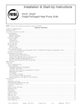
Fig. 1--Unit PHIZ
SAFETY CONSIDERATIONS
h_stallation and servicing of airoconditioning equipment can be hazardous due to system pressure and electrical components Only trained and
qualified workers should install, repair, or service air-conditioning equipment
Untrained workers can peribnn basic maintenance fkmctions of cleaning coils and filters. All other operations should be performed by trained
service people. When working on air-conditioning equipment, pay attention to precautions in the literature, tags, and labels attached to the unit,
and other sai)ty precautions that may apply.
Follow all safety codes. Wear safety glasses and work gloves. Use quenching cloth fbr unbrazing operations. Have fire extinguisher available for
all brazing operations.
z2x WARNmNG: Before performing service or maintenance operations on system, turn off main power to unit and install
lockout tag. Turn off accessory heater power switch if applicable. Electrical shock can cause serious injury or death.
Recognize sat)ty in%rmation. This is the sat_ty-alert symbol Z_. When you see this symbol in insm/ctions or manuals, be alert to the potential
fbr personal injury.
Understand the signal words DANGER, WARNING, CAUTION, and NOTE. These words are used with the safety-alert symbol. DANGER
identities the most serious hazards which will resuh in severe personal injuo' or death. WARNING signifies a hazard which could result in personal
injury or death. CAUTION is used to identit_ unsafe practices which would result in minor personal injury or product and property damage. NOTE
is used to highlight suggestions which will result in enhanced installation, reliability, or operation.
These instructions cover n_inin_tnn requirements and conIbrm to existing national standards and safety codes. In some instances, these instructions
exceed certain local codes and ordinances, especially those that may not have kept up with changing residential construction practices. We require
these instructions as a minimum for a safk installation.
BNTRODUGTmON
PH1Z heat pmnp units are fully self-contained and designed ibr outdoor installation (See Fig 1). As shown in Fig. 2°4, units are shipped in a
horizontalodischarge configuration fbr installation on a groundolevel slab. All units can be field-converted to downflow discharge configurations
for rooftop applications with a fieldosupplied plenum.
2

24_ 6
9 75]
('0_,1_
{OI -
I
P95'] 0 ......................... 408[ 6 06© ...................
REAR VIEW
..... 3S6 0 01A
1140}
DUCT OPENINGS
REQUIRED CLEARANCE TO COMBUSTIBLE MATL.
INCHES [mm}
TOP OF UNIT ......................................................................................... 0
DUCT SiDE OF UNIT ............................................................................. 0
SIDE OPPOSITE DUCTS ...................................................................... 0
BOTTOM OF UNIT ................................................................................. 0
NEC. REQUIRED CLEARANCES,
INCHES [mini
BETWEEN UNITS, POWER ENTRY SIDE .................................... 4200 11066 8I
UNITAND UNGROUNDED SURFACES, POWER ENTRY SIDE 3600 [914 0]
UNIT AND BLOCK OR CONCRETE WALLS AND OTHER
GROUNDED SURFACES, POWER ENTRY SIDE ......................... 4200 11066 8]
REQUIRED CLEARANCE FOR OPERATION AND SERVICING
INCHES [mini
CONDENSER COIL ACCESS SIDE .............................................. 30.00 [762 0]
POWER ENTRY SIDE ............................................................... 3000 [762 0]
(EXCEPT FOR NEC REQUIREMENTS)
U NIT TOP ...................................................................................... 48.00 [12192]
SIDE OPPOSITE DUCTS .............................................................. 3000 [762 0]
LEGEND
NEC - National Electrical Code
NOTES:
1 Clearances must be maintained to prevent recircuJation of air from outdoor-
fan discharge, with the exception of the condenser coil (3600 in [9140 mini A
removaNe fence or barricade requires no clearance.
2. Dimensions are in inches Dimensions irl I ] are in millimeters.
82
131 99J
wOO, ()F UN I
BLC'_,[ R, COq 1!OI O 'Z A1 ) / A_ ( O I
ACCESS P&NEL
UNIT
PN1Z024
PN1Z030
COMPRESSOR PANEL N
\\\\\\
FIELD ENTRY TO_
SERVICE PORTS _\
\\\\
LEFT SIDE VIEW
ELECTRICAL CNARACTERBSTICS
208/230-1-60
208/230-1-60,
208/230-3-60
FRONT VIEW
26.772
[I.05403
UNIT WEIGHT
tb kg
232 106
254 116
I.D x 12.7 DEEP /
[1961]
RIGHT SIDE VIEW
635
[250]
C00156
CENTER OF GRAVITY IN. (MM)
X Y Z
14.0 (356) 19.0 (483) 12.0 (305)
14.0 (356) 19.0 (483) 12.0 (305)
Fig, 2--Unit Base Dimensions, PHIZ024o030
3

241 6
29 0 _ 4080
Z222222222222ZZZZZZZZII_
.... o o
REAR VIEW
\
' 3560 )A
[4 o}
DUCT ©PES, NGS
REQUIRED CLEARANCETO DOMgUSTIBLE MATL.
INCHES [mm]
TOP OF UNiT ......................................................................................... 0
DUCT StDE OF UNIT ............................................................................. 0
SIDE OPPOSITE DUCTS ...................................................................... 0
BOTTOM OF UNIT ................................................................................. O
NEC. REQUIRED CLEARANCES.
INCHES [mrn]
BETWEEN UNITS, POWER ENTRY SIDE .................................... 4200 I066 8]
UN T AND UNGROUNDED SURFACES, POWER ENTRY S DE ¸36¸00 9 40
UNIT AND BLOCK OR CONCRETE WALLS AND OTHER
GROUNDED SURFACES, POWER ENTRY S_DE......................... 42¸00 [1066 8]
REQUIRED CLEARANCE FOR OPERATION AND SERVICING
INCHES [mini
CONDENSER COIL ACCESS SIDE .............................................. 3000 [762 0]
POWER ENTRY SIDE .................................................................... 3000 [762 0]
(EXCEPT FOR NBC REQUIREMENTS)
UNIT TOP ....................................................................................... 4800 [I 2192]
SIDE OPPOSITE DUCTS .............................................................. 3000 [762 0]
LEGEND
NEC - National Electrical Code
NOTE8:
1 Clearances must be maintained to prevent recircu[ation of air from outdoor-
fan discharge, with the exception of the condenser coil (3600 in [9140 mini A
removable fence or barricade requires no clearance
2 DimenRons are in inches Dimensions in [ ] are in millimeters
CONDE 4SE_
(0{
i,
BLC,WER, CCNIROL BOX AND
E,_#PORAIOR COIL ACCESS PANEL
COMPRESSOR PANEL
\
..9
i
26 772 I D I 12 7 DEEP J [19 61] [250]
LEFT SIDEVIEW FRONTVIEW _,o_o_
RIGHT SIDE VIEW
C00003
UNIT WEIGHT
UNIT ELECTRICAL CHARACTERISTICS
Ib kg X Y
208/230-1-60, 208/230-3-60,
PNlZ036 460-3-60 277 126 14.0 (356) 19.0 (483)
208/230_1-60, 208/230-3_60,
PNlZ042 460-3-60 295 134 14.0 (356) 19.0 (483)
208/230_1-60, 208/230-3_60,
PNlZ048 460-3-60 328 149 14.0 (356) 19.0 (483)
Fig. 3--Unit Base Dimensions, PBIZ036=048
CENTER OF GRAVITY IN, (MM)
Z
15.0(381)
150 (381)
150 (381)
4

1176
[463]
352.5
EIS.B8]
138.3
DIMENSIONS IN E] ARE IN INCHES
_352.8
[1389]
_3527
[1389]
_537
[211]
0 o
REAR VIEW
706
[27 80]
r
889
[356]
12950
[5098]
BOTTOMOF UNIT
EVAP
COND
i
\\X
LEFT SIDE VIEW
867.0
[B4.13]
8125
[BI99]
BOTTOMOF UNIT
REQUIRED CLEARANCE TO COMBUSTIBLE MATL.
INCHES [mml
TOP OF UNIT ......................................................................................... 0
DUCT SIDE OF UNIT ............................................................................ 0
SIDE OPPOSITE DUCTS ...................................................................... 0
BOTTOM OF UNIT ................................................................................. 0
NEC. REQUIRED CLEARANCES,
INCHES [mm}
BETWEEN UNITS. POWER ENTRY SIDE .................................... 4200 [1066.8]
UNIT AND UNGROUNDED SURFACES. POWER ENTRY SIDE 3000 [914 O]
UNIT AND BLOCK OR CONCRETE W/ALLS AND OTHER
GROUNDED SURFACES, POWER ENTRY SIDE ......................... 4200 [1066 8]
REQUIRED CLEARANCE FOR OPERATION AND SERVICING
INCHES [mm]
CONDENSER COIL ACCESS SIDE .............................................. 3000 [762 0]
POWER ENTRY SIDE .................................................................. 3000 [762 O]
(EXCEPT FOR NEC REQUIREMENTS)
UNIT TOP ...................................................................................... 4800 [1219 2]
SIDE OPPOSITE DUCTS .............................................................. 3000 [76201
LEGEND
NEC - National Electrical Code
NOTES:
I Clearances must be maintained to prevent recirculation of air from outdoor-
fan discharge, with the exception of the condenser coil (3600 in [9140 mm] A
removable fence or barricade requires no clearance
2 Dimensions are in inches Dimensions in [ ] are in millimeters
_BLOWER, CONTROLBOX ANDEVAP. COIL
ACCESSPANEL
COMPRESSOR PANEL_
FIELD NTRY TO
S RTS
\
o
z
/
_ " ? 1 "
FRONT VIEW
44.5
E1.75]
E2161]
DIA. DIA
[O8B]
751.8
E29.60
30.6
EI.2O] 1981
[1961]
26772 I.D x 127 DEEr
[1OS4D] RIGHT SIDE VIEW
UNIT
PNIZ060
ELECTRICAL CHARACTERBSTICS
UNIT WEIGHT
tb kg
CENTER OF GRAVITY IN. (MM)
Y
254
[1OO]
X Z
208/230-1-60,208/230-3-60, 460-3-60 368 167 14.0 (356) 20.0 (508) 16.0 (406)
C00158
Fig. 4--Unit Base Dimensions, PHIZ060
5

RECEBVmNGANDINSTALLATION
PROCEDURE 1--CHECK EQUIPMENT
A. BDENTmFYUNmT
The unit model number and serial number are stamped on the unit identification plate. (heck this infbm_ation against shipping papers. -Veril}' that
unit voltage and amperage tisted on unit rating plate agree with power supplied tbr equipment.
B. BNSPECT SHPMENT
Inspect fbr shipping damage while unit is still on shipping pallet. It"unit appears to be damaged or is torn loose fi'om its securing points, have it
examined by transportation inspectors beibre removal. Fop.yard claim papers directly to transportation company. Manu_tcturer is not responsible
fbr any damage incurred in tlansit.
(beck all items against shipping tist. Immediately notify the nearest Payne Air Conditioning ofi[lce if"any item is missing
To prevent loss or damage, 1cave all parts in original packages until installation
PROCEDURE 2--PROVmDE UNiT SUPPORT
A, SLAB MOUNT
Place the unit on a rigid, level surplice, suitable to support the unit weight. A concrete pad or a suitable fibe*glass mounting pad is recommended
The flat su*_hce should extend approximately 2=in beyond the unit casing on the 2 sides The duct connection side and condensate &ain connection
sides should be flush with the edge of the flat surface.
A 6-in. wide gravel apron should be used around the flat surfitce to prevent airflow blockage by grass or shrubs. Do not secure the unit to the flat
sur_tce except where required by local codes.
The unit should be level to within 1/4 inch. This is necessary fbr the unit &ain to fimction properly.
B. GROUND MOUNT
7he unit may also be installed directly on the ground if local codes pem_it. Place unit on level gronnd prepared with gravel for condensate
discharge.
PROCEDURE a--PROVIDE CLEARANCES
The required minimum sma'ice clearances and clearances to combustibles are shown in Fig. 2-4. Adequate ventilation and outdoor coil air must
be provided.
The outdoor fire pulls air through the outdoor coil and discharges it through the fan on the top cover. Be sure that the _hn discharge does not
recirculate to the outdoor coil. Do not locate the unit in either a corner or under an overhead obstruction. The minimum clearance under a partial
overhang (such as a normal house ovmhang) is 48 in. above the unit top. The maxin-mm horizontal extension of a partial overhang must not exceed
48 inches.
Do not place the unit whine water, ice, or snow fiom an overhang or roof will damage or flood the unit The unit may be installed on wood flooring
or on Class A, B, or ( roof cove*lug materials.
A CAUTION: Do not restrict outdoor con airflow. An air restriction at either the outdoor-air inlet or the fan discharge can
be harmful to compressor life.
PROCEDURE 4--PLACE UNBT
Lnit can be moved with the rigging holds provided in the unit base Refer to Table 1%r operating weights. Use extreme cazltinn tn prevent dare, age
_hes_ mo_,is_g the _mit. Uvit m_/st remai_ i_ a_ _lzn'ig,ht fln,sitio'n d_frmg ale mo_mg ope_'ation,s. The unit must be level with in 1/4" for proper
condensate &ainage; the ground-level pad must be level befbre setting the unit in place. When a field-[Sbricated support is used, be sure that the
support is level and that it properly supports the unit.
PROCEDURE 5--SELECT AND mNSTALL DUCTWORK
7he design and installation of the duct system must be in accordance with:
the standards of the NFPA (National Fire Protection Association) [br installation of nonresidence-type air conditioning and ventilating systems
NFPA90A or residence-type, NFPA90B: and/or local codes and residence=type, NFPA 90B
and/or local codes and ordinances
Select and size ductwork, supply=air registers and return-air grilles according to ASHRAE (American Society of Heating, Refrigeration, and Air
Conditioning Engineers) recommendations.
Use the duct flanges provided on the supply° and returnoair openings on the side of the unit. See Fig. 2-4 _br connection sizes and locations. The
14=in. round duct collars (size 024-048 units) are shipped inside t!-_eunit attached to the indoor blower. They are field-installed and must be
removed t'rom the indoor cavity prior to start-up, even if they are not used for installation.
A. BNSTALL FLANGES FOR DUCTWORK CONNECTIONS (PHIZ060 ONLY)
The PH1Z060 units are shipped with _'langes which must be field=installed on the unit.
To install unit flanges:
1. Five pieces of flange are shipped on the return=air opening of the unit Remove the flanges fiom the shipping position (See Fig. 5). Screws
are field°supplied.
2. One piece of flange is used as it is shipped (stlaight) Bend the other 4 pieces at right angles
3. Install the stlaight flange on the right side of the return°air opening in holes provided. (See Fig 6). Flanges should stick out from unit to
allow for connection of dnctwork.
6

4 Install2 hando%m_ed flanges onto return air opening in holes provided to %m_ a rectangle aronnd the remm air opening
5 Install remaining 2 handoformed flanges around discharge air opening in holes provided
6. Ductwork can now be attached to flanges.
When designing and installing ductwork, consider the following:
L,_ CAUTION: When connecting ductwork to units, do not drii[ deeper than 3/4 inch in shaded area shown in Fig. 7 or coi[
may be damaged.
* All units should have field-supplied filters installed in the returnoair side of the unit. Recommended sizes %r filters are shown in Table 1.
Avoid abrupt duct size increases and reductions. Abrupt change in duct size adversely affects air per_bm_ance.
mMPORTANT: Use flexible connectors between dnctwork and unit to prevent transmission of vibration. Use suitable gaskets to ensure
weathertight and airtight seal. When electric heat is installed, use fire proof canvas (or similar heat resistant material) connector between ductwork
and unit discharge connection. If flexible duct is used, insert a sheet metal sleeve inside duct. Heat resistant duct connector (or sheet metal sleeve)
must ectend 24 in. fi'om d_e unit discharge connection flange into the dt/ctwork.
* Size ductwork tbr cooling air quantity (cfm). The mininmm air quanti w for proper electric heater operation is listed in Table 2. Heater limit
switches may trip at air quantities below those recommended.
* Insulate and weatherproof all external dnctwork. Insulate and cover with a vapor barrier all ductwork passing through conditioned spaces.
Follow latest Sheet Metal and Air Conditioning Contractors National Association (SMACNA) and Air Conditioning Contractors Association
(A(CA) minin-mm installation standards for residential heating and air conditioning systems.
* Secure all dt_cts to building structure. Flash, weatherproofS, and vibration-isolate duct openings in wall or roof according to good construction
practices.
Figure 8 shows a typical duct system with PH1Z unit installed.
FIVE PIECES OF DUCT
FLANGE ATTACHED
HERE FOR SHIPMENT
Fig. 5--Shipping Location of Duct Ftanges
(Size 060 Only)
C00005
B. CONVERTING HORIZONTAL DISCHARGE UNITS TO BOWNFLOW {VERTICAL) DISCHARGE
A WARNBNG: Before performing service or maintenance operations on system, turn off main power to unit and install
lockout tag. Turn off accessory heater power switch if applicabme. Emectrical shock can cause serious injury or death.
Lnits are dedicated side supply products. They are not convertible to vertical air supply A fieldosupplied plenum must be used to convert to vertical
air discharge.
PROCEDURE g--PROVIDE FOR CONDENSATE DISPOSAL
NOTE: Be sure that condensate-water disposal methods comply with local codes, restrictions, and practices.
Unit removes condensate through a 1 3id4oin. ID hole (using 3/4oin. OD piping or tubing) which is located at the end of the unit. See Fig. 2=4
for location of condensate connection.
Condensate water can be drained directly onto the roof in rooftop installations (where pei_aitted) or onto a gravel apron in groundotevel
installations. Install a fieldosupplied condensate tlap at end of condensate connection to ensure proper &ainage. Make sure that the outlet of the
trap is at least 1 in. lower dtan the &ain-pan condensate connection to prevent the pan fi'orn overflowing. Prime the trap with water. When using
a gravel apron, make sure it slopes away fi'om the unit.
7

HAND FORM
STRAIGHT PIECE
Fig. 6--gJanges Bnstalmed on PHIZ060 Units
C00006
Fig. 7--Area Not to Be DriJJed More Than 3/4°in.
C00007
If the installation requires draining the condensate water away fi'om the unit, install a 2°in trap using a 3/4-in. OD robing or pipe. (See Fig 9 and
10.) Make sure that the outlet of the trap is at least 1 in lower than d-_eunit &ain-pan condensate connection to prevent the pan fiom overflowing.
Prime the trap with water. Connect a drain robe using a n_inimum of 3/4-in. PVC, 3/4-in. CPVC, or 3/4-in. copper pipe (all field supplied). Do
not undersize the robe. Pitch the drain robe downward at a slope of at least 1 in. t'or every 10 t't of horizontal run. Be sure to check the drain tube
_br leaks. Prime trap at the beginning of the cooling season start-up. Allowable glues for condensate trap connection are: Standard ABS, (PVC,
or PVC cement.
8

Table I -- Physical Data
UNiT PHIZ 024 030 036 048 060
OPERATING WEBGNT (_bs) 232 254 277 328 368
COMPRESSOR TYPE
REFRIGERANT Charge (tb)
REFRBGERANT METERBNG DEVICE
OUTDOOR COIL
Rows...Fins/in.
Face Area (sq ft)
OUTDOOR-FAN MOTOR CFM
Nomina_ Rpm
Motor Np
Diameter (in.)
INDOOR COBL
Rows...Fins/in.
Face Area (sq ft)
INDOOR FAN MOTOR
B_ower Motor Size (in.)
Nominal Cfm
Rpm Range
Number of Speeds
Factory Speed Setting
Motor Np
CONNECTING DUCT SBZES
SupNy Air (in.)
Return Air (in.)
FIELD-SUPPLBED RETURN-AIR FILTERt
Throwaway (in.)
460-v motors are 2-speed or 3-speed
042
295
Scroll
R-22
3.7 I 5.8 I 5.9 I 6.6 I 9.1 I 9.7
AcutroF MSystem
Copper Tubes, Aluminum Plate Fins
1...17 2...17 2...17 2...17
7.9 6.7 11.1 12.7
1800 2000
825 1100
1/8 1/4
20 20
1._17 2...17
11.1 9.3
Pro _etter
2600 2600
1100 1100
1/4 1/4
20 20
26OO
1100
1/4
2O
32OO
1100
1/2
2O
2._15 3...15 4...15 4...15
3.1 3.1 4.4 4.9
Copper Tubes, Aluminum Plate Fins
3._15 3._15
4.0 4.0
Direct Drive
10x9
1200
800-1050
3
Low
1/2
Round
14
14
10 x 9
1400
800-1050
3
Med
1/2
10x8
1000
550-1000
3
Med
1/4
10x9
1600
1000-1100
2
Low
3/4
10x8
8OO
550-1000
3
Low
1/4
10 x 10
2000
950-1100
3
Low
1
Square
13.9 x 13.9
13.9 x 27.8
24 x 24 24 x 24 24 x 24 24 x 24 24 x 30 24 x 30
fRequired filter sizes shown are based onthe ARI (Air Conditioning and Refrigeration Institute) ratedairflow at avelocity of 300ft/min for throwaway type or 450ft/min for
high capacity type Recommended filters are 1-in thick.
PROCEDURE 7--BNSTALL ELECTRICAL CONNECTIONS
Z_ WARNING: The unit cabinet must have an uninterrupted, unbroken electrical ground to minimize the possibility of
persona[ injury if an electrical fault should occur. This ground may consist of an electrical wire connected to the unit ground
in the control compartment, or conduit approved for electrical ground when installed in accordance with NEC (Nationam
Electrical Code), ANSI (American National Standards mnstitute)/NFPA (latest edition) (in Canada, Canadian Electrical Code
CSA C22.1) and local electrical codes. Failure to adhere to this warning could result in serious injury or death.
z_ CAUTION: Failure to follow these precautions could result in damage to the unit being installed:
1. Make aH electrical connections in accordance with NEC ANSl!NFPA (matest edition) and Bocat electricam codes governing
such wiring. Bn Canada, aH electricam connections must be in accordance with CSA standard 022.1 Canadian Electrical
Code Part 1 and applicable Bocal codes. Refer to unit wiring diagram.
2. Use only copper conductor for connections between field-supplied electrica! disconnect switch and unit. DO NOT USE ALUMINUM
WIRE.
3. Be sure that high-voltage power to unit is within operating voltage range indicated on unit rating plate.
4. Insulate low-voltage wires for highest voltage contained within conduit when low-voltage control wires are run in same conduit as
high-voltage wires.
5. Do not damage internal components when drilling through any panel to mount electrical hardware, conduit, etc. On 3-phase units,
ensure phases are balanced within 2 percent. Consult local power company for correction of improper voltage and/or phase
imbalance.
A, HGHoVOLTAGE CONNECTIONS
The unit must have a separate electlical service with a field-supplied, waterproof disconnect switch mounted at, or within sight fiom the uniL Refer
to the unit rating plate for maximum/i_seicircuit breaker size and minimum circuit amps (ampacity) for wire sizing. See Table 3 for electrical data.
The field-supplied disconnect may be mounted on the unit over the high-voltage inlet hole. See Fig. 2-4.
Z_ CAUTION: Operation of unit on improper line voltage constitutes abuse and may cause unit damage that could affect
warranty.
B. ROUTING POWER LEADS BNTO UNBT
Lse only copper wire between disconnect and enit The high-voltage leads shouM be in a conduit until they enter the unit; conduit te_]aination
at the unit must be watertight. Run the highovoltage leads through the hole on the contlol box side of the unit (see Fig. 11 for location). When
the leads are inside _he unit, run leads to the conhol box (Fig. 12). For single-phase units, connect leads to the black and yellow wires; for 3-phase
units, connect the leads to the black, yellow, and blue wires (see Fig. 13).
g

FROM
POWER
77 SOURCE
1
I
024 030
600 750
pu_erW)ring
--¢ontroIWidng
"Separated_sconnectpe_NEC
@Na_ol_alElec_r4calCode required
breec rchea erwhen snge
_n_conection isnot used
Table 2--Minimum Airflow for Safe Electric Heater
Operation (CFM)
SIZE
036 ] 042 l900 1050
Fig, 8--Typical installation
048
1200
1_'(25ram) MtN.
TRAP
2" (50mm) MiN.
Fig. 9--Condensate Trap (Using Tubing)
1" rain.
TRAP
OUTLET
T
C00008
060 1
1500
C99013
Fig. 10-PVC Condensate Trap
C00009
C. CONNECTING GROUND LEAD TO UNiT GROUND
Refer to Fig 12 and 13_ (onnect the ground lead to the chassis using the unit ground tug in the control box
D. ROUTING CONTROL POWER WIRES
Form a drip-loop with the thermostat leads before routing them into the unit Route the thermostat leads through grommeted hole provided in unit
into unit control box (See Fi b 11). Connect thermostat leads and unit power leads as shown in Fig. 13 & 14.
Route thermostat wires through grommet providing a drip-loop at the panel Connect low-voltage leads to the thermostat as shown in Fig. 14.
The unit transformer supplies 24-v power fbr complete system including accessory electrical heater. Transfbm_er is _actory wired t'or 230-v
operation. If supply voltage is 208 v, rewire tran@ormer primary as described in the Special Procedures for 208-v Operation section below.
E. ACCESSORY ELECTRIC HEAT WIRING
Re_r to accesso_- electric heat installation instructions for infom_ation on installing accesso_" electric heat Accesso_" electric heat wiring is
shown in Fig. 15A & 15B.
i0

F. SPECIAL PROCEDURES FOR 208oV OPERATION
A WARNING: Make sure that the power suppmy to the unit is switched OFF and instal1 lockout tag before making any
wiring changes. Electrical shock can cause serious injury or death.
1. Remove wirenut from connection of ORG wire to BLK wire Disconnect the ORG transl\_rmer-primary lead fi'om the BLK wire. Save
wirenut See unit wiring label.
2 Remove the wirenut fi'om the terminal on the end of the RED transfom_er-prinlary lead.
3 Save the wirenut.
4 Connect the RED lead to the BLK wire fi'om which the ORG lead was disconnected. Insulate with wirenut flora Step 1.
5 Ersing the wirenut removed fi'om d_e RED lead, insulate the loose tem_inal on the ORG lead
6 Wrap the wirenuts with electrical tape so that the metal terminals cannot be seen
Indoor blower-motor speeds may need to be changed for 208-v operation. RefBr to Indoor Airflow and Airflow A({iustments section. (See Table
of (ontents for page number.)
PRE°START-UP
Z_ WARNING: Failure to observe the following warnings could result in serious injury or death:
1. Follow recognized safety practices and wear protective goggles when checking or servicing refrigerant system.
2. Do not operate compressor or provide any electric power to unit unless compressor terminal cover is in place and secured.
3. Do not remove compressor terminal cover until aH electrical sources are disconnected and lockout tag is installed.
4. Relieve a[[ pressure from both high- and Bow-pressure sides of the system before touching or disturbing anything inside
terminal box if refrigerant leak is suspected around compressor terminals. Use accepted methods to recover refrigerant.
5. Never attempt to repair soldered connection white refrigerant system is under pressure.
6. Do not use torch to remove any component. System contains oH and refrigerant under pressure. To remove a component,
wear protective goggles and proceed as follows:
a. Shut off electrical power to unit and install lockout tag.
b. Relieve aH refrigerant from system using both high- and low-pressure ports. Use accepted methods to recover
refrigerant.
c. Cut component connecting tubing with tubing cutter and remove component from unit.
d. Carefully unsweat remaining tubing stubs when necessary. Oil can ignite when exposed to torch flame.
[se the Start:Up Checklist supplied at the end of this book and proceed as follows to inspect and prepare the unit for initial start:up:
1. Remove all access panels.
HIGH-VOLTAGE LOW-VOLTAGE
POWER WIRING WIRING ENTRY
ENTRY HOLE HOLE
;i;./ ..............................,.' IZIIIII%....................\--
C00010
Fig. ll--Unit Electrical Connection
2. Read and follow instructions on all DANGER, WARNING, CAUTION, and INFORMATION labels attached to, or shipped with, unit.
Make the following inspections:
a. Inspect fbr shipping and handling damages such as broken lines, loose parts, disconnected wires, etc.
b. Inspect _br oil at all reti'igerant tubing connections and on unit base. Detecting oil generally indicates a refrigerant leak. Leak-test all
rei'rigerant tubing connections using electronic leak detector, or liquid-soap solution. If a refi'igerant leak is detected, see following Check
for Refi'igerant Leaks section.
c. Inspect all t_eld- and factory-wiring connections. Be sure that connections are completed and tight. Ensure wires do not contact
refi'igerant robing or sheet metal edges.
11

COMPRESSOR TRANSFORMER
CONTACTOR
O O
O
o
O O
ELECTRIC GROUND INDOOR OUTDOOR FAN MOTOR HIGH
HEATER LUG FAN AND COMPRESSOR VOLTAGE
FUSES RELAY START CAPACITOR LEADS
C00011
Fig. 12--Control Box Wiring
d. Inspect coil fins. If damaged during shipping and handling, carefully straighten fins with a fin comb.
3. Verify the %llowing conditions:
a Make sm'e that outdoor-tM_ blade is CO,Teeth positioned in fhn orifice Top edge of blade should be 3125 in down t'rom outdoor coil
outlet grille (size 024 048, See Fig. 21) or hub should be 0.70%in. away fi'om motor end bell (size 060, See Fig. 22). See Outdoor Fan
Adjustment section.
b. Make sure that air filter is in place.
c. Make sure that condensate &ain trap is filled with water to ensure proper drainage.
d. Make sure that all tools and miscellaneous loose parts have been removed.
START-UP
Use the Start=L p Checklist supplied at the end of this book and proceed as follows:
PROCEDURE I--CHECK FOR REFRIGERANT LEAKS
A. LOCATE AND REPAIR REFRIGERANT LEAKS AND CHARGE THE UNIT AS FOLLOWS:
1, Lsing both high- and tow-pressm'e ports, locate leaks and reclaim remaining refi'igerant to relieve system pressure,
2, Repair 1oak %ltowing accepted practices,
NOTE: Install a liquid=line filter &ie* whenever the system has been opened for repair
PROCEDURE 2--START-UP COOLING SECTION AND MAKE ADJUSTMENTS
Z_X CAUTION: Complete the required procedures given in the PreoStart- Up section this page before starting the unit, Do
not jumper any safety devices when operating the unit.
Do not operate the compressor when the outdoor temperature is below 40 F,
Do not rapid-cycle the compressor. Allow 5 minutes between "on" cycles to prevent compressor damage.
A. CHECKING COOLING CONTROL OPERATION
Start and check the unit %r proper cooling control operation as %llows:
1. Place room thermostat SYSTEM switch in OFF position Obsmwe that blower motor starts when FAN" switch is placed in ON position and
shuts down within 30 seeconds when FAN switch is placed in AUTO position
2. Place SYSTEM switch in COOL position and FAN switch in AUTO position. Set cooling control below room temperature Observe that
compressor, outdoor tim,and indoor blower motors start and that reversing valve shifts. Observe that cooling cycle shuts down when contloi
setting is satisfied. Reversing valve (RV) remains energized.
3. Place system switch in HEAT position. Observe that compressor, indoor tMa and outdoor fire energize (Reversing Valve is deenergized in
heat pump heating mode). Set control above room temperature. Observe that heating cycle shuts down when control setting is satisfied.
12

GROUND
[S'NGLE-PHASE []-_ LEAD
3-PHASE |CONNECTIONS q
CONNECTIONS ITO DISCONNECT1 .
TO DtSCONNECT1PER NEC L_-
PER NEC | L
h
UNIT GROUND
- -L]_]
Fig, 13--Line Power Connections
C00012
B.
©
@
@
©
LJJ_
L_
L_
LJ_
Fig, 14--Control Connections
4 When using art automatic changeover room thermostat, place both SYSTEM and FAN switches in AUTO positions. Observe that unit
operates in Cooling mode when temperatore control is set to "call for cooling" (below room temperature), and unit operates in Heating
mode when temperature control is set to "call for heating" (above room temperature).
COMPRESSOR ROTATION
--[--
THERMOSTAT UNIT CONTROL POWER
AND SUBBASE SPLICE BOX
C99056
On 3 Phase units it is important to be certain compressor is rotating in the proper direction. To determine whether or not compressor is rotating
in the proper direction:
1. Connect service gages to suction and discharge pressure fittings.
2. Energize the compressor.
3. The suction pressure should drop and the discharge pressure should rise, as is normal on any start-up.
[f the suction pressure does not &op and the discharge pressure does not rise to normal levels:
1. Turn off power to the unit and tag disconnect.
2. Reverse any [wo of the unit power leads.
3. Turn on power to the unit.
The suction and discharge pressure levels should now move to their normal start-up levels.
NOTE: When the compressor is rotation in the wrong direction, the unit makes an elevated level of noise and does not provide cooling.
PROCEDURE 3--REFRIGERANT CHARGE
Refrigerant (harge Amount of refrigerant charge is listed on unit nameplate and in Table I. Re_I [o Payne Ret'rigerant Service Techniques
Manual, Refrigerants section. Unit panels must be in place when unit is operating during charging procedure. Unit must operate a minin_um of
15 minutes befbre checking charge.
A. NO CHARGE
RefeI to Payne Ret'rigerant Service Techniqnes Use standard evacuating techniques. At'ter evacuating system_ weigh in the specified amount of"
refi'igerant (refer to Table 1).
B. LOW CHARGE COOLmNG
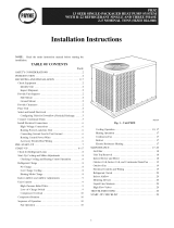
[sing cooling charging chart (see Fig. 16 2 I)_Vary rei?igerant until conditions of the chart are met. Note that charging chart is different fiom those
normally used (harts are based on charging the units to the con'ect superheat [br the various operating conditions An accurate pressure gage and
temperature-sensing device is required Connec_ the pressure gauge to the service port on the suction line Connect temperature sensing device to
the suction line near the compressor and insulate it so 4]at outdoor ambient temperature does not affkct reading.
C. TO USE THE COOLING CHARGING CHART
This method is to be used in cooling mode only. Take the outdoor ambient temperature and read the suction pressure gauge. Refer to charts to
determine what the suction temperature should be. If suction temperature is high, add refrigerant. If suction temperatore is low, carefully recover
some of the charge. Recheck the suction pressure as charge is adjusted.
Example: (See Fig. 16)
Outdoor Temperature 85°F
Suction Pressure74 psig
Suction Temperature should b_60_T
Note Suction Temperature may vary +/- 5°F
D. HEATING NODE CHARGE
Do not attempt to adjust charge by cooling methods while in heat pump heating mode Recover refi'igerant and weigh in according to unit data
plate refi'igerant data.
PROCEDURE 4--mNDOOR AIRFLOW AND A_RFLOW ADJUSTMENTS
NOTE: For cooling operation, the recommended airflow is 350 to 450 cfm per each 12,000 Btuh of rated cooling capacity.
Table 4 shows dW coil air delive W for horizontal discharge traits. Tables 5-7 show pressure drops_
NOTE: Be sure that all supply= and return-air grilles are open, fi'ee fiom obstructions, and adjusted properly.
Z_ WARNING: Disconnect electrical power to the unit and install lockout tag before changing Mower speed. Electrical
shock can cause serious injury or death.
Airflow can be changed by changing the lead connections of the blower motor.
13

_m_EL_
MAXIMUM WIRE _ EQUIP GNO
SIZE 2 AWG _ Pi_
SUPPLY
USED WITH
ACCESSORY
ELECTRIC HEAT
OPTION ONLY.
USED WITH
HEATER OPTIONS -
S&IQKW (024 042_
SIZE 2 AWG
MAXIMUM WIRE
USED WITH
ACCESSORY
ELECTRIC HEAT
OPTION ONLY.
USED WITH
HEATER OPTIONS
S KW (048 O60)
I0 KW (O24 060)
MAX[MUM WIRE
SIZE 2/0 AWG
SCHEMATIC
208/230 1 80
BLK
IFR
C]CH F_
(024,030,042,048 _ OBO)
TDR
(030 & 042)
OT CAP1
USED WITH
ACCESSORY
ELECTRIC HEAT
15&20KW(042 060)
MAXIMUM WIRE
SIZE 2/0 AMG
-GRN BRN -- FOR UNITS
(024,030,042,048 & OGO)
090
_TEST
CTO RVS
Y BLU _ _ ............-- _
I jTPL1 _BRN __
• I b _ m _ m _ _ _ ABOVE 10.0 K.W.
[SEE NOTE#2)
NOTES
2.SEE PRICE PAGES FOR THERMOSTAT
AND SUBBASE PART NUMBERS.
3.SET HEAT ANTICIPATOR AT .6
4.USE 75_C COPPER CONDUCTORS ONLY.
YEL
SRN
24V BSoPxLI C E
COMPRESSOR OELAY
CTB m m
(TI'T2)I I I I
o_..... T .......
CLOSES OPENS
(TSTAT)
COMPONENT ARRANGEMENT
DEFROST CYCLE
OFT
FAN SEQUENCE OFf, OF . QPFN
(1,31 1 I I
.... _ ........ _RQI Z_D B0
LEGEND
_i_ _ _ I_NDOORFAF
BLOWER HOUSING
N YE
/ .....
__ _CCESSORY
r _co3_ I
........... _UWOFM
............. , ?P I .... ,__,__
EQUIPQNDJW _OX "_
--J _ m _ m m m
....1 .....................[] [] []
F[ELD SPLICE C CONTACTOR,COMPRESSOR
CAP CAPACITOR
MARKED WIRE
CB CIRCUIT BREAKER
TERMINAL (MARKED) COMP COMPRESSOR MOTOR
CTB COMPRESSOR TIME DELAY
0 TERMINAL (UNMARKED) EQUIP EQUIPMENT
[_{] TERMINAL BLOCK
FU FUSE
GND GROUND
SPL[CE
BB DEFROST BOARD
SPL[CE (MARKED) OFT DEFROST THERMOSTAT
PLUG OR DEFROST RELAY
BT DISCHARGE THERMOSTAT
**,*,,*,,*,,q_ RECEPTACLE IFR INDOOR FAN RELAY
_ INDOOR FAN MOTOR
FACTORY WIRING LOW PRESSURE SWITCH
FIELD CONTROL WIRING OFM OUTDOOR FAN MOTOR
PL PLUG
m FIELD POWER WIRING QT QUADRUPLE TERMINAL
RVS REVERS[N6 VALVE SOLENOID
m mm ACCESSORY DR OPTIONAL WIRING SB SLOW BLOW FUSE
m TO [NDICATE COMMON TBR TIME BELAY RELAY
TRAN TRANSFORMER
POTENTIAL ONLY:
NOT TO REPRESENT WIRINO
mbt?/HhttttgqtqF
C01022
Fig. 15A--Typical Unit E(ectrical Diagram (208/230-1-60)
l_ nits PHIZ024, 036, 048, and 060 blower motors are factor, wired IZ_rlow speed operation. Units PHIZ030 and 042 are fitctory wired £_rmedium
speed operation.
A. FOR 2081230oV (See Page 18}
The motor leads are coloPcoded as follows:
To change the speed of the indoor fan motor (IFM), remove the fan motor speed leg lead from the indoor _hn relay (IFR) with units 024, 030, 042,
048 & 060 or the time delay relay (TDR) on 036 size and replace with lead iZ_r desired blower motor speed./;_.s_date the *rmo*,ed Zead to re,old
co'n_act with c,/_a.s.si.sparle'
B. FOR 4gOoV MOTORS (See Page 18)
The motor leads are color coded as follows:
14

C _ - .BRN....(C,OM_AON_)
wl_.,_ - _vLo_sT_p_2L_
UNIT POWER
WIRING
FUSE BLOCK
L2_ YEL
m
|
|
l CONTACTOR 2
I l
CONTACTOR 1
EL_ AUTO-LIMIT BLK
co06RT i
Fig. 15B--Accessory Electric Heater Wiring
To change the speed of the indoor fan motor (IFM) f?om tow speed to high speed, remove the red lead flora the indoor-fhn relay (IFR). ON 2 Speed
Motors: Insulate the red lead to avoid contact with any chassis parts. Separate the black lead fl'om the purple lea& Connect the black lead to the
IFR. Insulate the pmple lead to avoid contact with any chassis parts ON 3 Speed Motors: remove the fhn motor speed leg lead ['tom the indoor
(indoor) tim relay (IFR) and replace with lead fbr desired blower motor speed
PROCEDURE 5--UNBT CONTROLS
All compressors have the fbllowing internal-protection controls.
A. HGH-PRESSURE RELIEF VALVE
This valve opens when the pressure differential between the low and high side becomes excessive (024 size has temperature relief only)
B. LOSS OF CHARGE SWITCH
Located on the outdoor liquid line is a low-pressure switch which functions as a loss-of-charge switch This switch contains a Schrader core
depressor, This switch opens at 7 psig and closes at 22 psig No adiustment is necessa W
C. COMPRESSOR OVERLOAD
This overload interrupts power to the compressor when either the cmrent or internal temperature become excessive, and automatically resets when
the internal temperature &ops to a safe level. This overload may require up to 60 minutes (or longer) to reset; therefbre, if the internal overload
is suspected of being open, disconnect the elecnical power to the unit and check the circuit through the overload with an ohmmeter or continuity
tester.
PROCEDURE 6--SEQUENCE OF OPERATION
A. FAN OPERATION
_he FAN switch on the thermostat controls indoor fhn operation. When the FAN switch is placed in the ON position, the IFR (indoor-fan relay)
is energized through the G terminal on the thermostat The normally-open contacts close, which then provide power to the indoor (evaporator) _m
motor (IFM) The IFM will run continuously when the FAN switch is set to ON
When the FAN switch is set to AUTO, the thermostat deenergizes the IFR (provided there is not a call fbr cooling). The contacts open and the
IFM is deenergized The IFM will be energized only when there is a call for cooling, in heat pmnp heating mode or if the unit is equipped with
accesso_ electric heat, the indoor=tim motor will also run while the accessory electric heat is energize&
NOTE: Some units are equipped with a time-delay relay On these units, the indoor ihn remains on i\_r 30 seconds after G or Y is deenergized
B. COOLING
With the thermostat snbbase in the cooling position, the thermostat makes circuit R-O This energizes the reversing vah-e solenoid (RVS) and
places the unit in standby condition for cooling.
NOTE: The defrost control board has a 5 minute compressor anti-short cycle time delay built in between compressor starts.
On a call for cooling, the compressor contactor (C) and d_e IFR are energized through the Y and G terminals of the thermostat Energizing the
compressor contactor supplies power to the compressor and the outdoor (condenser) tim motor (OFM) Energizing the IFR provides power to the
IFM.
When the need for cooling has been satisfied, the OFM, compressor, and IFM (FAX' on AUTO) are deenergized. If the unit is equipped with a
30-second delay (036 size only), the indoor fan will remain energized ibr 30 seconds after the compressor is deenergized The reversing valve
solenoid remains energized
C. HEAT PUMP HEATING
On a call fbr heat, thermostat makes circuits R-Y and R-G. Vv'hen compressor time delay (5-minute ÷ 2 minutes) is completed, a circuit is made
to C, starting COMP and OFM. (ircuit R-G also energizes IFR and starts IFM after 1-second delay.
15

-->
UNIT PHIZ
SIZE
(=SERIES, IF
USED)
024=311
024=321
030
038
042
048
060
V-PH-HZ
COMPRESSOR
OFM IFM
FLA FLA
RLA LRA
208/230-1-60
208/230-1-60
208/230-1-60
2081230-3-6
208/230-1-60
208/230-3-60
460-3-60
208/230-1-60
208/230-3-60
460-3-60
208/230-1-60
208/230-3-60
460-3-60
230-1-60
208/230-3-60
VOLTAGE
RANGE
MIN MAX
187 254
187 254
187 254
187 254
187 254
187 254
414 508
187 254
187 254
414 508
187 254
187 254
414 508
187 254
187 254
460-3-60 414 508
(SeeEegend fo{Iow{ng ElecMcN Data charts)
Table 3--Electrical Data--PHIZ
ELECTRIC NEAT
11.4 560 0.9 2.4
12.1 540 0.9 2.4
14.4 730 1.5 2.4
10.0 630 1.5 5.8
17.7 930 1.5 2.8
11.4 770 1.5 2.8
5.7 390 0.8 2.0
22.0 103.0 1.5 2.8
13.9 880 1.5 2.8
6.8 440 0.8 2.0
21.8 124.0 1.5 4.2
12.8 930 1.5 4.2
6.4 465 0.8 4.2
27.7 170.0 3.1 6.2
15.9 124.0 3.1 6.2
Nominal KW* FLA
4- -/-
3.8/50 183/208
5.6/75 269/31 3
75/10.0 361/417
4- -/-
3.8/50 183/208
5.6/75 269/31 3
75/10.0 361/417
4- 4-
3.8/50 183/208
5.6/75 269/31 3
75/10.0 361/417
11.3/15.0 542/625
4- -/-
3.8/50 104/120
75/10.0 208/241
11.3/15.0 313/361
4- -/-
3.8/50 181/208
5.6/75 269/31 3
75/10.0 361/417
11.3/15.0 542/625
4- -/-
3.8/50 104/120
75/10.0 208/241
11.3/15.0 313/361
5 60
10 120
15 180
4- -/-
3.8/50 183/208
5.6/75 269/31 3
75/10.0 361/417
11.3/15.0 543/625
15/20 72 1/83 3
4- 4-
3.8/50 105/120
75/10.0 208/241
11.3/15.0 314/361
15/20 41 4/479
5 80
10 120
15 180
20 241
4- -/-
3.8/50 183/208
5.6/75 269/31 3
75/10.0 361/417
11.3/15.0 542/625
15/20 722/833
4- 4-
3.8/50 105/120
75/10.0 208/241
11.3/15.0 314/361
15/20 41 4/479
5 60
10 120
15 180
20 241
3.8/5 183/208
5.6/75 269/31 3
75/10 361/41 7
11.3/15 543/625
15.0/20 721/833
4- 4-
3.8/50 105/120
75/10.0 208/241
11.3/15.0 314/361
14.9/19.9 414/479
5 60
10 120
15 18 0
19.9 239
MCA
176/176
404/436
51 2/567
627/697
184/184
41 3/444
521/576
636/706
21 9/21 9
448/479
555/61 0
670/740
898/100.0
168
299/31 8
428/469
561/61 9
264/264
493/524
601/656
746/786
943/104.6
186/186
31 7/336
446/487
578/637
99
174
249
324
31 8/31 8
547/578
654/709
769/839
997/109.9
1219/135.9
21 7/21 7
348/367
47 7/51 8
609/668
734/81 6
113
188
263
338
41 4
330/330
558/590
666/721
781/851
1008/111.1
1231/137.1
21 7/21 70
348/367
477/51 8
61 0/668
735/81 6
109
184
259
334
408
439/439
668/699
776/831
891/961
1118/122.1
1341/148.1
292/292
423/442
552/593
684/743
809/891
147
222
297
372
446
SINGLE POINT POWER SUPPLY
MOCP
FUSE OR
CKT BKR
25/25
45/45
60/60
25/25
45/45
60/60
30/30
45/50
60/-
8.0 598 1.5 3.2
20
35/35
45/50
60/-
35/35
50/60
25/25
35/35
45/50
60/-
15
2O
25
35
40/40
60/60
30/30
35/40
50/50
15
2O
3O
35
45
40/40
60/60
25/25
35/40
50/60
15
2O
3O
35
45
60/60
35/35
45/45
60/60
2O
25
3O
4O
45
70/70
70/80
-/70
70/80
90/110
-/70
70/70
80/80
100/110
-/70
70/80
80/90
100/110
125/150
70/70
80/90
70/80
80/90
110/125
125/150
70/70
80/90
70/70
80/90
90/100
125/125
150/150
70/80
90/90
Should room temperature continue to fall, circuit R-W is made through seco*ad-stage d_etw_ostat bulb, If optional electric heat package is used, a
relay is energized, bringing on first bank of supplemental electric heat, When thermostat is satisfied, contacts open, deenergizing contactor and
relay; motors and heaters deenergize, The IFM may be controlled by a timeodelay relay that keeps the fan on for 30 seconds,
id

LEGEND
FLA -- Fult Load Amps
LRA -- Locked Rotor Amps 1,_
MCA -- Minimum Circuit Amps
MOCP -- Maximum Overcurrent Protection
RLA -- Rated Load Amps
CKT BKR -- Circuit Breaker
NOTES:
1. In compliance with NEC (National Electrical Code) requirements
for multimotor and combination toad equipment (refer to NEC
Articles 430 and 440), the overcurrent protective device for the
unit shall be Power Supply fuse. Canadian units may be
fuse or circuit breaker.
2. Minimum wire size is based on 60 C copper wire. If other than
60 C wire is used, or if tength exceeds wire length in table,
determine size from NEC.
3. Unbalanced 3-Phase Supply Voltage
Never operate a motor where a phase imbalance in supply volt-
age is greater than 2%. Use the following formula to determine
the percentage of voltage imbalance.
% Voltage imbalance
= 100 x max vottage deviation from average voltage
average vottage
EXAMPLE: Supply voltage is 460-3-60.
A B C AB = 452 v
BC = 464 v
AC = 455 v
Average Voltage =
452 + 464 + 455
3
1371
3
= 457
Determine maximum deviation from average voltage.
(AB) 457 452=5v
(BC) 464 457=7v
(AC) 457 455=2v
Maximum deviation is 7 v.
Determine percent of 'voltage imbalance.
7
% Voltage Imbalance = 100 x --
457
= 1.53%
This amount of phase imbalance is satisfactory as it is below the
maximum allowable 2%.
IMPORTANT: If the supply voltage phase imbalance is
more than 2%, contact your local etectric utility company
immediate@.
c99024
4O 5O
SUCTION LINE TEMPERATURE
| JJ m J m| Jm J B m |J |HI
3O
30 40 50 60
SUCTION LINE TEMPERATURE i
70 80 90
4 10 16 21 27 32
SUCTION LINE TEMPERATURE i
Fig. 16--Cooling Charging Chart, PHIZ024 Units c00162 Fig. 17--Cooling Charging Chart, PHIZ030 c00163
D. DEFROST
Defi'ost board (DB) is a time and temperature control, which includes a fiekl-selectable time period between checks for defrost (30, 50 and 90
minutes). The time period is [hctory=set at 30 minutes and should only be adjusted by a trained service person. Electronic timer and defi'ost cycle
start only when contactor is energized and defrost thermostat (DFT) is closed.
Del:i'ost mode is identical to Cooling mode. The outdoor fan motor stops because of "OFF' and "OFT' contacts opening on the deJi'ost board, a
bank of optional electric heat turns on to warm air supplying the conditioned space.
E. ELECTRIC RESISTANCE HEATmNG
If accesso! 2- electric heaters are installed, on a call _i_)r"Emergency Heat" the thermostat energizes W which energises the heater relay and in turn
energizes the electric heaters. The IFR is energized which starts the indoor-fan motor. If the heaters are stage& W2 is energized when the second
stage of heating is required. When the need for heating is satisfied, the heater and IFM are deenergized.
MAINTENANCE
To ensure continuing high perfbm_ance, and to reduce the possibility of prenmmre eqtdpment failure, periodic nmintenance must be performed
on this equipment. This cooling unit should be inspected at least once each year by a qualified sela'ice person. To troubleshoot cooling of units,
refer to Troubleshooting chart in back of book.
17

683 O0 _ ....
_UTDOOR TEMF
>F C
115 46
621 i 90 105 41
i 95 35
552 80 7585 2429
483 70 5565 1318 --
414 60 45 7....
s45:s0
276 40
207m 30
3'0 4'0 ?o 60 7o do ?o
SUCTION LINE TEMPERATURE (°F}
m m I m m m m
-1 4 10 16 21 27 32
SUCTION LINE TEMPERATURE(°C)
18--Coolin¢
PHIZ036 Unit 000164
80 90
SUCTION LINE TEMPERATURE('C
.20--Coolin_ PHIZ048 Unit c00166
oo E
552 80 _
483 70
414 60
345 i 50
276 40
207m 30
£ 4_ _ do 7_ b
SUCTION LINE TEMPERATURE {°F)
| | I | m | m
-1 4 10 16 21 27 32
SUCTION LINE TEMPERATURE(°C)
C00165
Fig. 19--CooJing Charging Chart, PHIZ042 Units
£ 4_ 5'0 do 7_ 8'o 9'0
SUCTION LiNE TEMPERATURE (°F)
| | I | m | m
-1 4 10 16 21 27 32
SUCTION LINE TEMPERATURE(°C)
FOR 208/230oV
The motor leads are color-coded as %llows:
3-SPEED
Mack = high speed
b_ue = medium speed
red = _ow speed
FOR 460oV MOTORS
The motor leads are color coded as fbltows:
3oSPEED (0g0 ONLY)
Mack = high speed
Fig. 21--CooJing Charging Chart, PHlZ060 Unit 0°°167
18
2-SP_:ED
black = high speed
red = low speed
2-SPEED
black = to purple
yeltow= line
orange = medium speed purple = to black
b_ue = low speed red = line

NOTE T() EQI. IPMENT OWNER: Consult your local dealer about the availability of a maintenance contract.
Z_x WARNING: The ability to properly perform maintenance on this equipment requires certain expertise, mechanical
skills, tools and equipment. If you do not possess these, do not attempt to perform any maintenance on this equipment, other
than those procedures recommended in the User's Manual. FAILURE TO HEED THBSWARNmNG COULD RESULT IN SERIOUS
mNJURY, DEATH OR DAMAGE TO THIS EQUIPMENT.
The mininmm maintenance requirements %r this equipment are as %llows:
1 Inspect air filter(s) each month. Clean or replace when necessary.
2 Inspect indoor coil, outdoor coil, drain pan, and condensate drain each cooling and heating season fbr cleanliness. (lean when necessary.
3 Inspect blower motor and wheel for cleanliness each cooling and heating season. Clean when necessary. For first heating season, inspect
blower wheel bimonthly to determine proper cleaning frequency
4 Check electrical connections for tighmess and controls _br proper operation each cooling season Service when necessary
5 Check the &ain channel in the top cover periodically _br blockage (leaves, insects). (lean as needed.
Z_ WARNBNG: Failure to follow these warnings could result in serious injury or death:
1. Turn off electrical power to the unit and install lockout tag before performing any maintenance or service on the unit.
2. Use extreme caution when removing panels and parts. As with any mechanical equipment, personal injury can result from
sharp edges, etc.
3. Never place anything combustible either on, or in contact with, the unit.
PROCEDURE I--AIR FILTER
NOTE: Never operate the unit without a suitable air filter in the return-air duct system. Always replace the filter with the same size as originally
installed. See Table 1 for recommended filter sizes
Inspect air filter(s) at least once each month and replace (throwawayqype) or clean (cleanable-type) at least twice during each cooling season or
whenever the filters become clogged with dust and lint.
Replace filters with the same dimensional size and type as originally provided, when necessa_'.
PROCEDURE 2--UNIT TOP REMOVAL (OUTDOOR-COIL SIDE)
NOTE: When per[orn_ing n_aintenance or service procedures that require ren_oval of d-_eunit top, be sure to perform all of the routine n_aintenance
procedures that require top removal, including coil inspection and cleaning, and condensate drain pan inspection and cleaning.
Z_ WARNING: Disconnect and tag e[ectNca[ power to the unit before removing top. Failure to adhere to this warning
could cause serious injury or death,
Only qualified service personnel should per%tin maintenance and service procedures that require unit top removal
Refer to the following top removal procedures:
1. Remove 7 screws on unit top cover surface. (Save all screwsh
2. Remove 2 screws on unit top cover flange. (Save all screwsh
3. Lift top fi'om unit carefully. Set top on edge and make sure that top is supported by unit side that is opposite duct (or plenum) side.
4. Caret\ally replace and secure unit top to unit, using screws removed in Steps 1 and 2_ when maintenance and/or service procedures are
complete&
PROCEDURE 3--INDOOR BLOWER AND MOTOR
For longer ti_, operating economy, and continuing eft_ciency, clean accumulated dirt and grease flora the blower wheel and motor annually.
Z_ WARNING: Disconnect and tag electrical power to the unit before cleaning the blower wheel. Failure to adhere to this
warning could cause serious injury or death,
To clean the blower wheel:
1. Access the blower assembly as %tlows:
a. Remove top access panel
b. Remove 3 screws that hold blower orifice ring to blower housing. Save screws.
c. Loosen setscrew(s) which secure wheel to motor shaft.
2. Remove and clean blower wheel as follows:
a. Lift wheel from housing. When handling and/or cleaning blower wheel, be sure not to disturb balance weights (clips) on blower wheel
vanes.
b. Remove caked-on dirt flora wheel and housing with a brush. Remove tint and/or dirt accumulations from wheel and housing with
vacuum cleaner, using a soft brush attachment. Remove grease and oil with a mild solvent.
19

TaMe 4--Dry Coil Air Delivery* Horizontal Discharge
(Deduct 10 percent for 208 Volt Operation)
230 AND 460 VOLT
External Static Pressure (in. wg)
Unit Motor Speed Watts/CFM
0.1 0.2 0.3 0.4 0.5 0.6 0.7 0.8 0.9
Watts 288 285 282 279 274 268 261
Low
Cfm 875 820 802 734 668 582 478
Watts 390 383 378 369 360 350 340
024 Med
Cfm 1131 1090 1038 978 917 830 721
Watts 528 520 510 495 480 460 450
High Cfm 1391 1338 1285 1200 1115 1018 920
Watts 288 285 282 279 274 268 261
Low
Cfm 875 820 802 734 668 582 478
Watts 390 383 378 369 360 350 340
030 Med
Cfm 1131 1090 1038 978 917 830 721
Watts 528 520 510 495 480 460 450
High Cfm 1891 1338 1285 1200 1115 1018 920
Watts 450 435 420 400 380 335 326 31I
Low
Cfm 1231 1218 1204 1120 1008 950 863 751
Watts 470 450 445 410 388 359 338 321
0S6 Med
Cfm 1302 1264 1205 1163 1081 940 873 783
Watts 660 635 610 575 540 505 485 460
High Cfm 1700 1660 1581 1450 1297 1190 1095 999
Watts 478 458 440 411 378 350 327 317
Low
Cfm 1303 1270 1224 1179 1126 1022 911 816
Watts 481 468 450 438 404 370 338 320
042 1" Med
Cfm 1310 1280 1241 1181 1110 1022 943 811
Watts 798 678 647 618 578 540 500 460
High Cfm 1736 1688 1618 1510 1421 1309 1187 1060
Watts 801 760 730 688 650 600 570
Low
Cfm 1898 1841 1757 1682 1564 1429 1333
Watts
048 1" Med
Cfm
Watts 870 842 818 782 696 632 628
High Cfm 2000 1903 1799 1718 1625 1446 1365
Watts 890 850 810 790 735 680 580 480 422
Low
Cfm 1834 1820 1791 1762 1703 1640 1415 1159 950
Watts 1040 1018 1000 950 890 835 790 650 580
060 1" Med
Cfm 2230 2102 2025 1960 1901 1855 1752 1468 1121
Watts 1073 1038 1001 958 896 840 800 691 575
High Cfm 2230 2202 2160 2122 2052 1926 1791 1588 1202
460-v motors are 2-speed
Air delivery values are based on operating voltage of 230-v or 460-v, dry coil, without filter or electric heater Deduct wet coil filter, and electric heater pressure drops to
obtain external static pressure availabe for ducting.
Do not operate the unit at a cooling airflow that is less than 350 cfm for each 12,000 Btuh of rated cooling capacity. Evaporator coil frosting may occur at airflows below this
point.
Dashes indicate portions of the table that are beyond the blower motor capacity or are not recommended
c Reassemble blower into housing. Place upper orifice ring on blower to judge location of the blower wheel. Blower wheel should be
approximately 0.2-in. below bottom of orifice ring when centered correctly Be sure setscrews are tightened on motor and are not on
round part of sha_l.
d. Set upper orifice ring in place with 3 screws removed in step 1.
e. Replace top access panel.
PROCEDURE 4--OUTDOOR COIL, mNDOOR COIL, AND CONDENSATE DRAIN PAN
Inspect d-le outdoor coil, indoor coil, and condensate drain pan at least once heating and cooling season. Proper inapection and cleaning requires
the removal of the unit top See Unit Top Removal section abo_e
Remove all obstructions (including weeds and shrubs) that interfere with the airflow through the outdoor coil Straighten bent fins with a fin comb
If coated with dirt or tint, clean the coils with a vacuum cleaner, using a sot_ brush attachment Be careful not Gobend the fins If coated with oil
or grease, clean the coils with a mild detergentoandowaterosolution Rinse coils with clear water, using a garden hose Be careful not to splash water
on motors, insulation, wiring or air filter(s). For best results, spray outdoorocoil fins t'rom inside to outside the unit. On units with an outer and
inner outdoor coil, be sure to clean between the coils. Be sure to flush all dirt and debris _i'om the unit base.
Inspect d_e &ain pan and condensate drain line when inspecting the coils. Clean the &ain pan and condensate drain by removing all foreign matter
fi'om the pan. Flush the pan and drain robe with clear water. Do not splash water on the insulation, motor, wiring, or air filter(s). If the drain tube
is restricted, clear it with a "plumbers snake" or similar probe device. Ensure that the auxiliary &ain port above the drain robe is also clear.
2O
/