Page is loading ...

CONTENTS
Page
SAFETY CONSIDERATIONS ...................... 1-5
I. General ................................... 1
RECEIVING AND INSTALLATION ................. 6 15
I. Step 1 -- Check Equipment .................. (3
II. Step 2 -- Provide Unit Support ............... (3
III. Step 3 -- Field Fabricate Ductwork ............ (3
IV. Step 4 -- Provide Clearances ................. 6
V. Step 5 -- Rig and Place Unit ................. 6
VI. Step 6 -- Connect Condensate Drain .......... 9
VII. Step 7 -- Install Flue Hood ................... 9
VIII. Step 8 -- Install Gas Piping .................. 9
IX. Step 9 -- Install Duct Connections ........... 11
X. Step 10 -- Install Electrical Connections ...... 13
PRE-START-UP ................................. 1(3
START-UP .................................... 16 29
I. Check for Refrigerant Leaks ................. 1(3
II. Start-Up Heating Section and
Make Adjustments ......................... 17
III. Start-Up Cooling Section and
Make Adjustments ......................... 20
MAINTENANCE ................................ 3043
I. Air Filter .................................. 30
II. Unit Top Removal .......................... 30
III. Evaporator Blower and Motor ................ 30
IV. Flue Gas Passageways ..................... 31
V. Combustion-Air Blower ..................... 31
VI. Limit Switch .............................. 31
VII. Burner Ignition ............................ 31
VIII. Main Burners ............................. 32
IX. Condenser Coil, Evaporator Coil, and
Condensate Drain Pan ..................... 32
X. Condenser Fan ............................ 33
XI. Electrical Controls and Wiring ............... 33
Xll. Refrigerant Circuit ......................... 33
Xlll. Gas Input ................................. 33
XlV. Evaporator Airflow ......................... 33
XV. Metering Device -- Acutrol TM Device .......... 33
XVI. Liquid Line Strainer ........................ 33
TROUBLESHOOTING ........................... 34-3(;
START-UP CHECKLIST .......................... CL 1
NOTE TO INSTALLER -- Before the installation, READ
THESE INSTRUCTIONS CAREFULLY AND COMPLETELY.
Also, make sure the User's Manual and Replacement Guide
are left with tile unit after installation. The furnace is NOT
to be used for temporary heating of buildings or structures
under constrttction.
SAFETY CONSIDERATIONS
Installation and servicing of air-conditioning equipment can
be hazardous due to system pressure and electrical compo
nents. Only trained and qualified personnel should install,
repair, or service air conditioning equipment.
Cancels: II PY1P 18 1 II PY1P 18 2
9/1/98
Fig. 1 -- Unit PY1P
Untrained personnel can perform basic maintenance flmc-
tions of cleaning coils and filters. All other operations should
be performed by trained service personnel. When working on
air conditioning equipment, observe precautions in the lit
erature, tags and labels attached to the unit, and other safety
precautions that may apply.
Follow all safety codes. Wear safety glasses and work gloves.
Use quenching cloth for unbrazing operations. Have fire ex-
tinguisher available for all brazing operations.
I. GENERAL
The PY1P units (see Fig. 1) are fidly self-contained, combi-
nation Category I gas heating/electric cooling units designed
for outdoor installation. See Fig. 2 5 (pages 2 5) for unit di-
mensions. All unit sizes have discharge openings for both hori
zontal and downflow configurations, and are factory shipped
with all 4 duct openings covered. Units may be installed ei-
ther on a rooftop or a groundqevel cement slab. See Fig. 6 for
roof curb dimensions.

/-COND COIL
- 4 13/16"
()22.2) 43 11116"
4ll0B.B)
B/16 °
(312.?)
\
BLOWER ACCESS BURNER AND CONTROL 30X
PANEL RIGHT SIDE VIEW ACCESS PANEL
REQ'D CLEARANCES FOR SERVICING in (mm)
Duct panel ............................. 0
Unit top ........................... 36 (914)
Side opposite ducts ..................... 36 (914)
Compressor access ..................... 36 (914)
(Except for NEC requirements)
REQ'D CLEARANCES TO COMBUSTIBLE MAT'L in. (mm)
Maximum extension of overhangs ............... 48 (1219)
Unit top ........................... 14 (356)
Duct side of unit ........................ 2 (51)
Side opposite ducts ..................... 14 (356)
Bottom of unit ........................... 0
Flue panel ......................... 36 (914)
NEC REQ'D CLEARANCES in. (mm)
Between units, control box side ................ 42 (1067)
Unit and ungrounded surfaces, control box side ......... 36 (914)
Unit and block or concrete walls and other grounded
surfaces, control box side .................. 42 (1067)
49 9116"
(1259.3)
COIL
RETURN
AIR OPENING
(281,4) I
l? l/1B'_
(433,9)
LOPT_ONAL SUPPLY
AIR OPENING
14 ?liB"
(365.9)
(52,63
10 9116"
(263.R)
7/3" (22.2) BIA,
CONTROL ENTRY_
\
t (203.2)
€
I 1/8" (2B.6) DIA,
POWER ENTRY
_ (90.51 i
i !
_-I 5/E _ 441,3) OIA.
GASENTRY
1/2 _ - 14 NPT
GASCONNECTION
REAR VIEW
i w (58.O)
! I
(29.6)
FLUE PANEL
FLUE HOOD
0 ?/3" 422.23)
ALTERNATE LV ENTRY
EVAP COIL ACCESS
LEFT SIDE VIEW
I W4" (31.75)
_,ALTERNATE POWER ENTRY
I ?/16 -2 3/18"
(39.3) 455.6)
COMPRE330R ACCES5 PANEL
3/4" NPT (13,0)
DRAIN OUTLET
FRONT VIEW
UNIT
PYIP180040
PY1P024040
PYIP024060
PY1P030040
PYIP030060/080
PYIP036060/080
PYIP036100/120
PYIP042060/080
PYIP042100/120
ELECTRICAL
CHARACTERISTICS
208/230-1-60
208/230-1-60
208/230-1-60
208/230-1-60, 208/230-3-60
208/230-1-60, 208/230-3-60
208/230-1-60, 208/230-3-60, 460-3-60
208/230-1-60, 208/230-3-60, 460-3-60
208/230-1-60, 208/230-3-60, 460-3-60
208/230-1-60, 208/230-3-60, 460-3-60
UNIT WEIGHT
Ib kg
272 123
303 138
315 143
320 145
332 149
336 153
348 158
375 170
387 176
CORNER WEIGHT UNIT HEIGHT
(Ib/kg) (in./mm)
A B C D E
81/37 82/28 78/35 53/24 24 1/813
97/44 43/20 123/56 40/18 241/813
100/45 46/21 128/57 43/20 241/813
100/45 47/21 128/57 47/21 241/813
103/46 50/22 129/58 50/23 24 1/813
86/39 76/35 111/50 63/29 24 1/813
89/40 79/36 114/52 66/30 24 1/613
95/43 86/39 119/54 75/34 28 1/714
98/45 89/40 122/55 78/35 28 1/714
UNIT
PYIP018040
PY1P024040
PY1P024060
PY1P030040
PY1P030060/080
PY1P036060/080
PY1P036100/120
PYIP042060/080
PY1P042100/120
F
in./mm
169½d420 7
209½d522 3
in./mm
18/5½6/481 0
22/5½6/5826
CENTER OF GRAVITY in./mm
X Y Z
2507/637 20.59/523
2707/688 23.35/593
2698/685 23.27/591
2671/678 23.46/598 10.85/278
2715/689 22.38/568
2750/698 22.48/571
2740/696 22.44/570
2701/686 22.44/570
127/321
2694/684 22.44/570
LEGEND
CG -- Center of Gravity MAT'L -- Materiat
COND -- Condenser NEC -- National Electrical Code
LV -- Low Voltage REQ'D -- Required
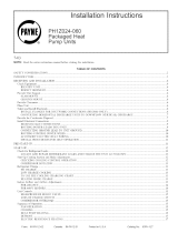
NOTES:
1. Clearances must be maintained to prevent recirculation of air from outdoor-
fan discharge.
2 Adequate clearance around air openings into combustion chamber must
be provided.
Fig. 2 -- PYIP018-042 Without Base Rail, Unit Dimensions
--2--

SLOWER ACCESS
PANEL
BURNER ANS CONTROL BOX
RIGHT _IDE VIEW ACCESS PANEL
REQ'D CLEARANCES FOR SERVICING. in. (mm)
Duct panel ............................. 0
Unit top ........................... 36 (914)
Side opposite ducts ..................... 36 (914)
Compressor access ..................... 36 (914)
(Except for NEC requirements)
REQ'D CLEARANCES TO COMBUSTIBLE MAT'L. in (ram)
Maximum extension of overhangs ............... 48 (1219)
Unit top ........................... 14 (356)
Duct side of unit ........................ 2 (51)
Side opposite ducts ..................... 14 (356)
Bottom of unit ........................... 0
Ftue panel ......................... 36 (914)
NEC REQ'D CLEARANCES. in. (ram)
Between units, control box side ................ 42 (1067)
Unit and ungrounded surfaces, control box side ......... 36 (914)
Unit and block or concrete walls and other grounded
surfaces, control box side .................. 42 (1067)
7/8" (22,2) OIA. I I/8" (28.6) GIA,
C(:_ITROL ENTRY POWER ENTRY
1A_/B:TR(41.3) OI A. /
I/2" - 14 NPT FLUE PANEL
GAS CONNECTION
REARVIEW
FLUE HOOD
K
18 I/
(458
(142.
F
1 S/It
(29,S) (253.8)
o
1 9/16"
52"
(1320_8)
A/
-45 I/2"
COND COIL (115E,7)
43 11/16 °
(II08.B)
3 5/1G_
(84,1) I
1 1/4"
(31,75)
ALTERNATE POWER ENTRY
EVAP COIL ACCESS
OPTIONAL RETURN
/ AIROPENING
/
7"
(368.9)
T
(52. S)
GUPPLY 10 9/16"
(268, 9)
_1 11/16" (48,2)
(43.21
-OPTIONALSUPRLY
AIR OPENING
COMPRESSOR ACCESS PANEL
(325.4)
1 3/4 ° NPT (19.0)
(34,S) SRAIN OUTLET
LEFT SIDE VIEW 2 3/16" FRONT VIEW
(SS.6)
UNIT
PYIP018040
PYIP024040
PYIP024060
PYIP030040
PYIP030060/080
PYIP036060/080
PYIP036100/120
PYIP042060/080
PYIP042100/120
ELECTRICAL
CHARACTERISTICS
208/230-1-60
208/230-1-60
208/230-1-60
208/230-1-60, 208/230-3-60
208/230-1-60, 208/230-3-60
208/230-1-60, 208/230-3-60, 460-3-60
208/230-1-60, 208/230-3-60, 460-3-60
208/230-1-60, 208/230-3-60, 460-3-60
208/230-1-60, 208/230-3-60, 460-3-60
UNIT WEIGHT
Ib kg
296 135
327 149
339 155
344 157
356 162
360 164
372 169
399 181
411 187
CORNER WEIGHT UNIT HEIGHT
(Ib/kg) (in,/rnm)
A B C D E
87/40 68/31 82/37 59/27 274/697
103/47 49/22 129/59 46/21 274/697
106/48 52/24 132/60 49/22 274/697
106/48 53/24 132/60 53/24 274/697
102/46 71/32 123/56 60/27 274/697
92/42 82/37 117/53 69/31 274/697
95/43 85/39 120/55 72/33 274/697
101/46 92/42 125/57 81/37 31.4/798
104/47 95/43 128/58 84/38 31.4/798
UNIT
PYIP018040
PY1P024040
PY1P024060
PY1P030040
PY1P030060/080
PY1P036060/080
PY1P036100/120
PYIP042060/080
PY1P042100/120
F G
in./mm in./mm
19%/5048 22¼/5654
23%/6064 26¼/6668
CENTER OF GRAVITY in./mm
X
25.04/636
26.90/683.3
26.82/681.2
26.57/674.9
26.93/684
27.31/693.7
27.23/691.6
26.87/682.5
26.81/681
Y Z
2272/577
2017/5123
2022/5136
201 /5093 13.16/334.3
211 /5354
210 /5326
210 /5331
210 /5331
14.96/380
210 /5337
LEGEND
CG -- Center of Gravity MAT'L -- Material
COND -- Condenser NEC -- NationaI Electrical Code
LV -- Low Voltage REQ'D -- Required
NOTES:
1 Clearances must be maintained to prevent recirculation of air from outdoor-
fan discharge
2. Adequate clearance around air openings into combustion chamber must
be provided
Fig. 3 -- PYIP018-042 With Optional Base Rail, Unit Dimensions
--3--

(19,0)
(55,B) DRAIN OUTLET
FRONT VIEW
RETURN
AIR OPENING
14 71IS"
(365.91
l _'2 1/lS"
(52,6)
10 9/16 °
(268,9)
FLUE HOOD
18 1/16
(458,8)
(E8,0)
t 3116 _
129.GI
0 7/8" (22.23) 1 1/4" (31.?51
ALTERNATELV ENTRY ALTERNATEPOWERENTRY
EVAPCOIL ACCESg
(292. I ) 1325.4) (36, 3)
(253,81
LEFTSIDE VIEW
REQ'D CLEARANCES FOR SERVICING. in (ram)
Duct panel ............................. 0
Unit top ........................... 36 (914)
Side opposite ducts ..................... 36 (914)
Compressor access ..................... 36 (914)
(Except for NEC requirements)
REQ'D CLEARANCES TO COMBUSTIBLE MAT'L. in (ram)
Maximum extension of overhangs ............... 48 (1219)
Unit top ........................... 14 (356)
Duct side of unit ........................ 2 (51)
Side opposite ducts ..................... 14 (356)
Bottom of unit ........................... 0
Flue panel ......................... 36 (914)
NEC REQ'D CLEARANCES. in (ram)
Between units, control box side ................ 42 (1067)
Unit and ungrounded surfaces, control box side ......... 36 (914)
Unit and block or concrete walls and other grounded
surfaces, control box side .................. 42 (1867)
718" (22.2)DIA, I I18" (28.6)OIA.
CONTROLENTRY POWERENTRY
28 15/16
1734 ' I I
1 5/9" (41.9) OIA, _-_
GAS ENTRY
I/2"- 14 NPT
GASOONNECT!0N
i
FLUE PANEL
UNIT
ELECTRICAL
CHARACTERISTICS
PY1PO48080 208/230-1-60, 208/230-3-60,460-3-60
PY1P048100/120/140 208/230-1-60, 208/230-3-60,460-3-80
PY1P060080 208/230-1-60, 208/230-3-60,460-3-80
PYIP060100/120/140 208/230-1-60, 208/230-3-60,460-3-80
UNIT
PYIP048080
PYIP048100/120/140
PYIP060O80
PYIP060100/120/140
CENTER OF GRAVITY (in./mm)
UNIT WEIGHT
Ib kg
414 188
426 193
453 206
465 211
A
107/49
110/50
117/53
120/55
CORNER WEIGHT
(Ib/kg)
B C
83/38 158/72
86/39 159/72
93/42 167/76
96/44 167/76
LEGEND
CG -- Center of Gravity MAT'L -- MateriaI
X Y
28.76/731 2346/596
28.42/722 2342/595
28.36/720 2327/591
27.95/710 2323/590
D
66/30
71/32
76/35
82/37
Z
1535/390
1535/390
1535/390
1535/390
COND -- Condenser NEC -- National Electrical Code
LV -- Low Voltage REQ'D -- Required
NOTES:
1. Clearances must be maintained to prevent recircutation of air from outdoor-
fan discharge.
2 Adequate clearance around air openings into combustion chamber must
be provided.
Fig. 4 -- PYIP048,060 Without Base Rail, Unit Dimensions
--4--

GIG"
(23, B)
+45 1/2"
CON0 C0IL (115B,71
/
43 11/16"
1110B.8)
(281,4)
(433+a1
AIR OPENING
14 ?/16"
(355.9)
1,
t L2 1116"
(52,6)
10 BilE"
(268.91
5/B"
:39B,91
BLOWER ACCESS BURNER ANO CONTROL BOX
PANEL RIGHT SIDE VIEW ACCESS PANEL
ACCESB PANEL
13/15"
3/4" NPT {15.0)
DRAIN OUTLET
J 3115"
(55,B1 FRONT VIEW
FLUE HO00
1B 1/15
(458.8)
L__
B 518"
(142.9)
r-
1B/16: _lO "_
(29.5) (253.5)
I 114"
(31,7G3
ALTERNATE POWER ENTRY
EVAP COIL ACCEBB
\,
\
\
/16"
REQ'D CLEARANCES FOR SERVICING. in. (ram)
Duct panel ............................. 0
Unit top ........................... 36 (914)
Side opposite ducts ..................... 36 (914)
Compressor access ..................... 36 (914)
(Except for NEC requirements)
REQ'D CLEARANCES TO COMBUSTIBLE MAT'L. in (ram)
Maximum extension of overhangs ............... 48 (1219)
Unit top ........................... 14 (356)
Duct side of unit ........................ 2 (51)
Side opposite ducts ..................... 14 (356)
Bottom of unit ........................... 0
Flue panel ......................... 36 (914)
NEC REQ'D CLEARANCES. in. (ram)
Between units, controt box side ................ 42 (1867)
Unit and ungrounded surfaces, control box side ......... 36 (914)
Unit and block or concrete walls and other grounded
surfaces, control box side .................. 42 (1067)
2 1116"
(G2.3) _
?%Nf&2 NT ¢7
1 13116'
29 7/8"
32 1/4" (287.3)
,8,B.B)I
4_I t18" (2B.G) OIA+
POWER ENTRY
to
, /
1 B/B" (41=31 OIA.
GAS ENTRY
I/2" - 14 NPT FLUE PANEL
GAS CONNECTION
UNIT
ELECTRICAL
CHARACTERISTICS
PYIP048080 208/230-1-60,208/230-3-60,460-3-60
PY1P048100/120/140 208/230-1-60,208/230-3-60,460-3-60
PYIP060OBO 208/230-1-60,208/230-3-60,460-3-60
PYIP060100/120/140 208/230-1-60,208/230-3-60,460-3-60
UNIT WEIGHT
Ib kg
438 199
450 205
477 217
489 222
A
113/51
116/53
123/56
126/57
CORNER WEIGHT
(Ib/kg)
B C
89/40 164/75
92/42 165/75
99/45 173/79
182/46 173/79
D
72/33
77/35
82/37
88/40
UNIT
PY1P048080
PY1P048100/120/140
PY1P060080
PY1P060100/120/140
CENTER OF GRAVITY (in./mm)
X Y Z
28.54/7249 2000/508 1766/4486
28.22/7168 2005/5093 1766/4486
28.18/7156 2019/5128 1766/4486
27.79/7059 2023/5138 1766/4486
LEGEND
CG -- Center of Gravity MAT'L -- Material
COND -- Condenser NEE -- National Electrical Code
LV -- Low Voltage REQ'D -- Required
NOTES:
1.Clearances must be mahTtained to prevent redrculation of air from outdoor-
fan discharge
2. Adequate clearance around air openings into combustion chamber must
be provided.
Fig. 5 -- PYIP048,060 With Optional Base Rail, Unit Dimensions
--5--

RECEIVING AND INSTALLATION
I. STEP 1 -- CHECK EQUIPMENT
A. Identify Unit
The unit model nmnber and serial number are stamped on
unit identification plate. Check this information against ship
ping papers and job data.
B. Inspect Shipment
Inspect for" shipping damage while unit is still on shipping
pallet. If unit appears to be damaged or is torn loose fl'om its
anchorage, have it examined by transportation inspectors be-
fore removal. Fm_vard claim papers directly to transporta-
tion company. Manufacturer is not responsible for any darn
age incnrred in transit.
Check all items against shipping list. hnmediately notify your
representative if any item is missing.
To prevent loss or damage, leave all parts in original pack
ages until installation.
II. STEP 2 -- PROVIDE UNIT SUPPORT
A. Roof Curb
Install accessory roof curb in accordance with instructions
shipped with curb. See Fig. 6 for roof curb dimensions. In
stall insulation, cant strips, roofing, attd flashing. Ductwork
must be attached to curb.
IMPORTANT: The gasketing of the unit to the roof curb is
critical for a watertight seal. Install gasketing material sup-
plied with the roof curb. hnproperly applied gasketing can
also result in air leaks and poor" unit performance.
Curb should be level to within 1/4inch. This is necessa W for
unit drain to flmction properly. Refer to accessory roof curb
installation instructions for additional information as
required.
B. Slab Mount
Place the unit on a solid, level concrete pad that is a mini
mmn of 4 in. thick with 2 in. above grade. The slab should be
flush on the front of the unit (to allow condensate drain in-
stallation) and should extend 2 in. on the three remaining
sides of the unit. See Fig. 7. Install a 6tin. gravel apron in
fl'ont of condenser air inlets to prevent obstrtiction of airflow
by grass or shrubs. Do not secure the unit to the slab exc'u_t
when required by local codes.
C. Flush Mount
Place side of unit with duct panel flush against transition.
On units with optional base rails, the skirt on duct-panel side
of unit cat] be removed or relocated to allow unit to be mounted
flush against transitions that extend below basepan of trait,
To move skirt, proceed as follows:
1. Remove 4 screws holding skirt to base rail. Retain screws.
2. Remove skirt or slide skirt inwards until alternate clear
ance holes align with base rails.
3. Secure with screws removed in Step 1. Holes align with
base rails.
To remove wood support under unit (with base rail only), loosen
4 screws above rigging holes and slide assembly out through
rectangular hole.
III. STEP 3 -- FIELD FABRICATE DUCTWORK
Secure all ducts to roof curb and building structure on verti-
cal discharge units. Do [rot cczmect chlctwork to unit. For hori-
zontal applications, unit is provided with flanges on the hori
zontal openings. All ductwork should be secured to the flanges.
Insulate attd weatherproof all external ductwork, joints, attd
roof openings with counter flashing and inastic in accordance
with applicable codes.
Ducts passing through an unconditioned space must be in-
sulated and covered with a vapor barrier.
If a plenmn return is used on a vertical unit, the return should
be ducted through the roof deck to comply with applicable
fire codes.
A minimum clearance is not required around ductwork. Cabi-
net return air static shall not exceed -.25 in. wg.
IV. STEP 4 -- PROVIDE CLEARANCES
The required n_inimunt operating and service clearances are
shown in Fig. 2-5. Adequate combustion, ventilation, and cot]-
denser air must be provided, in accordance with section 5.3,
Air for Combustion and Ventilation, of the National Fuel Gas
Code ANSI (American National Standards Association) Z223.1
(in Canada, sections 7.2, 7.3 or 7.4 or Can/CGA [Canadian
Gas Association] B 149 Installation Codes), or applicable pro-
visions of local building code.
The condenser fat] pushes air through the condenser coil and
discharges it through the bank of louvers in the top cover,
the decorative grille on the right side of the unit, and the con>
presser access panel. Be sure that the fan discharge does not
recirculate to the condenser coil. Do not locate the unit in ei-
ther a corner or tinder an overhead obstruction. The mini-
mum clearance under a partial overhang (such as a normal
house overhang) is 48-in. above the unit top. The maximunl
horizontal extension of a partial overhang must not exceed
48 inches.
Do not place the unit where water, ice, or snow fl'om an over-
hang or roof will damage or flood the unit. Do not install the
unit on carpeting, tile, or other combustible materials. The
unit may be installed on wood flooring or on Class A, B, or C
roof covering materials.
V. STEP 5 -- RIG AND PLACE UNIT
Use spreader bars or crate top when rigging the unit. The
units must be rigged for lifting as shown in Fig. 8 and 9. Re-
fer to Table 1 for operating weight attd to Fig. 2 5 for" corner
weights. U[se extreme c'ozlticzr to pz'eveirt ct_moge wheir mov
ing tire zmib U)rit must ['emoin in on zqJz'(ght [rositio:r dzlz'inq
oH ['{qgd/_,_ and moviz\_ OlreZ'ation.s. The unit Intist be level for
proper condensate drainage; therefore, the groundqevel pad
or accessory roof curb must be level before setting the unit it]
place. When a field fabricated support is used, be sure that
the support is level and properly supports the unit.
--6--

FLAT
CURB
PART NUMBER
CPRFCURB001A01
CPRFCURB002A01
CPRFCURB003A01
_A_
8" [203]
11" [279]
14" [356]
POWER AND
GAS ENTRY
6
"0
5UPPLY AIR
[SEE DETAIL "A "j
17!
[44E]
SUPPLY AIR
OPENING
RETURN AIR
OPENING
[279 (406]
3G 3/4".
[1010]
[13]
SCREW DLEARANOE
SEAL
(_PPLIED
WITH CURB)
FOR UNITS WITH
BASE RAILS)
(FIELD SUPPLIED)
=FING FELT
(FIELD SUPPLIED)
(FIELD SUPPLIED)
MATERIAL
(FIELD SUPPLIED)
THIS BRACKET MUST BE REMOVED
BEFORE iNSTALLATION
\
MUST BE REMOVED
BEFORE INBTALLATION
IGIO INSULATION
(FIELD SUPPLIED)
DETAIL "A"
33 7/8"
[858]
NOTES:
1. Roof curb must be set up for unit being installed.
2. SeaI strip must be applied as required for unit being installed.
3. Dimensions in [ ] are in millimeters.
4. Roof curb is made of 16 gage steel.
5. Attach ductwork to curb (flanges of duct rest on curb).
6. Service clearance 4 ft on each side.
7. [_ Direction of airflow.
8. Insulated panels: 1-in. thick fiberglass 1 Ib density.
Fig. 6 -- Roof Curb Dimensions
--7--

2,0'z,,
FLUSHWITHSLAB_ _F2. 0-
//i ! I
/ J
/ ,
/ b
// I I
/ I I
L. ...... J
, _
r "1
I I
I i
I I
I t
I t
L J
......U.......... ;_7.........20,,
CONCRETESLAB
Fig. 7 -- Slab Mounting Details
SEEDETAILA"_
SEAL STRIP MUST BE IN
PLACE BEFORE PLACING
UNIT ON ROOF CURB "1
914-1371 /
(36"- 54") /
_'_ DUCT END l\
/
SECURESCREW
AGAINSTBASEPAN
TO HOLDLIFTING
BRACKETINPLACE
DETAIL A
NOTICE TO RIGGERS
Hook rigging shackles through holes in lifting brackets, as shown in De-
tail "A." Lifting brackets to be centered around the unit center of gravity.
Use wooden top skid when rigging, to prevent rigging straps from dam-
aging unit.
UNIT MAX A B C
PYIP WEIGHT
Size Ib kg in. mm in. mm in. mm
018 332 150 24.3 618 24.85 631
024 375 170 22.4 570 24.85 631
030 384 174 22.3 585 24.85 631
036 408 185 49.4 !255 22.0 559 24.85 631
042 447 203 22.5 571 28.85 733
048 486 220 21.0 533 34.85 885
060 525 238 21.5 545 34.85 885
Fig. 8 -- Suggested Rigging for Units Without
Base Rail
!
S 4-1371 UNIT ON ROOF CURB
BEE DETAIL A
NOTICE TO RIGGERS
Hook rigging shackles through holes in lifting brackets, as shown in De-
tail "A." Lifting brackets to be centered around the unit center of gravity.
Use wood top skid when rigging, to prevent rigging straps from damag-
ing unit. Remove 4 screws to slide wood support through rectangular
hole in rail.
UNIT MAX
PYIP WEIGHT
Size Ib kg
018 320 145
024 363 165
030 380 172
036 396 180
042 435 !97
048 474 215
060 5!3 233
A
in,
49.4
mm in.
24.4
22.6
22.5
1255 22.2
22.6
2! .2
21.6
mm
619
574
571
563
574
538
549
in, mm
28.2 715
28.2 715
28.2 715
28.2 715
32.2 816
38.2 969
38.2 969
Fig. 9 -- Suggested Rigging for Units With
Optional Base Rail
A. Units Without Base Rail
If accessory rigging brackets are to be used for rigging, in-
stall them as follows:
1. Position brackets as close to the corners of unit as pos-
sible. Be sure brackets are well outside of center of grav-
ity. See Fig. 2 and 4.
2. Position paint protectors and foam strips between screws
and painted surface of unit. Tighten screws until they
make contact with the paint protectors.
3. Secure device or hook of sufficient strength to hole in
bracket as shown in detail "A" of Fig. 8.
4. If wood top is available, use it for a spreader bar to pre-
vent straps fl'om damaging unit. If wood top is not avail-
able, use spreader bars of sufficient length.
--8--

B. Units With Optional Base Rail
Lifting holes are provided in optional base rail as shown in
Fig. 9. Operating weights are shown in Table 1. Refer to rig-
ging instructions on unit.
Protective wood support must be removed from unit before
unit is mounted to curb. Remove 4 screws that secure sup
port above rigging holes in rails. Slide support out through
rectangular hole in rail. See Fig. 9.
Vl. STEP 6 -- CONNECT CONDENSATE DRAIN
NOTE: When installing condensate drain connection be sure
to comply with local codes and restrictions.
Model PY1P disposes of condensate water through a 3/4 in.
NPT fitting which exits through the compressor access panel.
See Fig. 2 5 for location.
Condensate water can be drained directly onto the roof in roof
top installations (where permitted) or onto a gravel apron in
groundqevel installations. Install a field-supplied conden-
sate trap at end of condensate connection to ensure proper
drainage. Make sure that the outlet of the trap is at least
1 in. lower than the drain pan condensate connection to pre
vent the pan fi'om overflowing. See Fig. 10. Prime the trap
with water. When using a gravel apron, make sure it slopes
away fl'om the unit.
If the installation requires draining the condensate water away
fi'om the unit, install a 2-in. trap at the condensate connec-
tion to ensure proper drainage. See Fig. 10. Make sure that
the outlet of the trap is at least 1 in. lower than the drain-
pan condensate connection to prevent the pax] fi'om overflow
ing. Prime the trap with water. Connect a drain tube using a
minimum of 3/4 in. PVC or 3/4 in. copper pipe (all field
supplied) at the outlet end of the 2-in. trap. Do not undersize
the tube. Pitch the drain tube downward at a slope of at least
one in. for every 10 ft of horizontal run. Be sure to check the
drain tube for leaks.
1" MIN,
t
Fig. 10 -- Condensate Trap
VIII, STEP 7 -- Install Flue Hood
The flue hood assembly is shipped screwed to the control box
in the burner compartment. Remove the burner access panel
to locate the assembly.
Fox" units being installed in California Air Quality Manage
ment Districts which require NO x emissions of 40 nanograms/
joule or less, kit CRLOWNOX001A00 must be installed.
Install the flue hood as follows:
1. This installation must conform with local building codes
and with the National Fuel Gas Code (NFGC), ANSI
Z223.1 (in Canada, CAN/CGA B149.1, and B149.2), or
NFPA (National Fire Protection Association) latest re
vision. Refer to Provincial and local plumbing or waste-
water codes and other" applicable local codes.
2. Remove fl'om shipping location. Place vent cap assem
bly over fine panel. Orient screw holes in vent cap with
holes in the fine panel.
3. Secure flue hood to flue panel by inserting a single screw
on the right side, the left side, and the top of the hood.
VIII. STEP 8 -- INSTALL GAS PIPING
The gas supply pipe enters the unit through the access hole
provided. The gas connection to the unit is made to the 1/d in.
FPT gas inlet on the manual shutoff or gas valve.
Install a gas supply line that runs to the heating section. Re
fer to Table 2 and the NFGC for" gas pipe sizing. Do not zl.se
ca.st iron pipe. It is recommended that a black iron pipe is
used. Check the local utility fox" recommendations concern-
ing existing lines. Size gas supply piping fox" 0.5 in. wg maxi-
mum pressure drop. Never" zLse pipe _smaller than tire _/z-hr.
FPT go_s hrlet on tire unit ga_s valve.
For natural gas applications, the gas pressure at unit gas cox]-
nection must not be less than 4.0 in. wg or greater than
13 in. wg while the unit is operating. For propane applica-
tions, the gas pressure must not be less than 4.0 in. wg or
greater than 13 in. wg at the unit connection.
An l/a-in. NPT plugged tapping accessible for test gage cox]-
nection must be installed immediately upstream of the gas
supply connection to the furnace.
When installing the gas supply line, observe local codes per
raining to gas pipe installations. Refer to the NFGC ANSI
Z223.1-1988 NFPA latest edition (in Canada, CAN/CGA B 149.1,
(2) M86). In the absence of local building codes, adhere to the
following pertinent recommendations:
1. Avoid low spots in long runs of pipe. Grade all pipe
V4 inch in every 15 ft to prevent traps. Grade all hori-
zontal runs downward to risers. Use risers to connect to
heating section and to meter.
2. Protect all segments of piping system against physical
and thermal damage. Support all piping with appropri-
ate straps, hangers, etc. Use a minimum of one hanger
every 6 ft. Fox" pipe sizes larger than _?zin., follow rec
ommendations of national codes.
3. Apply joint compound (pipe dope) sparingly and only to
male threads of joint when making pipe connections. Use
only pipe dope that is resistant to action of liquefied
petroleum gases as specified by local and/or national codes.
Newt u_se Teflon talre.
4. Install sediment trap in riser" leading to heating section
per Fig. 11. This drip leg functions as a trap for" dirt and
condensate.
5. Install an accessible, external, manual main shutoffvalve
in gas supply pipe within 6 ft of heating section.
6. Install groundOoint union close to heating section be-
tween unit manual shutoff and external manual main
shutoff valve.
7. Pressure test all gas piping in accordance with local and
national plumbing and gas codes before connecting pip-
ing to unit.
NOTE: Pressure test the gas supply system a/terthe gas sup-
ply piping is connected to the gas valve. The supply piping
must be disconnected from the gas valve during the testing
of the piping systems when test pressure is in excess of
0.5 psig. Pressure test the gas supply piping system at pres-
sures equal to or less than 0.5 psig. The unit heating section
must be isolated from the gas piping system by closing the
external main manual shutoff valve and slightly opening the
groundOoint union.
--9--

Table I -- Physical Data -- Unit PYIP
UNIT SIZE PYIP
NOMINAL CAPACITY (ton)
OPERATING WEIGHT (Ib)
Without Base Rail
With Optional Base Rail
COMPRESSORS
Quantity
REFRIGERANT (R-22)
Charge (Ib)
REFRIGERANT METERING DEVICE
Orifice ID (in,)
CONDENSER COIL
Rows,..Fins/in,
Face Area (sq ft)
CONDENSER FAN
Nominal Cfm
Diameter (in.)
Motor Hp (Rpm)
EVAPORATOR COIL
Rows Fins/in.
Face Area (sq ft)
EVAPORATOR FAN
Nominal Airflow (Cfm)
Size (in.)
FURNACE SECTION*
Burner Orifice (Qty.,.drilt size)
Natural Gas
Burner Orifice (Qty._drill size)
Propane Gas
RETURN-AIR FILTERS (in.)t
Throwaway
018040 024040 024060 030040 030060 030080 036060
11/2 2 2 2//z 2 Y, 2i/, 3
036080
3
036100
3
036120
3
272 303 315 320 332 332 336 336 348 348
296 327 339 344 356 356 360 360 372 372
Rotary Reciprocating
1 1
i
260 2.75 2.75 3.40 I 3.40 340 430 430 4.30 430
m
Acutror MDevice
.030 030 030 030 030 .030 .032 .032 032 .032
1.17 1..17 1..17 2..17 2..17 2.17 2.17
595 5.95 5.95 5.95 5.95 595 595
1700 1700 1700 1900 1900 1900 1900
18 18 18 18 18 18 18
1A(850) V_(850) V_(850) V8(850) V8(850) _A(850) ¼ (1050)
3.15 3..15 3..15 3..15 3..15 3.15 3.15
183 2.29 2.29 2.29 2.29 229 306
Direct Drive
600 800 800 1000 1000 1000 1200
10 x 10 10 x 10 10 x 10 10 x 10 10 x 10 10 x 10 10 x 10
1.32 1..32 2..32 1..32 2..32 2.32 2.32
1.41 1..41 2..47 1..41 2..47 2.42 2.47
20 x 20 20 x 20 20 x 20 20 x 24 20 x 24 20 x 24 20 x 24
2.17
595
1900
18
_(1050)
3.15
306
1200
10 x 10
2.32
2. 42
20 x 24
2..17
5.95
1900
18
1A(1050)
3..15
3.06
1200
10 x 10
2..32
2..40
20 x 24
2.17
595
1900
18
¼ (1050)
3.15
306
1200
10 x 10
3.32
3 .42
20 x 24
UNIT SIZE PYIP 042060 042080 042100 042120 048080 048100 048120 048140 060080 060100 060120 060140
NOMINAL CAPACITY (ton) 3 ½ 3½ 3 ½ 34½ 4 4 4 4 5 5 5 5
OPERATING WEIGHT (tb)
Without Base Rail 375 375 387 387 414 426 426 426 453 465 465 465
With Optional Base Rail 399 399 411 411 438 450 450 450 477 489 489 489
COMPRESSORS Reciprocating Hermetic Scroll
Quantity 1 1
REFR,GERANT(R-22,I I I I
Charge (Ib) 520 520 520 520 650 650 650 650 700 7.00 7.00 7.00
REFRIGERANT METERING Acutrot Device
DEVICE
Orifice ID (in.) .034 .034 .034 .034 .030 .030 .030 .030 .030 030 030 030
CONDENSER COIL
Rows...Fins/in. 2.17 2.17 2.17 2.17 2.17 2.17 2.17 2.17 2.17 2...17 2..17 2..17
Face Area (sq ft) 704 704 704 704 867 867 867 867 867 8.67 8.67 8.67
CONDENSER FAN
Nominal Cfm 1900 1900 1900 1900 2400 2400 2400 2400 2400 2400 2400 2400
Diameter (in.) 18 18 18 18 20 20 20 20 20 20 20 20
Motor Hp (Rpm) _¼(1050) _¼(1050) _¼(1050) _¼(1050) % (1050) % (1050) % (1050) % (1050) % (1050) _/J(1050) _/J(1050) _/J(1050)
EVAPORATOR COIL
Rows Fins/in. 3.15 3.15 3.15 3.15 3..15 3..15 3..15 3..15 4..15 4..15 4..15 4..15
Face Area (sq ft) 333 333 333 333 444 444 444 4.44 4.44 4.44 4.44 4.44
EVAPORATOR FAN Direct Drive
Nominal Airflow (Cfm) 1400 1400 1400 1400 1600 1600 1600 1600 1995 1995 1995 1995
Size (in.) 10 x 10 10 x 10 10 x 10 10 x 10 10 x 10 10 x 10 10 x 10 10 x 10 10 x 10 10 x 10 10 x 10 10 x 10
FURNACE SECTION*
Burner Orifice (Qty...drill size) 2.32 2.32 2.32 3.32 2.32 2.32 3.32 3..32 2..32 2..32 3..32 3..32
Natural Gas
Burner Orifice (Qty...drill size) 2.47 2.42 2.40 3.42 2.42 2.40 3.42 3..40 3..42 2..40 3..42 3..40
Propane Gas
RETURN-AIR FILTERS (in.)t
Throwaway 24 x 24 24 x 24 24 x 24 24 x 24 24 x 30 24 x 30 24 x 30 818"* 24 x 30 24 x 30 24 x 30 960**
*Based on altitude of 0-2000 feet.
tRequired filter sizes shown are based on the larger of the ARI (Air Conditioning & Refrigeration Institute) rated
cooling airflow or the heating airflow at a velocity of 300 ft/min for throwaway type or 450 ft/min for high-capacity
type. For non-standard air filters, air filter pressure drop must not exceed 0.08 in. wg
**Sq inch Fitter is mounted external to unit.
--]0--

A. Configuring Units for Downflow (Vertical) Discharge
8. Check for gas leaks at the field installed and factory
installed gas lines after all piping connections have been
completed. Use soap-and-water solution (or method speci-
fied by local codes and/or regulations).
IN
--]
d_..1_ TEE
/ NtPPLE
_,_ CAP
Fig. 11 -- Sediment Trap
IX. STEP 9 -- INSTALL DUCT CONNECTIONS
The unit has duct flanges on the supply and return air open
ings on the side and bottom of the unit. See Fig. 2 5 for con
nection sizes and locations.
1.
2.
Open all electrical disconnects before starting any serv
ice work.
Remove return duct covet" located on duct panel.
Figure 12 shows duct covet" removed. Save duct cover
and screws.
3. Locate lances in basepan insulation that are placed over
the perimeter of the vertical duct opening covet"
(Fig. 13).
4. Using a straight edge and sharp knife, cut and remove
the insulation around the perimeter of the cover. Re-
move and save 5 screws securing the cover to the base-
pan and slide out the covet'. Discard the cover (Fig. 14).
5. Remove supply duct covet" located on duct panel.
Figure 12 shows duct cover removed. Save duct covet"
and screws.
Remove and discard 2 screws which secure vertical dis
charge opening cover to basepan (Fig. 15). Slide covet"
forward to disengage, then tilt and remove cover through
vertical discharge opening in bottom of unit. Discard
duct covet" (Fig. 16).
7. If unit ductwork is to be attached to vertical opening
flanges on the unit basepan 0ackstand applications only),
do so at this time.
8. It is recommended that the basepan insulation around
the perimeter of the vertical return air opening be se
cured to the basepan with aluminum tape. Applicable
local codes may require aluminum tape to prevent ex-
posed fiberglass.
9. Covet" both horizontal duct openings with the duct coy
ers fi'om Steps 2 and 5. Make sure opening is air- and
watertight.
10. After completing unit conversion, perform all safety
checks and power up unit.
NOTE: The design and installation of the duct system must
be in accordance with the standards of the NFPA for instal-
lation of nonresidence-type air conditioning and ventilating
systems, NFPA 90A or residence type, NFPA 90B; and/or lo
cal codes and residence type, NFPA 90B; and/or local codes
and ordinances.
--11--

Table 2 -- Maximum Gas Flow Capacity*
NOMINAL INTERNAL LENGTH OF PIPE, FTI"
IRON PIPE, DIAMETER
SIZE
(in.) (in.) 10 20 30 40 50 60 70 80 90 100 125 150 175 200
I/2 .622 175 120 97 82 73 66 61 57 53 50 44 40 -- --
3/4 .824 360 250 200 170 15! 138 125 118 !10 103 93 84 77 72
1 1.049 680 465 375 320 285 260 240 220 205 195 175 160 145 !35
11/4 1.380 1400 950 770 600 580 530 490 460 430 400 360 325 300 280
11/2 1.610 2100 !460 1180 990 900 8!0 750 690 650 620 550 500 460 430
*Capacity of pipe in cu ft of gas per hr for gas pressure of 0.5 psig or less. Pressure drop of 0.5-in. wg (based on
a 0.60 specific gravity gas). Refer to Table C-4, National Fire Protection Association NFPA 54.
1-This length includes an ordinary number of fittings.
SUPPLY DUCT OPENING RETURN DUCT OPENING
Fig. 12 -- Supply and Return Duct Openings
Fig. 14 -- Vertical Duct Cover Removed
Fig. 13 -- Lance Location for Vertical Duct
Opening Cover
Fig. 15- Removal of Vertical Discharge
Opening Cover
--12--

-- X.STEP10 -- INSTALL ELECTRICAL CONNECTIONS
Fig. 16 -- Vertical Discharge Cover Removed
Adhere to the following criteria when selecting, sizing, and
installing the duct system:
1. Units are shipped with all 4 duct openings covered. Re-
move appropriate panels for intended installation.
2. Select and size ductwork, supply-air registers, and
return-air grilles according to American Society of
Heating, Refrigeration and Air Conditioning Engineers
(ASHRAE) recmnmendations.
3. Use flexible transition between rigid ductwork and unit
to prevent transmission of vibration. The transition may
be screwed or bolted to duct flanges. Use suitable gas
kets to ensure weathertight and airtight seal.
4. All units must have field supplied filters or accesso W fil
ter rack installed in the return air side of the unit. Rec
ommended sizes for filters are shown in Table 1.
5. Size all ductwork for maxinlmn required airflow (either
heating or cooling) for unit being installed. Avoid abrupt
duct size increases or decreases or performance may be
affected.
6. Adequately insulate and weatherproof all ductwork
located outdoors. Insulate ducts passing through uncon-
ditioned space, and use vapor barrier in accordance with
latest issue of Sheet Metal and Air Conditioning
Contractors National Association (SMACNA) and Air Con
ditioning Contractors of America (ACCA) minimum in-
stallation standards for heating and air conditioning
systems. Secure all ducts to building structure.
7. Flash, weatherproof, and vibration-isolate all openings
in building structure in accordance with local codes and
good building practices.
1. Make all electrical connections in accordance with NEC
ANSI/NFPA (latest edition) and local electrical codes gov
erning such wiring. In Canada, all electrical connec-
tions must be in accordance with CSA standard C22.1
Canadian Electrical Code Part 1and applicable local codes.
Refer to unit wiring diagram.
2. Use only coi)perconductor for connections between field
supplied electrical disconnect switch and unit. DO NOT
USE ALUMINUM WIRE.
3. Be sure that high voltage power to unit is within oper
ating voltage range indicated on unit rating plate.
4. Do not damage internal components when drilling through
any panel to mount electrical hardware, conduit, etc. On
3 phase units, ensure phases are balanced within 2%.
Consult local power company for correction of improper
voltage and/or phase imbalance.
A. High-Voltage Connections
The unit must have a separate electrical service with a field
supplied, waterproof, disconnect switch mounted at, or within
sight from, the unit. Refer to the unit rating plate for maxL
mum fllse/circuit breaker size and minimum circuit amps (am-
pacity) for" wire sizing. See Table 3 for electrical data.
The field supplied disconnect switch box may be mounted on
the unit over the high voltage inlet hole when tire standard
power and low-voltage entry points are used. See Fig. 2-5 for"
acceptable location.
Standard Power Enti T
Proceed as follows to complete the high-voltage connections
to the unit:
1. Connect ground lead to chassis ground connection when
using separate ground wire.
2. Run high-voltage leads into unit control box.
3. Locate black and yellow wires connected to line side of
contactor.
4. Cut wires at partition where they exit control box.
5. Strip back leads and connect to high voltage leads. On
3 phase units, blue wire is provided stripped back and
ready to connect to high voltage lead. See unit wiring
label and Fig. 17.
--13--

Table 3 -- Electrical Data -- Unit PYIP
UNIT VOLTAGE
SIZE V-PH-Hz RANGE
PY1P Min Max
018 208/230-1-60 187 253
024 208/230-1-60 187 253
208/230-1-60 187 253
030
208/230-3-60 187 253
208/230-1-60 187 253
036 208/230-3-60 187 253
460-3-60 4!4 506
208/230-1-60 187 253
042 208/230-3-60 187 253
460-3-60 414 506
208/230-1-601- 187 253
208/230-1-60"* 187 253
048 208/230-3-601- 187 253
208/230-3-60"* 187 253
460-3-601- 414 506
460-3-60** 4!4 506
298/230-1-60 187 253
060 208/230-3-60 187 253
460-3-60 414 506
COMPRESSOR OUTDOOR-FAN
MOTOR
RLA LRA FLA
8.3 45.0 0.7
!2.4 6! .0 0.7
14.4 82.0 1.4
9.4 66.0 1.4
18.0 96.0 1.4
11.7 75.0 1.4
5.6 40.0 0.8
20.4 104.0 1.4
14.0 9! .0 1.4
6.4 42.0 0.8
21.8 124.0 2.!
26.4 129.0 2.1
!2.8 93.0 2.!
15.0 99.0 2.1
6.4 46.5 ! .1
8.2 50.0 1.!
32.1 169.0 2.!
!9.3 123.0 2.!
19.0 62.0 ! .1
INDOOR-FAN POWER SUPPLY
MOTOR
FLA MCA MOCP*
1.8 12.9 15
2.0 18.2 30
2.3 2! .4 30
2.0 15.1 25
2.8 28.7 40
2.8 18.8 30
1.4 9.2 10
4.0 30.9 50
4.0 22.9 35
2.0 10.8 15
5.0 40.1 60
5.0 40.1 69
5.0 25.9 40
5.0 25.9 49
2.3 !3.7 29
2.3 13.7 20
6.8 49.0 60
6.8 33.0 50
3.2 !6.8 25
AWG 60 C
MIN WIRE
SIZE
14
12
10
12
10
12
14
8
10
14
8
6
10
10
!4
14
6
8
!2
MAX WIRE
LENGTH (ft)
75
8O
100
8O
9O
85
100
100
85
100
100
100
75
75
100
100
100
9O
100
LEGEND
AWG -- American Wire Gage
FLA -- Full Load Amps
HACR -- Heating, Air Conditioning and
Refrigeration
LRA -- Locked Rotor Amps
MCA -- Minimum CircuitAmps
MOCP -- Maximum Overcurrent Protection
RLA -- Rated Load Amps
*Fuse or HACR Breaker.
1-Carrier Scroll Compressor.
**CopeIand Scroll Compressor.
0Q°s
NOTES:
1. In compliance with NEC (National Electrical Code) requirements for
multimotor and combination load equipment (refer to NEC
Articles 430 and 440), the overcurrent protective device for the unit
shall be fuse or HACR breaker. The CGA (Canadian Gas Associa-
tion) units may be fuse or circuit breaker.
2. Minimum wire size is based on 60 C copper wire. If other than
60 C wire is used, or if length exceeds wire length in table, deter-
mine size from NEC.
3. Unbalanced 3-Phase Supply Voltage
Never operate a motor where a phase imbalance in supply voltage is
greater than 2%. Use the following formula to determine the percent-
age of voltage imbalance.
% Voltage imbalance
= !00 x max voltage deviation from average voltage
average voltage
Example: Supply voltage is 460-3-60.
A a C AB = 452 v
BC = 464 v
(_ AC = 455 v
Average Voltage =
452 + 464 + 455
3
= 1371
3
= 457
Determine maximum deviation from average voltage.
(AB) 457 - 452 = 5 v
(BC) 464 - 457 = 7 v
(AC) 457 - 455 = 2 v
Maximum deviation is 7 v.
Determine percent of voltage imbalance.
7
% Voltage Imbalance = 100 x --
457
= 1.53%
This amount of phase imbalance is satisfactory as it is below the maxi-
mum allowable 2%.
o
IMPORTANT: If the supply voltage phase imbalance is more than 2 Yo,
contact your local electric utility company immediately.
--14--

THERMOSTAT (TYPICAL)
1,¢o,,¢,¢91
t S J g, g
_-I _jI Z Cl I Z
z I wl rr I m I r¢l
/
2-
I SPLICE BOX
GND
LOW-VOLTAGE POWER
LEADS (SEE UNIT
WIRING LABEL)
__%K[
_-4L..U-E
]""- "_ _ '-- POWER
]_ --._q ._TI SUPPLY
----1"--S---
FIELD-SUPPLIED
FUSED DISCONNECT
LEGEND
.... Field Control-Voltage Wiring
.... Field High-Voltage Wiring
NOTE: Use blue wire for 3-phase units only.
Fig. 17 -- High- and Control-Voltage Connections
Alternate Power Entry
1. Remove knockouts in fixed compressor panel located on
duct panel side of unit.
2. Route high-voltage leads into high-voltage terminal box.
3. Connect ground wire to green yellow wire using field
supplied splice.
4. Connect power wires to unit high-voltage leads.
5. On 3 phase units, locate blue wire projecting fi'om corn
pressor junction box. Cut wire at partition and route into
high voltage junction box through grommet in back of
junction box.
6. On 3-phase units, strip back blue lead and connect to
third leg of the power wires.
B. Special Procedures for 208-v Operation
1. Disconnect the orange transformer-primary lead from
the contactor. See unit wiring label.
2. Remove the tape and wirenut fi'om the terminal on the
end of the red transformer-prhnm T lead.
3. Save the wirenut.
4. Connect the red lead to the contactor terminal fi'om which
the orange lead was disconnected.
5. Using the wirenut removed fi'om the red lead, insulate
the loose terminal on the orange lead.
6. Wrap the cover with electrical tape so that the metal
terminal cannot be seen.
C. Control Voltage Connections
Locate the roon] thermostat on an inside wall in the space to
be conditioned, where it will not be subjected to either a cool-
ing or heating source or direct exposure to sunlight. Mount
tire thermostat 4 to 5 ft above the floor.
NOTE: Do not use any type of power stealing thermostat. Unit
control problems may result.
Use no. 18 American Wire Gage (AWG) color-coded, insu-
lated (35 C mininmm) wires to make the control voltage con-
nections between the thermostat and the unit. If the thermo-
stat is located more thai] 100 ft from the unit (as measured
along the control voltage wires), use no. 16 AWG color" coded,
insulated (35 C minimum) wires.
Standard Connection
Remove knockout hole located in the flue panel adjacent to
the control access panel. See Fig. 2-5. Remove the rubber groin
met fl'om the installer's packet (included with unit) and in-
stall grommet in the knockout opening. Provide a drip loop
before running wire through panel.
Run the low voltage leads from the thermostat, through the
inlet hole, and into unit low-voltage splice box.
Locate five 18-gage wires leaving control box. These low-
voltage connection leads can be identified by the colors red,
green, yellow, brown, and white. (See Fig. 17.) Ensure the leads
are long enough to be routed into the low-voltage splice box
(located below right side of control box). Stripped yellow wire
is located in connection box. Route leads through hole in bot-
tom of control box and make low voltage connections as shown
in Fig. 17. Secure all cut wires, so that they do not interfere
with operation of unit.
Alternate Connection
Remove knockout in compressor fixed panel located below high
voltage knockout. Remove the rubber grommet fl'om the in
staller's packet (included with unit) and install grommet in
the knockout opening. Route thermostat wires through grom-
met providing drip loop at panel, Connect low voltage leads
as shown in Fig. 17.
D. Heat Anticipator Setting
The rooin thei'nmstat heat anticipator nmst be properly ad-
justed to ensure proper heating performance. Set the heat
anticipator, using an ammeter between the W and R termi
nals to determine the exact required setting.
NOTE: For thermostat selection purposes, use 0.18 amp for"
the approximate required setting.
Failure to make a proper heat anticipator adjustment will
result in improper operation, discomfort to the occupants of
the conditioned space, and inefficient energy utilization; how-
ever, the required setting may be changed slightly to provide
a greater degree of comfort for a particular installation.
E. Transformer Protection
The unit transformer protection may be one of 2 types.
The ill-st t,"on_sfoFmez"(ype may contain an auto. reset over
current protector for control circuit protection. If this device
trips, it may reset without warning, starting the heating or
cooling section of this product. Use caution when servicing; if
overcurrent protector continues to trip, there is a problem in
the low voltage electrical circuit, such as an electrical short,
ground, or transformer overload. Disconnect power, correct
the condition, and check for normal unit operation.
The _seconct rfon_stbrmel" type is of the energy limiting type. It
is set to withstand a 30 second overload or shorted second
ary condition.
--15--

PRE-START-UP
Proceed as follows to inspect and prepare the unit for initial
start up:
1. Remove all access panels.
2. Read and follow instructions on all WARNING, CAU-
TION, and INFORMATION labels attached to, or shipped
with, unit.
3. Make the following inspections:
a. Inspect for shipping and handling dan]ages such as
broken lines, loose parts, disconnected wires, etc.
b. Inspect for oil at all refi'igerant tubing connections
and on unit base. Detecting oil generally indicates a
refi'igerant leak. Leak-test all refrigerant tubing con
nections using electronic leak detector, halide torch,
or liquid soap solution. If a refi'igerant leak is de-
tected, see Check for Refi'igerant Leaks section on
this page.
c. Inspect all field and factm T wiring connections. [3e
sure that connections are completed and tight.
d. Inspect coilfins. Ifdamaged during shipping and han-
dling, carefiflly straighten fins with a fin comb.
4. Verify the following conditions:
a. Before lighting the unit for the first time, perform
the following: If the gas supply pipe was not purged
before connecting the unit, it will be full of air. It is
recommended that the ground joint union be loos-
ened, and the supply line be allowed to purge until
the odor of gas is detected. Never purge gas lines into
a combustion chamber, hnmediately upon detection
of gas odor, retighten the union. Allow 5 minutes to
elapse, then light unit.
b. Make sure that condenser-fan blade is correctly po-
sitioned in fan orifice. Leading edge of condenser fan
blade should be '/z in. maximum fl'om plastic fan ori
rice (see Fig. 18).
c. Make sure that air filter(s) is in place.
d. Make sure that condensate drain trap is filled with
water to ensure proper drainage.
e. Make sure that all tools and miscellaneous loose parts
have been removed.
_i_ -,-1/2 IN, MAX
\l
]_ / MOTOR SHAFT
Fig. 18 -- Fan Blade Clearance
START-UP
I. CHECK FOR REFRIGERANT LEAKS
Proceed as follows to locate and repair a refrigerant leak and
to charge the unit:
f. Locate leak and make sure that refrigerant system pres-
sure has been relieved and reclaimed fi'om both high
and low pressure ports.
2. Repair leak following accepted practices.
NOTE: Install a filter drier whenever the system has been
opened for repair.
3. Add a small charge of R 22 refi'igerant vapor to system
and leak test unit.
4. Evacuate and reclaim refrigerant from refrigerant sys-
tem if additional leaks are not found.
5. Charge unit with R-22 refi'igerant, using a volumetric
charging cylinder or accurate scale. Re[ki" to tlnit Foth\q
piote [bF r'_quiF_(t c'hofge. Be sure to add extra refriger-
ant to compensate for internal volume of filter drier.
--16--

II. START UP HEATING SECTION AND MAKE
ADJUSTMENTS
Do not jumper any safety devices when operating the unit.
Make sure that burner orifices are properly aligned. Un
stable operation may occur when the burner orifices in the
manifold are misaligned.
Follow the lighting instructions on the heating section opera
tion label (located inside the burner or blower access door) to
start the heating section.
NOTE: Make sure that gas supply has been purged, and that
all gas piping has been checked for leaks.
A. Check Heating Control
Start and check the unit for proper heating control operation
as follows. (See furnace lighting instructions located inside
burner or blower access panel.)
1. Place the room thermostat SYSTEM switch in the HEAT
position and the fan switch in the AUTO. position.
2. Set the heating temperature control of the thermostat
above rooIn temperature.
3. The induced-draft motor will start.
4. After a call for heating, the main burner should light
within 5 seconds. If the burners do not light, there is a
22 second delay before another 5 second try. If the burn-
ers still do not light, this sequence is repeated. If the
burners do not light within 15 minutes from the initial
call for heat, there is a lockout. To reset the control, break
the 24 v power to W.
5. The evaporator fan will turn on 45 seconds after the flame
has been established. The evaporator fan will turn off
45 seconds after the thermostat has been satisfied.
B. Check Gas Input
Check gas input and manifold pressure after unit start-up
(see Table 4). If adjustment is required proceed as follows.
The rated gas inputs shown in Table 4 are for altitudes from
sea level to 2000 ft above sea level. These inputs are based
on natural gas with a heating value of 1050 Btu/ft :_ at 0.65
specific gravity, or propane gas with a heating value of
2500 Btu/ft :_ at 1.5 specific gravity. For elevations above
2000 ft, reduce input 4% for each 1000 ft above sea level. When
the gas supply being used has a different heating value or
specific gravity, refer to national and local codes, or contact
your distributor to determine the required orifice size.
C. Adjust Gas Input
The gas input to the unit is determined by measuring the
gas flow at the meter or by measuring the manifold pressure.
Measuring the gas flow at the meter is recommended for natu-
ral gas units. The manifold pressure must be measured to
determine the input of propane gas units.
Measure Gas Flow (Natural Gas Units)
Minor adjustment to the gas flow can be made by changing
the manifold pressure. The manifold pressure must be main
rained between 3.4 and 3.6 in. wg. If larger adjustments are
required, change main burner orifices following the recom
mendations of national and local codes.
NOTE: All other appliances that use the same meter must
be turned off when gas flow is measured at the meter.
Proceed as follows:
1. Turn off gas supply to unit.
2. Remove pipe plug on manifold (see Fig. 19), then con-
nect manometer at this point. Turn on gas to unit.
3. Record number of seconds for gas meter test dial to make
one revolution.
4. Divide number of seconds in Step 3 into 3600 (number
of seconds in one hour).
5. Multiply result of Step 4 by the number of cuft shown
for one revolution of test dial to obtain cuft of gas flow
per hour.
6. Multiply result of Step 5 by Btu heating value of gas to
obtain total measured input in Btuh. Compare this value
with heating input shown in Table 4. Consult the local
gas supplier if the heating value of gas is not known.
EXAMPLE: Assume that the size of test dial is 1 cuft, one
revolution takes 30 seconds, and the heating value of the gas
is 1050 Btu/ft:L Proceed as follows:
1. 30 seconds to complete one revolution.
2. 3600 + 30 = 120.
3. 120 x 1 = 120 ft:*of gas flow/hr.
4. 120 x 1050 = 126,000 Btuh input.
If the desired gas input is 120,000 Btuh, only a minor change
in the manifold pressure is required.
Observe manifold pressure and proceed as follows to adjust
gas input:
1. Remove covet" screw over regulator adjustment screw on
gas valve.
2. Turn regulator adjustment screw clockwise to increase
gas input, or turn regulator adjustment screw counter
clockwise to decrease input. Manifold pressure must be
between 3.4 and 3.6 in. wg.
3. Replace cover screw cap on gas valve.
4. Turn off gas supply to unit. Remove manometer from
pressure tap and replace pipe plug on gas valve. Turn
on gas to unit and check for leaks.
--17--

Table 4 -- Rated Gas Inputs at Indicated Manifold Pressures
UNIT PY1 P
018040, 024040, 030040
024060, 030060, 036060, 042060
030080, 036080, 042080,
048080, 060080
036100, 042100, 048100, 060100
036120, 042120, 048120, 060120
048140, 060140
NUMBER
OF
ORIFICES
1
2
2
2
3
3
GAS SUPPLY PRESSURE
(in. wg)
Natural Propane
Min Max Min Max
4.0 13.0 4.0 !3.0
4.0 13.0 4.0 !3.0
4.0 13.0 4.0 !3.0
4.0 13.0 4.0 !3.0
4.0 13.0 4.0 13.0
4.0 13.0 4.0 !3.0
MANIFOLD
NATURAL GAS PROPANE*
PRESSURE
(in, wg)
Natural Propane
3.5 3.1
3.5 3.3
3.5 3.4
3.5 3.7
3.5 3.5
3.5 3.4
Orifice Heating
Drill Input
Size (Btuh)t
32 40,000
32 58,000
32 80,000
32 95,000
32 120,000
32 138,000
Orifice
Drill
Size
41
47
42
4O
42
4O
Heating
Input
(Btuh)t
40,000
54,000
80,000
95,000
115,000
!33,000
*When a unit is converted to propane, different size orifices must be used. See separate natural-to-propane conversion kit
instructions.
1-Based on altitudes from sea level to 2000 ft above sea level. For altitudes above 2000 ft, reduce input rating 4% for each
additional 1000 ft above sea level. In Canada, from 2000 ft above sea level to 4500 ft above sea level, derate the unit
10%.
MANIFOLD PIPE PLUG
Fig. 19- Burner Assembly
Measure Manifold Pressure (Propane Units)
The main burner orifices on a propane gas unit are sized for
the unit rated input when the manifold pressure reading
matches tire level specified in Table 4.
Proceed as follows to adjust gas input on a propane gas unit:
1. Turn off gas to unit.
2. Remove pipe plug on manifold (see Fig. 19), then con
nect manometer at this point.
3. Turn on gas to unit.
4. Remove cover screw over regulator adjustment screw on
gas valve.
5. Adjust regulator adjustment screw to the correct mani
fold pressure, as specified in Table 4. Turn adjusting
screw clockwise to increase manifold pressure, or turn
adjusting screw counterclockwise to decrease manifold
pressure.
6. Replace cover screw.
7. Turn off gas to unit. Remove manometer fl'om pressure
tap. Replace pipe plug on gas valve, then turn on gas to
unit. Check for leaks.
D. Check Burner Flame
With burner access panel removed, observe tire unit heating
operation. Watch the burner flames to see if they are light
blue and soft in appearance, and that the flames are approxi-
mately tire same for each burner. Propane will have blue flame
with yellow tips. See Fig. 20. Refer to Maintenance section
for" information on burner removal.
E. Airflow and Temperature Rise
The heating section for" each size unit is designed and ap
proved for heating operation within the temperature-rise range
stamped on the unit rating plate.
Table 5 shows the approved temperature rise range for each
heating input, and the air delivery cfln at various tempera
ture rises. The heating operation airflow must produce a tem-
perature rise that falls within the approved range.
Refer" to Evaporator Airflow and Airflow Adjustments section
on page 24 to adjust heating airflow when required.
--18--

Table 5 -- Air Delivery (Cfm) at Indicated Temperature Rise and Rated Heating Input
HEATING TEMPERATURE RISE °F
INPUT
(Btuh) 20 25 30 35 40 45 50 55 60 65 70 75 80 85 90
40,000 1389 1111 926 794 694 617 556 ........
56,000 2083 1667 1389 1190 1042 926 833 758 .......
80,000 2778 2222 1852 1587 1389 1235 1111 1010 926 855 794 ....
95,000 3472 2778 2315 1984 1736 1543 1389 1263 1157 1068 992 926 868 -- --
120,000 4167 3333 2778 2381 2083 !852 1667 1515 1389 1282 1190 1111 1042 980 928
136,000 5037 4029 3358 2878 25!8 2238 20!4 1831 1679 1549 1439 1343 !259 1185 !119
NOTE: Dashed areas do not fall within the approved temperature rise range of the unit.
P
BURNERFLAME
°°
Fig. 20 -- Monoport Burners
F. Heating Sequence of Operation
See Fig. 21-23 and unit wiring label.
On a call for heating, terminal "W" of the thermostat is en-
ergized, starting the induced draft motor. When the hall
effect sensor on the induced draft motor senses that it has
reached the required speed, the burner sequence begins. This
flmction is performed by the integrated gas control (IGC). The
evaporator-fan motor is energized 45 seconds after flame is
established. When the thermostat is satisfied and "W" is deen
ergized, tire burners stop firing and the evaporator fan motor
shuts off after" a 45 second time off delay.
A LED (light-emitting diode) indicator is provided on the con-
trol board to monitor operation. The control board is located
by removing the burner access panel. During normal opera
tion, the LED is continuously on. See Table 6 for error codes.
Table 6 -- LED Indications
ERROR CODE LED INDICATION
Normal Operation On
Hardware Failure Off
Fan On/Off Delay Modified 1 Flash
Limit Switch Fault 2 Flashes
Flame Sense Fault 3 Flashes
Four Consecutive Limit Switch Faults 4 Flashes
Ignition Lockout Fault 5 Flashes
Induced-Draft Motor Fault 8 Flashes
RolIout Switch Fault 7 Flashes
Internal Control Fault 8 Flashes
NOTES:
1. There is a 3-second pause between error code displays.
2. If more than one error code exists, all applicable error codes will be
displayed in numerical sequence.
3. This chart is on the wiring diagram located inside the burner access
panel.
G. Limit Switches
Normally-closed limit switch (LS) completes the control cir-
cuit through the thermostat R circuit. Should the leaving-air
temperature rise above the maximum allowable tempera-
ture, the limit switch opens and the R control circuit "breaks."
Any interruption in the R control circuit instantly closes the
gas valve and stops gas flow to the burners and pilot. The
blower motor continues to run until LS resets.
When the air temperature at the limit switch drops to the
low-temperature setting of the limit switch, the switch closes
and completes tire R control circuit. The electric-spark igni
tion system cycles and the unit returns to normal heating
operation.
H. Auxiliary Limit Switch -- Rollout
The function of the switch is to close the main gas valve in
the event of flame rollout. The switch is located above the
main burners. When the temperature at the auxiliary switch
reaches the maximum allowable temperatm'e, the R control
circuit trips, closing the gas valve and stopping gas flow to
the burners. The indoor (evaporator) fan motor (IFM) and in
duced draft motor continue to run tmtil switch is reset.
--19--

III. START UP COOLING SECTION AND MAKE
ADJUSTMENTS
A superheat charging label is attached to the inside of the
compressor access door. The label includes a "Superheat Charg-
ing Table" and a "Required Suction-Tube (F) Temperature"
chart.
An accurate superheat, thermocouple, or thermistor type ther
monmter, a sling psychrometer, and a gage manifold are re
quired when using the superheat charging method for evalu
ating the unit charge. Do not u,se me['c'rHy or small Hial-(ype
themlome_ers bec'ouse they ore not oclequa_e _bz"this _ype of
measzmemenb
A. Checking Cooling Control Operation
Start and check the unit for" proper cooling control operation
as follows:
1. Place room thermostat SYSTEM switch in OFF posL
tion. Observe that blower motor starts when FAN switch
is placed in ON position and shuts down when FAN switch
is placed in AUTO, position.
2. Place SYSTEM switch in COOL position and FAN switch
in AUTO. position. Set cooling control below room tem-
perature. Obsexwe that compressor, condenser fan, and
evaporator blower motors start. Observe that cooling
cycle shuts down when control setting is satisfied. The
evaporator fan will continue to run for" 30 seconds.
3. When using an auto. changeover room thermostat, place
both SYSTEM and FAN switches in AUTO. positions.
Observe that unit operates in heating mode when tern
perature control is set to "call for heating" (above room
temperature) and operates in cooling mode when tem-
perature control is set to "call for" cooling" (below room
temperature).
IMPORTANT: Three phase, scroll compressor units (sizes
048,060) are direction-oriented. These units must be checked
to ensure proper compressor 3-phase power lead orientation.
If not corrected within 5 minutes, the internal protector will
shut off the compressor. The 3 phase power leads to the unit
must be reversed to correct rotation. When turning back
wards, scroll compressors emit elevated noise levels, and the
difference between compressor suction and discharge pres-
sures may be dramatically lower than normal.
B. Checking and Adjustment Refrigerant Charge
The refrigerant system is fully charged with R-22 refriger-
ant, tested, and factory sealed.
NOTE: Adjustment of the refl'igerant charge is not required
unless the unit is suspected of not having the proper" R-22
charge.
Proceed as follows:
1. Remove caps fl'om low and high pressure service
fittings.
2. Using hoses with valve core depressors, attach low- and
high-pressure gage hoses to low- and high-pressure serw
ice fittings, respectively.
3. Start unit in cooling mode and let unit run until system
pressures stabilize.
4. Measure and record the following:
a. Outdoor ambient air temperature (F db).
b. Evaporator inlet-air temperature (F wb).
c. Suction tube temperature (F) at low side service
fitting.
d. Suction (low-side) pressure (psig).
5. Using "Superheat Charging Table," compare the out-
door entering air temperature with indoor air tempera-
rare to determine desired system operating superheat
temperature. See Tables 7A 7H.
6. Using "Required Suction-Tube (F) Temperature" table,
compare desired superheat temperature with suction (lmw
side) operating pressure (psig) to determine proper suction-
tube temperature. See Table 8.
7. Compare actual suction-tube temperature with proper
suction-tube temperature. Using a tolerance of _+3° F,
add refl'igerant if actual temperature is more than 3° F
higher than proper suction tube temperature, or re
move refrigerant if actual temperature is more than
3° F lower than required suction-tube temperature.
NOTE: If the problem causing the inaccurate readings is a
refl'igerant leak, refer to Check for"Refl'igerant Leaks section
on page 16.
2O
/