Page is loading ...

Installation Instructions
NOTE: Read the entire instruction manual before starting the
installation.
TABLE OF CONTENTS
PAGE
SAFETY CONSIDERATIONS ......................... 2
INTRODUCTION ................................... 2
RECEIVING AND INSTALLATION .................. 2-7
Check Equipment .................................. 2
Identify Unit .................................... 2
Inspect Shipment ................................. 2
Provide Unit Support ............................... 2
Slab Mount ..................................... 2
Ground Mount .................................. 2
Provide Clearances ................................. 2
Place Unit ........................................ 2
Select and Install Ductwork ........................... 2
Configuring Units for Downflow (Vertical) Discharge .... 3
Connect Condensate Drain ........................... 3
Install Electrical Connections ......................... 6
High-Voltage Connections ......................... 6
Routing Power Leads Into Unit ...................... 6
Connecting Ground Lead to Unit Ground .............. 6
Routing Control Power Wires ...................... 6
Accessory Electric Heat Wiring ...................... 6
PRE-START-UP .................................... 7
START-UP ...................................... 8-17
Check for Refrigerant Leaks .......................... 8
Start-Up Cooling and Make Adjustments ................ 8
Checking Cooling and Heating Control Operation ....... 8
Refrigerant Charge ................................. 8
No Charge ...................................... 8
Low Charge Cooling .............................. 8
Heating Mode Charge ............................. 8
Indoor Airflow and Airflow Adjustments ................ 9
Unit Controls ..................................... 9
High-Pressure Relief Valve ......................... 9
Loss-of-Charge Switch ........................... 9
Compressor Overload ............................ 10
Compressor Rotation ............................... 10
Sequence of Operation ............................. 10
Fan Operation .................................. 10
A05194
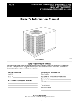
Fig. 1 - Unit PH3Z
Cooling Operation ............................ 10, 17
Heating Operation ............................... 17
Continuous Fan ................................. 17
Defrost ....................................... 17
Electric Resistance Heating ........................ 17
MAINTENANCE ................................ 17-20
Air Filter ........................................ 18
Unit Top Removal ................................. 18
Indoor Blower and Motor ........................... 18
Outdoor Coil, Indoor Coil, and Condensate Drain Pan ..... 19
Outdoor Fan ..................................... 19
Electrical Controls and Wiring ....................... 19
Refrigerant Circuit ................................. 20
Indoor Airflow ................................... 20
Metering Devices ................................. 20
Liquid Line Strainers ............................... 20
High Flow Valves ................................. 20
TROUBLESHOOTING .............................. 20
START-UP CHECKLIST ............................ 20

SAFETY CONSIDERATIONS
Installation and servicing of this equipment can be hazardous due
to mechanical and electrical components. Only trained and
qualified personnel should install, repair, or service this equipment.
Untrained personnel can perform basic maintenance functions such
as cleaning and replacing air filters. All other operations must be
performed by trained service personnel. When working on this
equipment, observe precautions in the literature, on tags, and on
labels attached to or shipped with the unit and other safety
precautions that may apply.
Follow all safety codes. Installation must be in compliance with
local and national building codes. Wear safety glasses, protective
clothing, and work gloves. Have fire extinguisher available. Read
these instructions thoroughly and follow all warnings or cautions
included in literature and attached to the unit.
Recognize safety information. This is the safety-alert symbol Z_
When you see this symbol on the unit and in instructions or manu-
als, be alert to the potential for personal iniury. Understand these
signal words: DANGER, WARNING, and CAUTION. These
words are used with the safety-alert symbol. DANGER identifies
the most serious hazards which will result in severe personal iniury
or death. WARNING signifies hazards which could result in per-
sonal iniury or death. CAUTION is used to identify unsafe practic-
es which may result in minor personal injury or product and prop-
erty damage. NOTE is used to highlight suggestions which will
result in enhanced installation, reliability, or operation.
ELECTRICALSHOCK HAZARD
Failure to follow this warning could result in personal
iniury or death.
Before installing or servicing system, always turn off main
power to system and tag. There may be more than one
disconnect switch. Turn off accessory heater power switch if
applicable.
CUT HAZARD
Failure to follow this caution may result in personal iniury.
Sheet metal parts may have sharp edges or burrs. Use care
and wear appropriate clothing.
INTRODUCTION
The PH3Z packaged heat pump is fully self-contained and
designed for outdoor installation (See Fig. 1). Standard units are
shipped in a horizontal-discharge configuration for installation on
a ground-level slab or directly on the ground if local codes permit.
Standard units can be converted to downflow (vertical) discharge
configurations for rooftop applications with a field supplied
plenum.
RECEIVING AND INSTALLATION
Step 1 -- Check Equipment
IDENTIFY UNIT
The unit model number and serial number are printed on the unit
informative plate. Check this information against shipping papers.
INSPECT SHIPMENT
Inspect for shipping damage while unit is still on shipping pallet. If
unit appears to be damaged or is torn loose from its anchorage,
have it examined by transportation inspectors before removal.
Forward claim papers directly to transportation company.
Manufacturer is not responsible for any damage incurred in transit.
Check all items against shipping list. Immediately notify the
nearest equipment distribution office if any item is missing. To
prevent loss or damage, leave all parts in original packages until
installation.
Step 2 -- Provide Unit Support
For hurricane tie downs, contact distributor for details and PE
(Professional Engineering) Certificate, if required.
SLAB MOUNT
Place the unit on a solid, level concrete pad that is a minimum of 4
in. (102 mm) thick with 2 in. (51 mm) above grade. The slab
should extend approximately 2 in. (51 mm) beyond the casing on
all 4 sides of the unit. Do not secure the unit to the slab except
when required by local codes.
A 6-in. (152 mm) wide gravel apron should be used around the
flat surface to prevent airflow blockage by grass or shrubs. The
unit should be level within 1/4 in. (6 mm). This is necessary for the
unit drain to function properly.
GROUND MOUNT
The unit may be installed either on a slab or placed directly on the
ground if local codes permit. Place the unit on level ground
prepared with gravel for condensate discharge.
Step 3 -- Provide Clearances
The required minimum service clearances are shown in Fig. 5.
Adequate ventilation and outdoor air must be provided.
The outdoor fan draws air through the outdoor coil and discharges
it through the top fan grille. Be sure that the fan discharge does not
recirculate to the outdoor coil. Do not locate the unit in either a
corner or under an overhead obstruction. The minimum clearance
under a partial overhang (such as a normal house overhang) is 48
in. (1219 mm) above the unit top. The maximum horizontal
extension of a partial overhang must not exceed 48 in. (1219 mm).
IMPORTANT: Do not restrict outdoor airflow. An air restriction
at either the outdoor-air inlet or the fan discharge may be
detrimental to compressor life.
Do not place the unit where water, ice, or snow from an overhang
or roof will damage or flood the unit. Do not install the unit on
carpeting or other combustible materials. Slab-mounted units
should be at least 4 in. (102 mm) above the highest expected water
and runoff levels. Do not use unit if it has been under water.
Step 4 -- Place Unit
Unit can be moved with the rigging holds provided in the unit
base. Refer to Table 1 for operating weights. Use extreme caution
to prevent damage when moving the unit. Unit must remain in an
upright position during all moving operations. The unit must be
level with in 1/4 in. (6 mm) for proper condensate drainage; the
ground-level pad must be level before setting the unit in place.
When a field-fabricated support is used, be sure that the support is
level and that it properly supports the unit.
Step 5 -- Select and Install Ductwork
The design and installation of the duct system must be in
accordance with the standards of the NFPA for installation of
non-residence type air conditioning and ventilating systems,
NFPA 90A or residence type, NFPA 90B and/or local codes and
ordinances.
Select and size ductwork, supply-air registers, and return air grilles
according to ASHRAE (American Society of Heating,
Refrigeration, and Air Conditioning Engineers) recommendations.
Use the duct flanges provided on the supply- and return-air
openings on the side of the unit. See Fig. 5 for connection sizes
and locations. The 14-in. (356 mm) round duct collars are shipped
inside the unit attached to the base pan in the indoor blower
compartment. They are field-installed and must be removed from
the indoor blower compartment prior to start-up, even if they are
not used for installation.

Whendesigningandinstallingductwork,considerthe following: CONFIGURING UNITS FOR DOWNFLOW (VERTICAL)
DISCHARGE
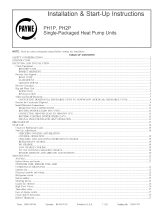
UNIT DAMAGE HAZARD
Failure to follow this caution may result in damage to unit
components.
When connecting ductwork to units, do not drill deeper
than 3/4 in. (19 mm) in shaded area shown in Fig. 2 or coil
may be damaged.
ELECTRICALSHOCK HAZARD
Failure to follow this warning could result in personal
iniury or death.
Before performing service or maintenance operations on the
system, turn off main power to unit and install lockout tag.
o
19.17 in. (487 mm) .----.4_ 13.92 in.I _--
(100 ram)
o
o
o o
o o o
A08003
Fig. 2 - Area Not to be Drilled More Than 3/4-in. (19 mm)
Deep
1. All units should have field-supplied filters or accessory
filter rack installed in the return-air side of the unit.
Recommended sizes for filters are shown in Table 1.
2. Avoid abrupt duct size increases and reductions. Abrupt
change in duct size adversely affects air performance.
IMPORTANT: Use flexible connectors between ductwork and
unit to prevent transmission of vibration. Use suitable gaskets to
ensure weather tight and airtight seal. When electric heat is
installed, use fireproof canvas (or similar heat resistant material)
connector between ductwork and unit discharge connection. If
flexible duct is used, insert a sheet metal sleeve inside duct. Heat
resistant duct connector (or sheet metal sleeve) must extend 24-in.
(610 mm) from electric heater element.
3. Size ductwork for cooling air quantity (cfm). The minimum
air quantity for proper electric heater operation is listed in
Table 2. Heater limit switches may trip at air quantities
below those recommended.
4. Seal, insulate, and weatherproof all external ductwork. Seal,
insulate and cover with a vapor barrier all ductwork passing
through conditioned spaces. Follow latest Sheet Metal and
Air Conditioning Contractors National Association
(SMACNA) and Air Conditioning Contractors Association
(ACCA) minimum installation standards for residential
heating and air conditioning systems.
5. Secure all ducts to building structure. Flash, weatherproof,
and vibration-isolate duct openings in wall or roof
according to good construction practices.
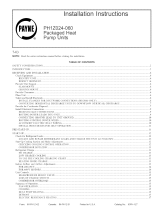
Fig. 6 shows a typical duct system with PH3Z unit installed.
Units are dedicated side supply products. They are not convertible
to vertical air supply. A field-supplied plenum must be used to
convert to vertical air discharge.
Step 6 -- Connect Condensate Drain
NOTE: When installing condensate drain connection be sure to
comply with local codes and restrictions.
Unit removes condensate through a 1-3/64 in. (27 mm) ID hole
(using 3/4-in. (19 mm) OD piping or tubing) which is located at
the end of the unit. See Fig. 5 for location of condensate
connection.
Condensate water can be drained directly onto the roof in rooftop
installations (where permitted) or onto a gravel apron in ground
level installations. Install a field-supplied condensate trap at end of
condensate connection to ensure proper drainage. Make sure that
the outlet of the trap is at least 1 in. (25 mm) lower than the drain
pan condensate connection to prevent the pan from overflowing
(See Fig. 3 and 4). When using a gravel apron, make sure it slopes
away from the unit.
If the installation requires draining the condensate water away from
the unit, install a 2-in. (51 mm) trap using a 3/4-in. (19 mm) OD
tubing or pipe. (See Fig. 3 and 4.) Make sure that the outlet of the
trap is at least 1 in. (25 mm) lower than the unit drain-pan
condensate connection to prevent the pan from overflowing. Prime
the trap with water. Connect a drain tube using a minimum of
3/4-in. (19 mm) PVC, 3/4-in. (19 mm) CPVC, or 3/4-in. copper
pipe (all field supplied). Do not undersize the tube. Pitch the drain
tube downward at a slope of at least 1 in. (25 mm) for every 10 ft
(3 m) of horizontal run. Be sure to check the drain tube for leaks.
Prime trap at the beginning of the cooling season start-up.
Allowable glues for condensate trap connection are: Standard
ABS, CPVC, or PVC cement..
1"(25 mm) MIN.
._ TRAP
2" (51 mm) MIN.
A08001
Fig. 3 - Condensate Trap
1" (25 mm) MIN.
TRAP
"(51 ram)MIN.
Fig. 4 - PVC Condensate Trap

I
_o
_o
m_
I
>
o
OQ
UNIT
_HBZ024
PH3Z03O
PHBZOBB
PHBZO42
PHBZO48
PHBZO60
!$r ....
i ,
@
"_ FULL LOUVER
i,
LEFT SIDE VIEW
ELECTRICAL
CHARACTERISTICS
208 230 1 60
208 230 1 60
208 230 1 60
208 230 1 60
208 230 1 60
208 230 1 60
UNIT WT UNIT HEIGHT
LBS KG A
293 133 3013 [765]
524 147 3413 [867]
371 I11 4218 [I070]
389 177 4213 [IOTO]
384 175 42 13 [I070]
433 197 4213 [I070]
CENTER OF GRAVITY MMIIN
X Y Z
140 [356] 19 0 [483] 15 O [381]
140 [356] 190 [483] 160 [aO6]
140 [356] 190 [483] 198 [503]
140 [356] 190 [483] 219 [556]
140 [356] 19 0 [483] 198 [503]
140 [356] 190 [483] 219 [556]
12950
[5098]
BOTTOM OF UNIT
t
RETURN SUPPLY
!
8125
BOTTOM OF UNIT
t
TOP VIEW
COMPRESSOR, CONTROL BOX ANB
INDOOR COIL ACCESS PANEL
\
\\ __
FULL LOUVER
,-- ,_ _n _ _:_ _
Z
0 ' 9
FRONT VIEW
9118
[35 90]
306
[120]
268 ID [I05]X 127 DPE50]--
CONDENSATE DRAIN
[2968]
7383
[2907]
DIA
EIIB]
POWER ENTRY
""_L-222 DIA
[088]
LOW VOLTAGE ENTRY
[1972]
RIGHTSIDE VIEW
REQUIRED CLEARANCES TO COMBUSTIBLE NATL.
MILLIMETERS [IN]
TOP OF UNIT .............................................. 0
BOTTOM OF UNIT .............................................. 0
SIDE OF UNIT WITH DUCT OPENINGS ............................. O
SIDE OF UNIT OPPOSITE DUCT OPENINGS ............... 0
NEC. REQUIRED CLEARANCES.
MILLIMETERS [IN]
BETWEEN UNITS, POWER ENTRY SIDE ..................... 10668 [4200]
UNIT AND UNGROUNDEDSURFACES, POWER ENTRY SIDE .......... 9140 [3600]
UNIT AND BLOCK OR CONCRETE WALLS AND OTHER
GROUNDED SURFACES, POWER ENTRY SIDE ............. I066 8 [4200]
REQUIRED CLEARANCE FOR SERVICII_
MILLIMETERS [IN]
TOP OF UNIT ........................... 9140 [3600]
SIDE OF UNIT OPPOSITE DUCT OPENINGS ..................... 7620 [3BOO]
SIDE OF UNIT WITH POWER ENTRY........................... 7620 [3000]
(EXCEPT FOR NEC REQUIREMENTS)
NOTE: CLEARANCES MUST BE MAINTAINED TO PREVENT RECIRCULATION OF AIR FROM
OUTDOOR FAN DISCHARGE A REMOVABLE FENCE OR BARRICADE REQUIRES NO
CLEARANCE
DIMENSIONS IN [] ARE IN INCHES
PANEL
5
[2 38]
ACCESS
_76
[975]
L_
_4767
[1877]
0
L¢356 O
[14 02]
DUCT OPENINGS
REAR VIEW
REV
50ZH500442 30

Power W_dng
-- ControlW_dng
_ Condenser A_rflow
_* Evaporat or Airflow
Fig. 6 - Typical Installation
A08207
Table 1 - Physical Data
UNIT SIZE 024 030 036 042 048 060
NOMINAL CAPACITY (ton) 2 2-1/2 3 3-1/2 4 5
OPERATING WEIGHT (Ib) 293 324 377 369 364 433
(kg) 133 147 171 176 174 196
COMPRESSOR Scroll Ultra Tech Scroll
REFRIGERANT (R-22)
Quantity (Ib) 7.5 10.3 10.3 11.9 11.4 13.3
(kg) 3.4 4.7 4.7 5.4 5.2 6.0
REFRIGERANT METERING DEVICE AccuRate( '_ TXV
0.067 0.067 0.082 0.086 - -
0.049 0.057 0.059 0.063 0.070 0.073
Copper Tubes, Aluminum Plate Fins
Orifice ID (in.)
Orifice OD (in.)
CONDENSER COIL
Rows... Fins/in.
Face Area (sq. ft.)
CONDENSER FAN
Nominal Cfm
Diameter (in.)
(mm)
Motor HP (RPM)
EVAPORATOR COIL
Rows... Fins/in.
Face Area (sq. ft.)
Evaporator blower
Nominal Airflow (Cfm)
Size (in.)
(mm)
Motor HP (RPM)
CONNECTING DUCT SIZES
Supply Air (in.)
(mm)
Return Air (in.)
(mm)
Return-Air Filters* Throwaway (in,)
(ram)
2...21 2...21 2...21 2...21 2...21
11.1 12.7 15.8 13.3 15.8
2600 2600 3200 3200 3300
20 20 20 20 20
508 508 508 508 508
1/8 (825) 1/8 (825) 1/4 (1100) 1/4 (1100) 1/2 (1100)
2...21
15.8
Propeller
3200
2O
508
1/4 (1100)
3...17 3...17 4...17 4...17
4.3 4.9 4.9 6.1
800 1000 1600 1875
10x8 11x10
254 x 203 279 x 254
1/2 (1050) 1/2 (1050) 1 (1050) 1 (1050)
Copper Tubes, Aluminum Plate Fins
4...17 4...17
4.9 6.1
Direct Drive
1200 1400
11x9
279 x 229
3/4 (1050) 3/4 (1050)
Round
14
356
14
356
24 x 24 24 x 30 30 x 30
610 x 610 610 x 762 762 x 762
*Requiredfiltersizesshown are based onthe ARI Airconditioning & Refrigerationlnstitute) rated airflow ata velocity of300ff/min(91 m) forthrowawaytype or
450 ft/min (137 m) for high capacity type. Recommended filters are 1-in. (25 mm) thick.

Table 2 - Minimum Airflow for Safe Electric Heater Operation
Minimum Airflow (CFM)
Unit Size
5kW 7.5kW 10kW 15kW 20kW
024 500 650 750 -
030 600 800 1050 -
036 600 800 1050 1150 1200
042 600 800 1050 1150 1200
048 600 800 1050 1150 1200
060 600 800 1050 1150 1200
Step 7 -- Install Electrical Connections
ELECTRICAL SHOCK HAZARD
Failure to follow this warning could result in personal
iniury or death.
The unit cabinet must have an uninterrupted, unbroken
electrical ground to nfininfize the possibility of personal
iniury if an electrical fault should occur. This ground may
consist of an electrical wire connected to the unit ground
screw in the control compartment, or conduit approved for
electrical ground when installed in accordance with NEC,
ANSI/NFPA 70 American National Standards Institute/
National Fire Protection Association (latest edition) (in
Canada, Canadian Electrical Code CSA C22.1) and local
electrical codes.
[]NIT COMPONENT DAMAGE HAZARD
Failure to follow this caution may result in damage to the
unit being installed.
1. Make all electrical connections in accordance with NEC
ANSI/NFPA 70 (latest edition) and local electrical codes
governing such wiring. In Canada, all electrical
connections must be in accordance with CSA standard
C22.1 Canadian Electrical Code Part 1 and applicable
local codes. Refer to unit wiring diagram.
2. Use only copper conductor for connections between
field-supplied electrical disconnect switch and unit. DO
NOT USE ALUMINUM WIRE.
3. Be sure that high-voltage power to unit is within
operating voltage range indicated on unit rating plate. On
3-phase units, ensure phases are balanced within 2
percent. Consult local power company for correction of
improper voltage and/or phase imbalance.
4. Do not damage internal components when drilling
through any panel to mount electrical hardware, conduit,
etc.
HIGH-VOLTAGE CONNECTIONS
The unit must have a separate electrical service with a
field-supplied, waterproof disconnect switch mounted at, or within
sight from the unit. Refer to the unit rating plate, NEC and local
codes for maximum fuse/circuit breaker size and minimum circuit
amps (ampacity) for wire sizing.
The field-supplied disconnect may be mounted on the unit over
the high-voltage inlet hole when the standard power and
low-voltage entry points are used. See Fig. 6 and 7 for acceptable
location.
Operation of unit on improper line voltage constitutes abuse and
may cause unit damage that could affect warranty.
ROUTING POWER LEADS INTO UNIT
Use only copper wire between disconnect and unit. The
high-voltage leads should be in a conduit until they enter the unit;
conduit ternfination at the unit must be watertight. Run the
high-voltage leads through the hole on the control box side of the
unit (See Fig. 7). When the leads are inside the unit, run leads to
the control box (See Fig. 8). For single-phase units, connect leads
to the black and yellow wires (See Fig. 9).
CONNECTING GROUND LEAD TO UNIT GROUND
Connect the ground lead to the chassis using the unit ground in the
control box (See Fig. 8 and 9).
ROUTING CONTROL POWER WIRES (24-V)
Form a drip-loop with the thermostat leads before routing them
into the unit. Route the thermostat leads through grommeted hole
provided in unit into unit control box (See Fig. 7). Connect
thermostat leads and unit power leads as shown in Fig. 9, 10 and
11.
Route thermostat wires through grommet providing a drip-loop at
the panel. Connect low-voltage leads to the thermostat as shown in
Fig. 10 & 11.
The unit transformer supplies 24-v power for complete system
including accessory electrical heater. Transformer is factory wired
for 230-v operation.
ACCESSORY ELECTRIC HEAT WIRING
Refer to accessory electric heat installation instructions for
information on installing accessory electric heat. Accessory electric
heat wiring is shown in Fig. 17 and 18.
HIGH-VOLTAGE POWER LOW-VOLTAGE WIRING
WIRING ENTRY HOLE ENTRY HOLE
(grommet hole)
oI
o /
/
©
Fig. 7 - []nit Electrical Connection
A08407

HEATER LOW
. VOLTAGE PLUG
Fig. 8 - Control Box Wiring
A05388
SINGLE-PHASE U
3-PHASE /CONNECTIONS _-
CONNECTIONS /TO DISCONNECTI .
TO DISCONNECT1PER NEO LL_ .....
PER NED / L.
L
UNIT GROUND
GROUND
LEAD
BLK- -/
- _- YEL- -/
_'-- BLU- -/
C00012
Fig. 9 - Line Power Connections
©
@-
@
@-
Thermostat
and subbase
IL--
_ RN
Z_ WHT
Unit Control
Power
Fig. 10 - Control Connections (Sizes 024-042)
A05207
0-
@-
Thermostat
and subbase
ql
11
RED
Unit Control
Power
Fig. 11 - Control Connections (Sizes 048-060)
PRE-START-UP
A05208
FIRE, EXPLOSION, ELECTRICAL SHOCK
HAZARD
Failure to follow this warning could result in personal
injury or death and/or property damage.
1. Follow recognized safety practices and wear protective
goggles when checking or servicing refrigerant system.
2. Relieve and recover all refrigerant from system before
touching or disturbing anything inside terminal box if
refrigerant leak is suspected around compressor
terminals.
3. Never attempt to repair soldered connection while
refrigerant system is under pressure.
4. Do not use torch to remove any component. System
contains oil and refrigerant under pressure.
5. To remove a component, wear protective goggles and
proceed as follows:
a. Shut off electrical power to unit and install
lockout tag.
b. Relieve and reclaim all refrigerant from system
using both high- and low-pressure ports.
c. Cut component connecting tubing with tubing
cutter and remove component from unit.
d. Carefully unsweat remaining tubing stubs when
necessary. Oil can ignite when exposed to flame.
Proceed as follows to inspect and prepare the unit for initial
start-up:
1. Remove all access panels.
2. Read and follow instructions on all DANGER, WARNING,
CAUTION, and INFORMATION labels attached to, or
shipped with unit.
3. Make the following inspections:
a. Inspect for shipping and handling damages, such as
broken lines, loose parts, disconnected wires, etc.
b. Inspect for oil at all refrigerant tubing connections and
on unit base. Detecting oil generally indicates a
refrigerant leak. Leak test all refrigerant tubing
connections using electronic leak detector, or
liquid-soap solution. If a refrigerant leak is detected, see
Check for Refrigerant Leaks section.

c.Inspectallfield- and factory-wiring connections. Be
sure that connections are completed and tight.
d. Ensure wires do not touch refrigerant tubing or sharp
sheet metal edges.
e. Inspect coil fins. If damaged during shipping and
handling, carefully straighten fins with a fin comb.
4. Verify the following conditions:
a. Make sure that outdoor-fan blade is correctly positioned
in fan orifice. Top edge of blade should be 3.125 in.(79
mm) down from outdoor coil outlet grille (size
024-048, See Fig. 19) or hub should be 0.708-in. (18
mm) away from motor end bell (size 060, See Fig. 19).
See Outdoor Fan Adjustment section.
b. Make sure that air filter is in place.
c. Make sure that condensate drain pan and trap are filled
with water to ensure proper drainage.
d. Make sure that all tools and miscellaneous loose parts
have been removed.
START-UP
Step 1 -- Check for Refrigerant Leaks
Proceed as follows to locate and repair a refrigerant leak and to
charge the unit:
1. Locate leak and make sure that refrigerant system pressure
has been relieved and reclaimed from both high- and
low-pressure ports.
2. Repair leak following accepted practices.
NOTE: Install a filter drier whenever the system has been opened
for repair.
Step 2 -- Start-Up Cooling and Make Adjust-
ments
Complete the required procedures given in the Pre-Start-Up
section before starting the unit. Do not jumper any safety devices
when operating the unit. Do not operate the unit in cooling mode
when the outdoor temperature is below 40°F (4.4°C) (unless
accessory low-ambient kit is installed). Do not rapid cycle the
compressor. Allow 5 min. between "on" cycles to prevent
compressor damage.
CHECKING COOLING AND HEATING CONTROL
OPERATION
Start and check the unit for proper cooling control operation as
follows:
1. Place room thermostat SYSTEM switch in OFF position.
Observe that blower motor starts when FAN switch is
placed in ON position and shuts down within 60 sec. (for
024-042) or 90 seconds (for 048 and 060) when FAN
switch is placed in AUTO position.
2. Place SYSTEM switch in COOL position and FAN switch
in AUTO position. Set control below room temperature.
Observe that compressor, outdoor fan, and indoor blower
motors start and that reversing valve shifts. Observe that
cooling cycle shuts down when control setting is satisfied.
Reversing valve (RV) remains energized.
3. Place system switch in HEAT position. Observe that
compressor, indoor fan and outdoor fan energize (Reversing
Valve is deenergized in heat pump heating mode). Set
control above room temperature. Observe that heating cycle
shuts down when control setting is satisfied.
4. When using an automatic changeover room thermostat,
place both SYSTEM and FAN switches in AUTO positions.
Observe that unit operates in Cooling mode when
temperature control is set to call for Cooling (below room
temperature), and unit operates in Heating mode when
temperature control is set to call for Heating (above room
temperature).
Step 3 -- Refrigerant Charge
Refrigerant Charge -- Amount of refrigerant charge is listed on
unit nameplate and in Table 1. Refer to Payne Refrigerant Service
Techniques Manual, Refrigerants section. Unit panels must be in
place when unit is operating during charging procedure. Unit must
operate a minimum of 15 minutes before checking charge.
NO CHARGE
Refer to Payne Refrigerant Service Techniques. Use standard
evacuating techniques. After evacuating system, weigh in the
specified amount of refrigerant (refer to Table 1).
LOW CHARGE COOLING
024-042 units:
1. Measure suction line pressure by attaching a gauge to the
service port.
2. Measure the suction line temperature by attaching a
temperature sensing device to it.
3. Insulate the temperature sensing device so that the outdoor
ambient doesn't affect the reading.
4. Locate the measured suction line pressure in the top row of
Table 5 and the measured outdoor ambient temperature in
the left column of the table. Based on the two values,
determine the required suction line temperature.
5. If the measured suction line temperature is greater than the
tabulated temperature, add charge in the system.
048 and 060 units:
1. Measure discharge line pressure by attaching a gauge to the
service port.
2. Measure the liquid line temperature by attaching a
temperature sensing device to it.
3. Insulate the temperature sensing device so that the outdoor
ambient doesn't affect the reading.
4. Refer to the required subcooling in Tables 3 to find the
required subcooling based on the model size and the
outdoor ambient temperature.
5. Interpolate if the outdoor temperature lies in between the
table values. Extrapolate if the temperature lies beyond the
table range.
6. Find the pressure value corresponding to the measured
pressure on the compressor discharge line.
7. Read across from the pressure reading to obtain the Liquid
line temperature for a required subcooling.
8. Add charge if the measured temperature is higher than the
liquid line temperature value in the table.
9. Add charge using the service connection on the suction line
of the compressor.
HEATING MODE CHARGE
Do not attempt to adjust charge by cooling methods while in heat
pump heating mode. Recover refrigerant and weigh in according to
unit data plate refrigerant data.

Model Size
048
049
060
Required Subcooling °F(°C)
Outdoor Ambient Temperature
75 (24) 82 (28) 85 (29) 95 (35) 105 (41)
18 (10) 17 (9 4) 17 (9 4} 16 (8 9) 14 (7 8)
2a (133) 23 (128) 22 (12 2} 22 (12 2) 20 (11 1/
21 (11 7) 21 111 7) 20 (11 1) 19 (10 6) 16 (8 9)
Charging Procedure (CHARGE SYSTEM IN HIGH CAPACITY)
- Measure Discharge line pressure by attaching a gauge to the
service port
2- Measure the Liquid line temperature by attaching a
temperature sensing device fo it
3- Insulate the temperature sensing device so that the Outdoor
Ambient doesn't affect the reading
4- Refer to the required Subcooling in the table to find the
required Subcooling based on the model size and the
Outdoor Ambient temperature
5- Interpolate if tile Outdoor temperature lies in between the
fable values
6- Find the Pressure Value corresponding to the measured
Pressure on the Compressor Discharge line
7- Read across from the Pressure reading to obtain the Liquid
line temperature for a required Subcooling
8- Add Charge if the measured temperature is higher than the
liquid line temperature value in the table
9- Add Charge using the service connection on the Suction line
of the Compressor
O-Remove charge it the measured temperature is lower than the
liquid line temperature in the table
Table 3 - Required Subcooling
Required Liquid Line Temperature for a Specific Subcooling (R-22)
Required Subcoolin9 (°F) Required Subcooling (°C)
Pressure Pressure
(psig) 5 10 15 20 (kPa) 3 6 8 11
134 71 66 61 56 924 24 22 19 16
141 74 69 64 59 972 26 23 21 18
156 80 75 70 65 1075 30 21 24 21
163 83 78 73 68 1124 31 28 26 23
170 86 81 76 71 1172 33 30 27 24
171 89 84 79 14 1220 34 31 29 26
184 91 86 81 76 1268 36 33 30 27
19! 94 89 84 79 1317 37 34 31 29
198 96 91 86 81 1365 38 36 33 30
205 98 93 88 83 1413 40 37 34 31
213 101 96 91 86 1468 4! 38 36 33
221 104 99 94 89 1524 43 40 37 34
229 106 101 96 91 1579 44 4! 38 36
237 108 103 98 93 1634 45 42 40 37
245 111 106 101 96 1689 47 44 41 38
253 113 108 103 98 1744 48 45 42 40
262 116 111 106 101 1806 49 46 44 41
271 118 113 108 103 1868 51 48 45 42
280 121 116 111 I06 1930 52 49 46 44
289 123 118 113 108 1992 53 51 48 45
298 125 120 115 110 2054 55 52 49 46
307 128 123 118 I13 2116 56 53 50 48
317 130 125 120 115 2185 57 54 52 49
327 132 127 122 117 2254 59 56 53 50
337 135 130 125 I20 2323 60 57 54 52
347 137 132 127 122 2392 6! 58 56 53
357 139 134 129 12A 2461 62 60 57 54
367 142 137 132 127 2530 64 61 58 55
Step 4 -- Indoor Airflow and Airflow Adjust-
ments
NOTE: For cooling operation, the recommended airflow is 350
to 450 cfm for each 12,000 Btuh of rated cooling c@acity.
Table 4 shows dry coil air delivery for horizontal discharge units.
Tables 6-8 show pressure drops.
NOTE: Be sure that all supply- and return-air grilles are open,
free from obstructions, and adjusted properly.
ELECTRICAL SHOCK HAZARD
Failure to follow this warning could result in personal
injury or death.
Disconnect electrical power to the unit and install lockout
tag before changing blower speed.
Airflow can be changed by changing the lead connections at the
blower motor. To change motor speeds, reposition wire at fan
motor speed terminals labeled 1-2-3-4 (refer to Fig. 12).
Remove the speed tap connector labeled 1 through 5 on the motor.
While looking at the connector end that is inserted into the motor,
gently pry the locking tab outward and remove the wire from the
connector. Insert the wire into the desired tap until it locks into
place. Be sure new airflow meets the range noted above and
minimum electric heat CFM, if equipped. Refer to Table 2 and 4.
All model sizes are factory wired or rated airflow operation.
DRAWING _UMBER REV !
50ZH500375 5.0
AO8406
1234
I
Fig. 12 - Motor Speed Selection
AO8412
FOR 208/230V BLOWER MOTORS
The motor lead speed connections are as follows:
SIZE RATED AIRFLOW HIGH AIRFLOW
024 Tap 1 Tap 3
030 Tap 2 Tap 4
036 Tap 1 Tap 3
042 Tap 2 Tap 4
RATED AIRFLOW HIGH AIRFLOW
SIZE Low High Low High
Stage Stage Stage Stage
048 Tap 1 Tap 3 Tap 2 Tap 4
060 Tap 1 Tap 3 Tap 2 Tap 4

Step 5 -- Unit Controls
All compressors have the following internal-protection controls.
HIGH-PRESSURE RELIEF VALVE
This valve opens when the pressure differential between the low
and high side becomes excessive.
LOSS OF CHARGE SWITCH
Located on the outdoor liquid line is a low-pressure switch which
functions as a loss-of-charge switch. This switch contains a
Schrader core depressor. This switch opens at 7 psig and closes at
22 psig. No adjustment is necessary.
COMPRESSOR OVERLOAD
This overload interrupts power to the compressor when either the
current or internal temperature become excessive, and
automatically resets when the internal temperature drops to a safe
level.
This overload may require up to 60 minutes (or longer) to reset;
therefore, if the internal overload is suspected of being open,
disconnect the electrical power to the unit and check the circuit
through the overload with an ohmmeter or continuity tester.
Step 6 -- Compressor Rotation
On 3-Phase units it is important to be certain compressor is
rotating in the proper direction. To determine whether or not
compressor is rotating in the proper direction:
1. Connect service gages to suction and discharge pressure
fittings.
2. Energize the compressor.
3. The suction pressure should drop and the discharge pressure
should rise, as is normal on any start-up.
If the suction pressure does not drop and the discharge pressure
does not rise to normal levels:
1. Turn off power to the unit and tag disconnect.
2. Reverse any two of the unit power leads.
3. Turn on power to the unit.
The suction and discharge pressure levels should now move to
their normal start-up levels.
NOTE: When the compressor is rotating in the wrong direction,
the unit makes an elevated level of noise and does not provide
cooling.
Step 7 -- Sequence of Operation
FAN OPERATION
The FAN switch on the thermostat controls indoor fan operation.
When the FAN switch is placed in the ON position, the IFR
(indoor-fan relay) is energized through the G terminal on the
thermostat. The normally-open contacts close, which then provide
power to the indoor (evaporator) fan motor (IFM). The IFM will
run continuously when the FAN switch is set to ON.
When the FAN switch is set to AUTO, the thermostat deenergizes
the IFR (provided there is not a call for cooling). The contacts open
and the IFM is deenergized. The IFM will be energized only when
there is a call for cooling, in heat pump heating mode or if the unit
is equipped with accessory electric heat, the indoor-fan motor will
also run while the accessory electric heat is energized.
NOTE: Some units are equipped with a time-delay relay. On
these units, the indoor fan remains on for 30 seconds after G or Y
is deenergized.
COOLING OPERATION (SIZES 024-042)
With a call for cooling (Y/Y2), the indoor fan energizes
immediately whereas the contactor energizes after a 5 minute time
delay (in case of initial start-up) starting the compressor and the
outdoor fan motor. When the cooling demand is met, Y/Y2
de-energizes, shutting the compressor, indoor fan and the outdoor
fan.
COOLING OPERATION (SIZES 048 AND 060)
These units utilize a 2 stage indoor thermostat. With a first stage
call for cooling (Y1), the indoor fan (low stage) energizes
immediately whereas the contactor energizes after a 5 minute time
delay (in case of an initial start-up) starting the compressor (low
stage) and the outdoor fan motor. If the low stage operation cannot
satisfy the cooling demand, the second stage cooling (Y2)
energizes switching the compressor into high stage cooling through
energizing an internal solenoid valve inside the scroll compressor
and switching the indoor fan into high stage. When second stage
cooling is satisfied, Y2 de-energizes switching the compressor and
the indoor fan into low stage cooling. When the low stage cooling
demand is met, Y1 de-energizes shutting the compressor, indoor
fan and the outdoor fan.
HEATING OPERATION (SIZES 024-042)
With a call for heating (Y1), the indoor fan (low stage) energizes
immediately whereas the contactor energizes after a 5 minute time
delay (in case of initial start-up) starting the compressor and the
outdoor fan motor. If Y/Y2 cannot satisfy the heating demand, the
auxiliary or backup heat (W2) energizes. In case of staged heating,
W3 is energized if the demand is not met. The highest airflow
selected is run while the electric heat is in operation. When heating
demand is met, W3, W2 and Y/Y2 sequentially de-energize
shutting the compressor, indoor fan and the outdoor fan.
HEATING OPERATION (SIZES 048 AND 060)
With a first stage call for heating (Y1), the indoor fan (low stage)
energizes immediately whereas the contactor energizes after a 5
minute time delay (in case of initial start-up) starting the
compressor (low stage) and the outdoor fan motor. If the low stage
oepration cannot satisfy the heating demand, the second stage
heating (Y2) energizes switching the compressor into high stage
heating through energizing an internal solenoid valve inside the
scroll compressor and switching the indoor fan into high stage. The
auxiliary or backup heat is controlled by a third stage (W2). If the
demand is not met, W3 is energized in case of staged heating.
When heating demand is satisfied, W3, W2 and Y2 sequentially
de-energize switching the compressor and the indoor fan into low
stage heating. When the low stage heating demand is met, Y1
de-energizes shutting the compressor, indoor fan and the outdoor
fan.
CONTINUOUS FAN
With the continuous Indoor fan option selected on the thermostat,
G is continuously energized. In case of 024-042 units, the selected
airflow setting is provided. In case of 048 and 060 units, the
system runs low stage (YI) airflow for continuous fan operation.
DEFROST
Defrost board (DB) is a time and temperature control, which
includes a field-selectable time period between checks for defrost
(30, 60, 90 and 120 minutes). The time period is factory-set at 60
minutes and should only be adjusted by a trained service person.
Electronic timer and defrost cycle start only when contactor is
energized and defrost thermostat (DFT) is closed.
Defrost mode is identical to Cooling mode. The outdoor fan motor
stops because of "OF1" and "OF2" contacts opening on the defrost
board, a bank of optional electric heat turns on to warm air
supplying the conditioned space.
ELECTRIC RESISTANCE HEATING
If accessory electric heaters are installed, on a call for second stage
or emergency heat, the thermostat energizes W which energizes the
heater relay and in turn energizes the electric heaters. The blower
motor is energized, unless already running in heat pump heating
mode. If the heaters are staged, W2 is energized when the second
stage of heating is required. When the need for heating is satisfied,
the heater and IFM are de-energized.
10

FIELD
SUPPLY
POWER_ BLI/
UNZT ONLY
MAXZMUM WIRE
SZZE 2 AWG IEL
EQUZP GNU
SCHEMATIC
FOR WIRING WITH r_=_ =" .... "3
ELECTRIC HEATERS I -i_ I
SEE SCHEMATIC i m II --
ON HEATER ACCESSORY. ''! I _ /
iC,, =,
I m
I m
L J
rrm- --_= -i
mli.7 -- I i
I LL _}P #
I i i
irrZZ_F< i
m ilOl
I I I
I I I
I I I
L .I I
G GRN
B RED
Y YEL
0 ORN
W2 WHT
W3 VIO
C BRN
OUTDOOR FAR
SECTION
UNZT COMPONENT ARRANGEMENT
CONTROLBOXAREA
R_NN
_ _ _7 BEFROS FAN
BOARD CONTROL
BOARD
ROMP
=
c
R .....
_-EQU]D
GRD
RED RED
FIELD SPLICE
O TERMINAL IMAR_ED) _
o TFR_INA_ (UNMARKED} P
o SPLICE CC_
O SPLICE {_ARKED) COMP
FACTORYW_R_NG CTD
FIELDCONTROLWIRING DB
FIELD POWERWIRING DFT
ACCESSORYOR OPTIONAL DR
WIRING FCB
_ND
TO ]ND1CATECO_ON _R
POTENTIALONLY: IFM
NOT TOREPRESENTW_R_NGLPN
HPS
OFM
RVN
TRAN
NOTES:
1 [F AN_OF THEORIGINALWIRESFU_HED ARE RE_LACEN,
[T MUSTBE REPLACED_[TH TYPE_0 NEGREEC WEREOR
IT'S EOUIVALE_T
Z SEE PRICE PAGESFORTHERMOSTATANNSUBNASES
3 USE75 DEGREECOPPERCONDUCTORSFOR FIELD INSTALLATION
4 FACTORYWIRINGFORSPEED SELECTORPLUG
024=I
OS6=_
04Z=N
N RELOCAT[O_OF SPEEDTAPS _AY BE REQUIRED
WHE_USINGFIELDI_STALLEOELECTRICHEATERS,
CONSULTINSTALLATIONI_STRUCTIO_STO
DETERMINECORRECTSPEEOTAPSETTING
_ "_0 NOTDISCONNECTPLNGUNDERLOAD"
ACCESSSORY ELECTRIC HEAT_
HRI,2,3 & 4 {20 KW_ _ERN BRN_
[ HR1,_N_B3RN(15 KWI .....
DIP SWl]CH SEll NGS
EAR SEQUENCE CTD (T1,TR) CONPRESSOR BELAY
& _ T;6O ....
O 5 SECT T*S MIN
G G C1 C1
ENERGIZED BE-ENERGIZED CLOSES OPENS
TSAT
Fig. 13 - Typical Single-Phase []nit Electrical Diagram (Sizes 024-042)
A08209
11

FIELD
SUPPLY
UNIT ONLY PO_
MAXIMUM WIRE
SIZE 2 AWG
EOUIP_GND
DR @ D_
SCHEMATIC
2081230-1-60
OUTDOORFAN
SECTION
r_
E5
r_
[_
I
I
L
COMP SOl ENO D
UNIT COMPONENT ARRANGEMENT
CONTROL BOX AREA
53_
_ DErRosr_R
HOARD CONTROL
HOARD
COMP
c
R 24V SPLICE
BOX
50ZH500374 10.(
A06405
Fig. 14 - Typical Single-Phase Unit Electrical Diagram (Sizes 048-060)
12

BLK
YEL
UNIT ONLY
MAXIMUM WIPE
SIZE z AWG
FIELD
SUPPLY
____
POWER
__ BLU
EOUIP_GND
SEESC_C ,am I I I
ON I-IEA"I'_ ACCESSORY. I _L'-- - -- -- k< I I
/"" '_ I I I
_Emil
mJ_r L........ I-- -- -- -I/l
I_,_ I-_ I I
iI _JIT=
I I
--GRN--
R--RED--
Y --YEL--
0 --ORN --
WR--W _T --
W3--VIO--
/
--BLK_
[RANI
I
DR @ DB
B_
YE_
SCHEMATIC
208/230-3-60
BLR_ OFM
CAP2 YEL
O_PRESSORPLUG
_EL
BLN ]G N
SEE NOTE #
C ---BRN
UNIT COMPONENT ARRANGEMENT
BRN
I
RED
DEFROST BOARD (DB)
PL I
ACCESSSORY ELECTRIC HEAT_
--I
DIP SWITCH SETTINGS
OUTDOOR FAN
SECTION
COI_TROLBOX AREA
_EQUIP
GRD
--Z4V POWER ENTRY
LEGEND
HRI (5 KW}_ "_ BRN
.WriT............._{_ BR_4
/
HRI,2 & 3 {15 IIW} --_
--BRN
_FIELD SPLICE
'_'TER_IRAL(NARKED) C CO_TACTOR
a TERN_NAL<URMARKED_ cCBAP CAPACITOR
0 SPLICE C_RCU_TBREAKER
_SPEICE (MARKED) CC_ CRANK CASEF_EA_ER
COMP COMPRESSORMOTOR
--PAC_ORY W_R_G CTO COmPReSSORrI_E DELAY
-- --FIELD CONTROLWIRING O_ DEFROSTBOARD
--- PILED POWER WIRIRG DF_ DEFROSTTHERMOSTAT
----ACC_SSOR_OR OPTiOnAL DR D_FROSTR_L_Y
WIRING _CD PAR CORTROLBOARD
GND GROUND
--TO _ND_CA]ECOMMON HR HEATER RE_AY
POtENTiALO_LY: IFM I_DOORFA_ NOTOR
NO_ TO REPRESEN__R_NG _PS _OW PRESSURESWl]C_
HPS HIGHPRESSURESWITCH
OFM OUTDOOR_A_ _OTOR
RVS REVERSINGVALVESOLEnOiD
TRAN TRANSFORMER
NOTES:
IIr ANY OF THEORIGINAL_IRESr_J_HEDARE REPLACED,
IT_UST BE REPLACEDWITHTYPE_0 _EGRE[C _IREOR
IT'SEQUIVALENT
_ SEE PRICEPAGESFOR THERMOSTATA_D SUB_ASES
USE 7SDEGREECOPPERCONDUCTORSfOR rIELD INST_LLATION
4 FACTORYWIRINGFOR SPEE_SELECTORPLUG
02_=I
O_O=_
03_=I
04Z=_
5 RELOCATIONor SPEEDTAPS_AY BE REQUIRED
WHEN_S[_GFIELD I_STALLEDELECTRICHEATERS
CONSULTINSTALLATIONI_STRUCTIO_STO
DETERMINECORRECTSPEEDTAP SETTING
_ %O _OT D_SCO_NECTPLUGU_DERLOAD'
DEFROST _IL_ I_R_INAT_ ]N 30 SIC IF _F_ OPeN
D{FROST_ILLT{R_NAT{_ORMALLYIF_FI _sCLOSED
FA_ SEQUENCE CTD (TI,TE} COMPRESSOR DELAY
ENERGIZED DEENERGIZED CLOSES OPENS
TSAT
Sizes 030-042)
I 50ZN500453 Iso
A06325
Fig. 15 - Typical Three-Phase Unit Electrical Diagram
13

FIELD
SUPPLY
UNIT ONLY BL_
MAXIMUM WIRE
SIZE 2 AWG 1-1 YEL
POWER
__ 5LU
EOIP_GND
0 --ORN --
W2IWHT --
Y2 --PNK--
ws--VlO--
OUTBOOR FAN
SECTION
rssq
F_Sq
C --BRN
UNIT COMPONENT ARRANGEMENT
CONTROLBOXAREA
BEPROSE PAN
BOARD CONTROL
BOARD
PL I
J
c
[
R E_V SPLICE
BOX
-- RED RED --
DEFROST BOARD(DB)
I
I
I
_EOUIP
B_B
IE4V POWER E_TBY
EGEND
_;]EL8 SPLICE
_TERMINAL (_A_KED} C CBNTACTOR
o _ER_INA__ARKED) CAP CAPACITOR
o SPLICE CB CIRC_ITBREAKER
_SPLICE (_AR_ED_ CC_ CRA_KCASE NEATER
EO_P COMPRESSOR_O_OR
I FACtORYWIRING ETB COMPRESSORII_EDEIAY
- --FIELDCONTROLW_RINB D_ DEFROST_O_RD
I- F_ELB POWER_IR[_G DFI¸ DEPROST_H_R_OSIA_
----ACCESSORYOR OP_;O_AL DR DE_ROSTRELAY
WIRING rCB rA_ CONTROLBOARD
GRD DROURD
I_O INDICATECOMMO_ HR HEA_ERRELA_
POTENTIALO_LT: IF_ INDOORPAR _OTOR
NBT _0 REPRESERTW_RIND EPS EOW PRESSUH_SWITCH
HPS HIGHPRESSURESWITCH
OF_ OUTDOORrA_ _OTOR
RVS REVERSinGVALVE SqE_OID
TRA_ TRAnSFORmER
BLU _PS BEU
F
BLK
I
@E_ROST_LL TER.[_A?{I_30SEE Ir D;To_
_EFROS$_]L£$Eff_I_A_ENOR_AL£YIFOFT ISCLOSE_
NOTES
I IF A_Y or THE ORIGINAL WIRES F_RNISBED ARE REPLACED, IAN SEQUENCE CTB (PI,T2) COMPRESSOR DELAY
IT _UST BE REPLACED _ITB TYPE 90 DEGREE C _IRE OR
IT'S EQUIVALENT
SEE PRICE PAGES FOR TBER.OSTAT AND SUBBASES ; _ T;9O ; ; SEE i T_ _IN
_SE 75 DEGREE COPPER CONDUCTORS FOR FIELD INSTALLATION B G C1 C1
4 RELOCATION OF SPEED TAPS _AY 8E REQUIRED ENERGIZED DE-ENERGIZED CLOSES OPENS
WHEN gSlNG FIELD INSTALLED ELECTRIC HEATERS, TSAT
CONSULT E_STALLATIO_ I_STRUCTIONS TO
DETERminE CORRECT SPEED TAP SETTING
S 'DO NOT DISCONNECT PLUG UNDER LOAD"
50ZH500454 3 0
A06826
Fig. 16 - Typical Three-Phase []nit Electrical Diagram (Sizes 048-060)
14

0..,A. _[,_
CONTROL P L UG
BOARD B RN
] WHT
STEP VlO
S,EP_--[_P_GRY
TO
0..T_w,O,_--_£t_--_
,- .................1 __t_ I
_,_ _iI__ _
SINGLE POINT I<IT l
I
:" J
I I RELAY 1
i_ I I L_ _--B_--BRN--¢I EL1 AUTO LIMIT
I BLK YEL
I
I I I
]! I RELAY 2 I
i I I
I "_-- -- --_--BRN-- _ EL2 AUTO LIMIT
I _BL_' _ _ YEL
I I RELAY_ , I
_-I---_-_RN-+ EL_ AUTOLIMIT
___L_,-- YEL--I
I I
I RELAY 4 I l
!---_-ORN-= EL,AUTOLIMITI
_BLK -- YEL -_1
Fig. 17 - Single-Phase Accessory Electric Heater Wiring
A05209
IO UNIT POWER
WIRING
2 W3 VIOLET
S,EP ................[::Z,3 __ _ = g
,,
WIRING 24VAC [ [ NR3 _1 "
EL_ AUTO-LIMIT BLUE •
Q$
EL3 AUTO=L _N_T
• _ . BLACK J
Fig. 18 - Three-Phase Accessory Electric Heater Wiring
L1
L2
L3
A06327
15

Table 4 - Dry Coil Air Delivery* Horizontal Discharge
(Deduct 10 percent for 208 Volt Operation)
230 VOLT HORIZONTAL DISCHARGE
UNIT SPEED AIR EXTERNAL STATIC PRESSURE (IN. WC)
SIZE TAP DELIVERY 0.1 0.2 0.3 0.4 0.5 0.6 0.7 0.8 0.9 1.0
Watts -- 99 100 118 130 142 ....
1
CFM -- 848 793 757 698 632 ....
024
Watts ..... 222 233 244 257 260
2
CFM ..... 970 918 861 795 729
Watts -- 155 146 157 170 .....
2
CFM -- 1108 995 951 884 .....
030
Watts ..... 261 275 286 291 315
3
CFM ..... 1117 1053 1014 980 877
Watts 180 166 179 191 204 216 ....
1
CFM 1344 1215 1172 1136 1095 1051 ....
036
Watts -- -- -- 261 276 290 301 316 329 342
2
CFM -- -- -- 1343 1304 1272 1234 1190 1148 1100
Watts 269 283 305 321 336 349 360 -- -- --
3
CFM 1440 1404 1369 1333 1301 1273 1239 -- -- --
042
Watts -- -- 418 432 450 465 480 490 503 518
4
CFM -- -- 1572 1543 1504 1475 1441 1418 1380 1332
Watts -- 204 209 216 229 236 249 -- -- --
1
CFM -- 1129 1087 1027 994 932 881 -- -- --
Watts -- -- 233 245 254 266 276 289 -- --
2
CFM -- -- 1164 1122 1066 1025 954 906 -- --
048
Watts 386 398 409 418 425 435 438 441 451 --
3
CFM 1680 1652 1625 1583 1555 1515 1477 1444 1403 --
Watts -- 440 448 457 462 469 477 480 485 486
4
CFM -- 1745 1717 1684 1651 1612 1573 1537 1508 1470
Watts 224 235 251 266 277 291 298 -- -- --
1
CFM 1334 1288 1259 1224 1181 1157 1117 -- -- --
Watts -- -- 286 301 311 325 333 344 370 --
2
CFM -- -- 1333 1296 1261 1232 1199 1170 1062 --
060
Watts 608 626 643 660 668 685 697 -- -- --
3
CFM 1931 1900 1878 1844 1817 1789 1755 -- -- --
Watts 737 755 770 787 799 817 826 812 782 --
4
CFM 2093 2061 2028 2001 1971 1934 1899 1850 1757 --
*Air delivery values are based on operating voltage of 230v, wet coil, without filter or electric heater. Deduct filter and electric heater pressure drops to obtain
static pressure available for ducting.
NOTES:
1. Do not operate the unit at a cooling airflow that is less than 350 cfm for each 12,000 Btuh of rated cooling capacity. Evaporator coil frosting may occur at air-
flows below this point.
2. Dashes indicate portions of table that are beyond the blower motor capacity or are not recommended.
16

Table 5 - Cooling Charging Chart
SUCTION LINETEMPERATURE(°F)
Suction Line Pressure(PSIG)
ODTemp. 52 54 56 59 61 64 67 70 73 76 79 82 85 89 92
(°F)
45 51 55 60 64 69 ..........
55 -- -- 53 57 62 66 70 ........
65 .... 53 57 62 66 71 75 .....
75 ....... 56 61 66 71 76 -- -- --
85 ........ 53 58 63 67 72 -- --
95 ......... 50 54 58 62 66 --
105 .......... 50 53 57 60 64
115 .......... 49 52 55 58 61
125 ........... 50 53 56 59
SUCTION LINE TEMPERATURE(°C)
Suction Line Pressure(kPa)
ODTemp. 361 370 387 405 423 442 462 482 502 523 544 566 589 612 636
(oc)
7 11 13 15 18 21 ..........
13 -- -- 12 14 16 19 21 ........
18 .... 12 14 17 19 21 24 .....
24 ....... 13 16 19 22 24 -- -- --
29 ........ 12 14 17 20 22 -- --
35 ......... 10 12 14 17 19 --
41 .......... 10 12 14 16 18
46 .......... 9 11 13 14 16
52 ........... 10 11 13 15
MAINTENANCE
To ensure continuing high performance, and to minimize the
possibility of premature equipment failure, periodic maintenance
must be performed on this equipment. This unit should be
inspected at least once each year by a qualified service person. To
troubleshoot unit, refer to Troubleshooting Chart in back of book.
NOTE TO EQUIPMENT OWNER: Consult your local dealer
about the availability of a maintenance contract.
PERSONAL INJURY AND UNIT DAMAGE
HAZARD
Failure to follow this warning could result in personal
iniury or death and possible unit component damage.
The ability to properly perform maintenance on this
equipment requires certain expertise, mechanical skills,
tools and equipment. If you do not possess these, do not
attempt to perform any maintenance on this equipment,
other than those procedures recommended in the Owner's
Manual.
The minimum maintenance requirements for this equipment are as
follows:
1. Inspect air filter(s) each month. Clean or replace when
necessary.
2. Inspect indoor coil, drain pan, and condensate drain each
cooling season for cleanliness. Clean when necessary.
3. Inspect blower motor and wheel for cleanliness each
cooling season. Clean when necessary.
4. Check electrical connections for tightness and controls for
proper operation each cooling season. Service when
necessary.
5. Ensure electric wires are not in contact with refrigerant
tubing or sharp metal edges.
ELECTRICAL SHOCK HAZARD
Failure to follow these warnings could result in personal
iniury or death:
1, Turn off electrical power to the unit before performing
any maintenance or service on this unit.
2. Use extreme caution when removing panels and parts.
3, Never place anything combustible either on or in contact
with the unit.
Step 1 -- Air Filter
IMPORTANT: Never operate the unit without a suitable airfilter
in the return-air duct system. Always replace the filter with the
same dimensional size and type as originally installed. See Table 1
for recommended filter sizes.
Inspect air filter(s) at least once each month and replace
(throwaway-type) or clean (cleanable-type) at least twice during
each cooling season and twice during the heating season, or
whenever the filter becomes clogged with dust and lint.
Step 2 -- Unit Top Removal
NOTE: When performing maintenance or service procedures that
require removal of the unit top, be sure to perform all of the routine
maintenance procedures that require top removal, including coil
inspection and cleaning, and condensate drain pan inspection and
cleaning.
ELECTRICAL SHOCK HAZARD
Failure to follow this warning could result in personal
iniury or death.
Disconnect and tag electrical power to the unit before
removing top.
17

Onlyqualifiedservicepersonnelshouldperformmaintenanceand
serviceproceduresthatrequireunittopremoval.
Refertothefollowingtopremovalprocedures:
1.Removescrewsonunittopcoversurface.(Saveallscrews.)
2.Removescrewsonunittopcoverflange.(Saveallscrews.)
3.Lifttopfromunitcarefully.Settoponedgeandmakesure
thattopissupportedbyunitsidethatisoppositeduct(or
plenum)side.
4.Carefullyreplaceandsecureunittoptounit,usingscrews
removedinSteps1and2,whenmaintenanceand/orservice
proceduresarecompleted.
Step 3 -- Indoor Blower and Motor
For longer life, operating economy, and continuing efficiency,
clean accumulated dirt and grease from the blower wheel and
motor annually.
I
ELECTRICALSHOCK HAZARD
Failure to follow this warning could result in personal
injury or death.
Disconnect and tag electrical power to the unit before
cleaning and lubricating the blower motor and wheel.
To clean the blower wheel:
1. Remove the blower housing:
a. Remove the screws on the external side of the duct
panel that fasten the housing to the duct panel assembly.
b. Remove the side access panel and unscrew the
mounting bracket that fastens the blower housing to the
internal partition panel fo the control box assembly.
c. Make sure that the blower housing is supported by hand
before completely removing the mounting bracket.
d. Slide the blower housing from the rails of the duct panel
and place it outside the unit.
2. Remove the blower wheel from the housing:
a. Loosen the set screw which secures the wheel to the
motor shaft.
b. Loosen the three mounting legs of the motor by
removing the bolts that fasten themounting legs to the
housing.
c. Slide out the motor assembly (motor, belly band and the
3 mounting legs) from the hub of the wheel.
d. Remove the filler panel at the discharge end of the
blower housing by removing the two screws that fasten
it to the housing.
e. Remove the wheel form the housing.
3. Remove the caked on dirt from the wheel and the motor
using a brush.
4. Remove lint and dirt accumulations from the wheel and
housing with a vacuum cleaner, using a soft brush
attachment.
5. Remove grease and oil with a mild solvent.
6. Reassemble
a. Slip the wheel back in the housing with the hub set
screw parented in the correct direction.
b. Install the filler panel.
c. Reinsert the motor assembly in the wheel hub and align
the mounting legs with the housing mounting hold
locations.
d. Tighten the mounting bolts to fasten the motor assembly
with the housing.
e. Center the wheel in the housing by sliding it, align the
flat end of the shaft with the set screw and tighten the
set screw.
f. Slide back the blower housing into the mounting rails in
the duct panel and install the mounting bracket back in
its position.
g. Install the screws on the external side of the duct panel
to fasten duct panel with the housing.
h. Replace the side access panel.
Table 6 -Wet Coil Pressure Drop
UNIT STANDARD CFM (S.C.EM.)
SIZE 600 700 800 900 1000 1100 1200 1300 1400 1500 1600 1700 1800 1900 2000
024 .027 .034 040 .047 .053 - - -
030 .036 .042 .050 .055 .063 .072 .081 - -
036 - - .050 .055 .063 .072 .081 .090 .097 - -
042 - - .042 .049 .052 .059 .065 .071 .078 .085 .091
048 .... .072 .081 .090 .097 .108 .120 .129 .139
060 .... .071 .078 .085 .091 .098 .114
UNIT SIZE
024-036
042-060
FILTER
SiZE in.
(mm)
24 x 24
610 x 610
30 x 30
762 x 762
500 600
0.06 0.07
Table 7 - Filter Pressure Drop (in. wc)
CFM
700 800 900 1000 1100 1200 1300 1400 1500 1600 1700 1800 1900 2000 2100 2200 2300
0.08 0.08 0.09 0.09 0.09 0.10 0.11 0.12 0.14 0.15
0.08 0.09 0.10 0.11 0.12 0.13 0.14 0.15 0.16 0.17 0.18
Table 8 - Accessory Electric Heat Pressure Drop (in. wc)
HEATER CFM
kW 600 800 1000 1200 1400 1600 1800 2000 2200
5-20 0.06 0.08 0.10 0.13 0.15 0.18 0.20 0.23 0.25
18

Step 4 -- Outdoor Coil, Indoor Coil, and
Condensate Drain Pan
Inspect the condenser coil, evaporator coil, and condensate drain
pan at least once each year.
The coils are easily cleaned when dry; therefore, inspect and clean
the coils either before or after each cooling season. Remove all
obstructions, including weeds and shrubs, that interfere with the
airflow through the condenser coil.
Straighten bent fins with a fin comb. If coated with dirt or lint,
clean the coils with a vacuum cleaner, using the soft brush
attachment. Be careful not to bend the fins. If coated with oil or
grease, clean the coils with a mild detergent and water solution.
Rinse coils with clear water, using a garden hose. Be careful not to
splash water on motors, insulation, wiring, or air filter(s). For best
results, spray condenser coil fins from inside to outside the unit. On
units with an outer and inner condenser coil, be sure to clean
between the coils. Be sure to flush all dirt and debris from the unit
base.
Inspect the drain pan and condensate drain line when inspecting
the coils. Clean the drain pan and condensate drain by removing all
foreign matter from the pan. Flush the pan and drain trough with
clear water. Do not splash water on the insulation, motor, wiring, or
air filter(s). If the drain trough is restricted, clear it with a
"plumbers snake" or similar probe device.
Step 5 -- Outdoor Fan
UNIT OPERATION HAZARD
Failure to follow this caution may result in damage to unit
components.
Keep the condenser fan free from all obstructions to ensure
proper cooling operation. Never place articles on top of
unit.
1. Shut off unit power supply and install lockout tag.
2. Remove outdoor-fan assembly (grille, motor, motor cover,
and fan) by removing screws and flipping assembly onto
unit top cover.
3. Loosen fan hub setscrews.
4. Adjust fan height as shown in Fig. 19.
5. Tighten setscrews.
6. Replace outdoor-fan assembly.
15/32-in. (42 mm)
A08004
Fig. 19 - Outdoor Fan Adjustment
Step 6 -- Electrical Controls and Wiring
Inspect and check the electrical controls and wiring annually. Be
sure to turn off the electrical power to the unit.
Remove access panel to locate all the electrical controls and wiring.
Check all electrical connections for tightness. Tighten all screw
connections. If any smoky or burned connections are noticed,
disassemble the connection, clean all the parts, re-strip the wire
end and reassemble the connection properly and securely.
Check to ensure no wires are touching refrigerant tubing or sharp
sheet metal edges. Move and secure wires to isolate from tubing
and sheet metal edges.
After inspecting the electrical controls and wiring, replace all the
panels. Start the unit, and observe at least one complete cooling
cycle to ensure proper operation. If discrepancies are observed in
operating cycle, or if a suspected malfunction has occurred, check
each electrical component with the proper electrical
instrumentation. Refer to the unit wiring label when making these
checks.
Step 7 -- Refrigerant Circuit
Inspect all refrigerant tubing connections and the unit base for oil
accunmlation annually. Detecting oil generally indicates a
refrigerant leak.
If oil is detected or if low performance is suspected, leak test all
refrigerant tubing using an electronic leak detector, or liquid-soap
solution. If a refrigerant leak is detected, refer to Check for
Refrigerant Leaks section.
If no refrigerant leaks are found and low performance is suspected,
refer to Checking and Adjusting Refrigerant Charge section.
Step 8 -- Indoor Airflow
The heating and/or cooling airflow does not require checking
unless improper performance is suspected. If a problem exists, be
sure that all supply- and return-air grilles are open and free from
obstructions, and that the air filter is clean.
Step 9 -- Metering Devices
Refrigerant cooling metering device is an AccuRater (024-042) or
TXV (048 and 060) located upstream of the indoor coil distributor
assembly. Refrigerant heating mode metering device is an
AccuRater located upstrem of the outdoor coil distributor
assembly.
Step 10 -- Liquid Line Strainers
The liquid line strainers (to protect metering devices) are made of
wire mesh and are located in the liquid lines on the inlet side of the
metering devices.
Step 11 -- High Flow Valves
High flow valves are located on the compressor hot gas and suction
tubes. Large black plastic caps distinguish these valves with
O-rings located inside the caps. These valves can not be accessed
for service in the field. Ensure the plastic caps are in place and tight
or the possibility of refrigerant leakage could occur.
TROUBLESHOOTING
Refer to the Troubleshooting Chart (Table 9) for troubleshooting
information.
START-UP CHECKLIST
Use the Start-Up Checklist at the back of this manual.
19

Check Valves
A Open
B Closed
OUTDOOR COIL
L
f
LCS
C Open
D Closed
LEGEND
LCS Loss of Charge Switch
D Acutrol Metering Device
] Check Valve indicates direction of
(Arrow flow)
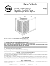
HEATING CYCLE
1. Hot gas from compressor flows through the 4-way valve and is
directed to the cooling liquid line check valve, tt is then condensed
and directed through subcooling circuits and out to the strainer
and the check valve in the heating liquid line,
2. The refrigerant then feeds the outdoor coi! through the Acutrol
metering device on each circuit.
3. Each circuit evaporates the refrigerant and the circuits are com-
bined in the outdoor header with some of the circuits flowing through
the check valve,
4. The refrigerant then flows through the 4-way valve, accumulator,
and back to the compressor.
Fig. 20 - Typical Heat Pump Operation, Heating Mode
C95045
Check Valves
A Closed
B Open
OUTDOOR COIL
INDOOR COIL
LOS
C Closed
D Open
LEGEND
LCS Loss of Charge Switch
] Acutrol Metering Device
] Check Valve (Arrow indicates direction of flow)
COOLING CYCLE
1. Hot gas from compressor flows through the 4-way valve and is
directed to the heating liquid line check valve, tt is then con-
densed and subcooted through converging circuits. Refrigerant leaves
the outdoor coil by way of the strainer and the check valve in the
cooling liquid line,
2. The refrigerant then feeds the indoor coi! through the Acutrol
metering device on each circuit.
3. Each circuit evaporates the refrigerant and the circuits are com-
bined in the indoor coil header with some of the circuits flowing
through the check valve,
4. The refrigerant then flows through the 4-way valve, accumulator,
and back to the compressor.
Fig. 21 - Typical Heat Pump Operation, Cooling Mode
20
C95044
/