Page is loading ...

& Start-Up Instructions
PHI P, PH2P
Single-Packaged Heat Pump Units
NOTE: Read the entire instl_action manual before starting the installation
TABLE OF CONTENTS
SAFETY ( ONSIDERATIONS 2
INTRODUCTION .......................................................................................................................................................................................................... 2
RECEIVrNG AND INSTALLATION .......................................................................................................................................................................... 2
Check Equipment ..................................................................................................................................................................................................... 2
IDENTIFY UNIT ................................................................................................ 2
INSPECT SHIPMENT ............................................................................................ 3
Provide Lnit Support ................................................................................................. 3
ROOF CURB ...................................................................................................................................................................................................... 3
SLAB MOUNT ................................................................................................................................................................................................... 4
GROUND MOUNT ............................................................................................... 4
Provide Clearances ................................................................................................. 5
Rig and Place Unit ................................................................................................................................................................................................... 5
INSPE( TION ...................................................................................................................................................................................................... 5
INSTALLATION ................................................................................................................................................................................................ 5
Select and Install Ductwork ................................................................................................ 7
CONVERTING HORIZONTAL DIS(HARGE UNITS TO DOVv_FLOW (VERTICAL) DIS(HARGE UNITS .................... 8
Provide fbr (ondensate Disposal ................................................................................... 9
Install Electrical Connections ....................................................................................... 11
HIGH-VOLTAGE ( ONNECTIONS ....................................................................................
ROUTING POWER LEADS INTO UNIT .............................................................................. 11
CONNE(TING GROUND LEAD TO GROUND LUG ............................................................ 11
ROUTING (ONTR()L POWER WIRES (24-V) ......................................................................... 11
SPE(IAL PRO(EDURES FOR 208-V OPERATION .................................................................. 13
PRE-START-L P ...................................................................................................... 17
START-UP ............................................................................................................... 18
(beck for Refi'igerant Leaks ........................................................................................ 18
Start-Up Adjustments .............................................................................................. 19
CHECKING (00LING AND HEATING
CONTROL OPERATION ........................................................................................... I9
CHE(KING AND ADJUSTING REFRIGERANT (HARGE ........................................................ 19
REFRIGERANT CHARGE ........................................................................................... I9
NO CHARGE 19
LOW CHARGE COOLING 19
TO USE COOLING CHARGING (HARTS 19
INDOOR AIRFLOW AND AIRFLOW ADJUSTMENTS 20
MAINTENANCE 21
Air Filter 22
Indoor blower and motor 22
OUTDOOR COIL, INDOOR (OIL, AND
CONDENSATE DRAIN PAN 22
Outdoor fhn 23
Electrical controls and wiring 24
Refrigerant circuit 25
Indoor airflow ......................................................................................................................................................................................................... 25
Metering device ...................................................................................................................................................................................................... 25
Liquid line strainers ................................................................................................................................................................................................ 26
High Flow Valves .................................................................................................................................................................................................. 26
Time-delay relay 27
Loss of"charge switch 27
Check defiost them_ostat 27
Defi'ost Thermostat 27
Form: IM-PH1P-04 Cancels: tM-PHIP-03 Printed in U.S.A. 11-02 Catalog No. 53PH-1P7

TROUBLESHOOTING 27
START-UP ( HECKLIST 27
NOTE TO INSTALLER READ THESE INSTRU(TIONS (AREFULLY AND COMPLETELY befbre installing this unit. Also, make sure
the Owner's Manual and Service Instl_/ctions are left with the unit after installation.
C99001
Fig. l--ModeJ PHIP/PH2P
SAFETY CONSIDERATIONS
Installation and servicing of air=conditioning equipment can be hazardous due to system pressure and electrical components Only trained and
qualified personnel should install, repair, or service air-conditioning equipment.
Untrained personnel can perform basic maintenance fkmctions of cleaning coils and filters. All other operations should be performed by tlained
service personnel. When working on air-conditioning equipment, observe precautions in the literature, tags, and labels attached to the unit, and
other safety precautions that may apply.
Follow all safety codes. Wear safety glasses and work gloves. Use quenching cloth for unbrazing operations. Have fire extinguisher available for
all brazing operations.
Z_ WARNING: Improper installation, adjustment, aReration, service, maintenance, or use can cause explosion, fire,
electric shock, or other occurrences, which could cause serious injury or death or damage your property. ConsuR a qualified
installer or service agency for information or assistance. The qualified installer or agency must use only factory-authorized
kits or accessories when modifying this product.
Recognize safety information. This is the safBty=alert symbolz_ x . When you see this symbol on the product or in instructions or manuals, be alert
to the potential for personal iajury.
Understand the signal words DANGER, WARNING, CAUTION, and NOTE. Danger identifies the most serious hazards, which will result in
severe personal injury or death. Warning indicates a condition that could cause serious personal injury or death. Caution is used to identif)- unsafe
practices, which would result in minor personal injury or product and property damage. NOTE is used to highlight suggestions which will result
in enhanced installation, reliability, or operation.
1. The power supply (volts, phase, and hertz) must cot_'espond to that specified on unit rating plate.
2. The electrical supply provided by the utility must be sufEcient to handle toad imposed by this unit.
3. This installation must cont'orm with local building codes and with NEC (National Electrical Code). Refer to provincial and local plurnbing
or waste water codes and other applicable local codes.
Z_ WARNmNG: Before performing service or maintenance operations on system, turn off main power to unit. Turn off
accessory heater power switch if applicable. Electrical shock could cause severe injury or death.
INTRODUCTmON
The PH1P and PH2P heat pumps are fully self-contained and designed for outdoor installation (See Fig. 1). Standard units are shipped in a
horizontal=discharge configuration _br installation on a ground=level slab. Units can be converted to downflow (vertical) discharge configurations
fbr rooftop applications.
RECEBMmNG AND INSTALLATION
PROCEDURE I--CHECK EQUBPMENT
A. BDENTIFY UNIT
The unit model number and serial number are stamped on the unit identification plate Check this inJ:bm_ation against shipping papers
2

• EVAPORA/OR CO_L
CORNER4 L_
TOP VIEW
l .............
4020
_15831
117¸7
[463]
IlJllJllJitllllI]lllt
i tlJtIIIIJltlIItlIIIItL
_UCT
.... OPEN NG
J i
-5505 .................
!983) [21 6T} [9 83]
883 _ _ ......
_s4B_ REAR VIEW
REQUIRED CLEARANCES TO COMBUS_BLE MATL.
MULIMETERS /IN]
10P O_ UNII .......................... 3556 [14 OOJ
DUCT SIDE OF UNiT ......................................... 508 1200]
SIDE OPPOSITE DUCTS ........................ 3556 [140O]
BOTTOM OF UNIT ..................................... IRT [050]
EIECTRIC HEAT PANEl...................................... 9144 [3NDD]
NEC. REQUIRE) CLEARANCES.
MIILIMETERS IIN]
BETWEEN UNITS, POWER [NTRT SIDE ............... lORD8 [4200]
UNIT AND UNGROUNDED SURFACES. POWER ENTRY SIDE .......... 9140 [3600]
UNIT AND DLOC_ OR CONCREIE WALLS AND OTIER
GROUNDED SURFACES, POWER ENTRY S!DE .................... _ODD8 [4200]
I_QUIP_) CLEARANCE FOR OP_A_ON AND SERV_INC
MILLIMETERS EJN1
EVAP COIL ACCESS S_DE .................. 9F4 O [3600]
POWER ENTRY SiDE ........................................ 9[40 [360D]
(EXCEPT FOR NEC REQUIREMENTS)
UNIT TOP ......................................... 9F4 O [3600]
SIDE OPPOSITE DUCTS ..................................... 9140 [BROO]
DUCI PANEL .................... 304 B IIROOD
,MINIMUM DISTANCES:IF UNIT IS PIACED LESS THAN 3048 !I?DO] FROM WAIL
SYSTEM,THEN SYSTEM PERFORMANCE MAYBE COMPROMISED
DIMENSIONS IN [] ARE }N }NCHES
91!
Z
[3272] _DRAIN 0UT[E]
LEFT SIDE VIEW _90 [0 ?S] N PT
220 [087] DP
[47 00]
t
i]4j iJJ-JJiiiJ IIJlJii
IIIII IIIIIIIIIH
\.
_2;6 3
{48 281
FRONT VIEW
{1087]
BT_
[3¸43}
122 2
_4 B!l
....iiii i11iil....
lilllilillillill
{o 2o}
RIGHT SIDE VIEW
UNIT
PH1P018
PH1P024
PH1P030
PH1P036
PH1P042
PH2P024
PH2P030
PH2P03$
UNIT WEIGHT UNiT HEIGHT
ELECTRICAL CHARACTERBSTICS IN. (MM)
Ib kg "A"
208/230-1-60
208/230-1-60
208/230-I-60, 208/230-3-60
208/230-1-80, 208/230-3-60, 460-3-80
208/230-1-60, 208/230-3-60, 480-3-60
208/230-1-60
208/230-1-60, 208/230-3-60
208/230-1-80, 208/230-3-80, 480-3-80
X
283 19.5 (495.3)
289 19.7 (500.4)
287 19.5 (495.3)
291 19.5 (495.3)
323 19.7 (500.4)
299 19.0 (482.6)
320 19.7 (500.4)
328 19.7 (500.4)
Units shown with Optional Field installed Wire Griles
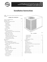
Fig. 2--PHIP018-042/PN2P024-036 Unit Dimensions
128.4 37.02 (940.3)
131.1 39.02 (991.1)
130.2 39.02 (991.1)
132.0 37.02 (940.3)
146.5 37.02 (940.3)
135.6 41.02 (1041.9)
145.2 37.02 (940.3)
148.8 37.02 (940.3)
B. INSPECT SHIPMENT
CENTER OF GRAVITY
IN. (MM)
¥
13.7 (348.0)
13.9 (353.1)
13.7 (348.0)
13.7 (348.0)
14.0 (355.6)
13.7 (348.0)
14.0 (355.6)
14.0 (355.6)
C00137
Z
15.0 (381.0)
15.0 (381.0)
15.0 (381.0)
13.0 (330.2)
13.0 (330.2)
16.0 (406.4)
17.6 (447.0)
16.5 (419.1)
Inspect %r shipping damage while unit is still on shipping pallet. If unit appears to be damaged or is torn loose fi'om its anchorage, have it examined
by transportation inspectors before removal Fmavard claim papers directly to transportation company Manuf_mtmer is not responsible [br any
damage incun'ed in transit. Check all items against shipping list. Immediately notif) the nearest Payne Air Conditioning office if any item is
missing. To prevent loss or damage, leave all parts in original packages until installation.
PROCEDURE 2--PROVIDE UNIT SUPPORT
A. ROOF CURB
Install accesso W roof curb in accordance with instructions shipped with curb (See Fig 5) Install insulation, cant strips, roofing, and flashing_
Ductwork must be attached to curb
IMPORTANT: The gasketing of the unit to the roof curb is critical for a watertight seal, Install gasketing material supplied with the roof curb,
Improperly applied gasketing also can result in air leaks and poor unit performance.
3

t TOP VIEW
REtiRED CLEARAr_ES TO COMBJSTIBLE MATL
MIllIMETERS [IN]
TOP OF UNIT ............................................. 355¸0 [1400]
DUCT SIDE OF UNIT .... S0 8 [200]
S!DE OPPOSITE OUCIS ..................................... 355¸0 [1400]
BOTTOM OF UNIT ........................... {27 (050]
ELECTRIC _EAT PANEL ...................................... 9[4¸4 [30001
NEC. REQUIRED CLEARANCE&
M_LLiMEEERS [IN]
BETWEEN UNITS, POWER ENTRY SIDE ........... 10668 I4E00]
UNIT AND UNGROUNOED SURFACES, POWER ENTRY SlOE .......... 914¸0 [3600]
UNIT AND BLOCK OR CONCRETE WALLS AND OTNER
GROUNDED SURFACES, POWER ENTRY SIDE .................. 1066¸8 [4200]
7
4020
[15631
J
[4 631
88 5
{3 48}
.........lITIl 'ffTT
IIIIIlllIllllllIl
SUPPL? • RETURN
DQCT DUCT
OPENING • OPENING
[13 831 {13 6/] [13 8_]
REAR VIEW
REQUIRE_ CLEARANCE FOR OPERATION AND SERVICING
MILLIMETERS [IN1
EVAP COIL ACCESS SIDE .................................. 9140 [36001
POWER ENTRY SIDE .............. 914 0 [36 001
{EXCEPT FOR NEC REOUIREMENIS}
UNIT TOP ............................. 9140 [36001
SIDE OPPOSITE DUCTS .................................... 9140 [3600]
OUCT PANEL .............................................. 3048 [1200],
,M]N!M_M D_STANBES;W UNI[ IS PLACED LESS IHAN 3048 [IRO0] FROM WALL
STSTEM,TREN SYSTEM PERFORMANCE MAYBE COMPROMISED¸
DIMENSIONS IN [1 ARE IN INCHES
UNIT
PN1P048
PN1P060
PN2P042
PN2P048
PN2P0$0
1090 6
[42 94/
F£LD ENTRY_
SERVICE PORTS
h
]
{47 00]
.....T
I IItlllllIIIlIIIIll
z
__LL_____ ±
12Z_ 3
.......................................... 1{234 ............................................... _ 148 28]
[44 22] \_
\ORAIN OUTLET
_90 [075] NPT
LEFT SIDE VIEW ,,,o_o,.D, FRONT VIEW
445
POWER
222 [o 88] O{A ilOL[_
CONTROL EN#RY
13 431
_222 _"
[48}]
•%
...... 50
{020}
RIGHT SIDE VIEW
_=LECTRBCAL CNARACTr=R_STICS
208/230-1-60, 208/230-3-60, 460-3-60
208/230-1-60, 208/230-3-60, 460-3-60
208/230-1-60, 208/230-3-60, 460-3-60
208/230-1-60, 208/230-3-60, 460-3-60
208/230-1-60, 206/230-3-60, 460-3-60
UNIT WEIGNT
Ib kg
353 160.1
418 189.6
350 158.8
315 170.1
428 194.1
UNIT HEIGHT
IN. {MM)
_A_
38.98 (990.2)
38.98 (990.2)
40.98 (1040.9)
40.98 (I040.9)
42.98 (1091.7)
X
19.9 (505.5)
19.9 (505.5)
19.9 (505.5)
19.9 (505.5)
19.9 (505.5)
Units shown with Optional Field Installed Wire Grilles
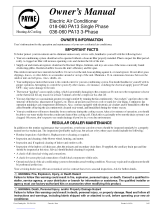
Fig, 3--PNIP048-060/PHEP042-060 Unit Dimensions
CENTER OF GRAVITY
IN.(NM)
Y
15.7 (398.8)
15.7 (398.8)
15.7 (398.8)
15.7 (398.8)
15.7 (398.8)
C00136
Z
17.0 (431.8)
17.0 (431.8)
16.6 (421.6)
18.0 (457.2)
17.6 (447.0)
Curb should be level to within 1/4 in. (See Fig. 6). This isnecessary %r unit drain to _hnction properly. Refer to accessory- roof curb installation
instructions fbr additional infbrmation as required
B. SLAB MOUNT
Place the unit on a solid, level concrete pad that is a minimum of" 4 in tl-gick with 2 in. above grade (See Fig. 7) The slab should extend
approximately 2 in beyond the casing on all 4 sides of the unit Do not secure the unit to the slab except when required by local codes.
C. GROUND MOUNT
The unit may be installed either on a slab or placed directly on the ground if total codes permit Place the unit on tevel ground prepared with gravel
fbr condensate discharge, 4

1 2
Y
4 x 3
o
i
o
CORNER WEIGHTS (SMALL CABINET)
Unit 18 24 30 36 42
Total Weight 283 289 287 291 323
Corner Weight 1 65 67 66 67 83
Corner Weight 2 53 56 54 55 55
Corner Weight 3 61 62 62 63 78
Corner Weight 4 103 104 105 106 107
CORNER WEIGHTS {Small Cabinet_
Yota_ Weidht 999 320 32_ -- --
Corner Weiqht 1 63 63 64 -- --
Corner Weight 2 62 74 76 -- --
Corner Weight 3 56 56 58 -- --
Corner Weight 4 118 127 130 -- --
Fig. 4--Corner Weights
CORNER WEIGHTS (LARGE CABINET)
Unit 48 60
Total Weig ht 353 418
c_ Corner Weight 1 76 90
Corner Weight 2 49 58
"O
O
:_ Corner Weight 3 96 114
Corner Weight 4 132 156
PROCEDURE 3--PROVIDE CLEARANCES
C00071
CORNER WEIGHTS (Lame Cabinet_
_tnit 47 4,_ 60
o_ Yet_t W_ir_ht 350 375 428
oJ
!
m. Corner Weiaht 1 75 81 92
_ Corner Weight 2 49 52 60
O
:_ Corner Weight 3 95 102 116
Corner Weight 4 131 140 160
in Pounds)
The required minimum service clearances are shown in Figs. 2 and 3. Adequate ventilation and outdoor air must be provided. The outdoor fire
&aws air through the outdoor coil and discharges it through the top fun grille. Be sure that the fan discharge does not recirculate to the outdoor
coil. Do not locate the unit in either a comer or under an overhead obstruction. The minimum clearance under a partial overhang (such as a no*real
house overhang) is 36 in. above the unit top. The maximum horizontal extension of a partial overhang must not exceed 48 in. For extended
overhangs, provide a minimum clearance of 48 in
mMPORTANT: Do not restrict outdoor airflow. An air restriction at either the outdoor-air inlet or the fan discharge may be detrimental to
compressor life.
Do not place the unit where water, ice, or snow from an overhang or roof will damage or flood the unit. Do not install the unit on carpeting or
other comhustible materials. Slab-mounted units should be at least 4 in. above the highest expected water and runoff levels. Do not use unit if it
has been under water.
PROCEDURE 4--RIG AND PLACE UNmT
Rigging and handling of d_is equipment can be hazardous %r many reasons due to the installation location (roofs, elevated structures, etc.)
Only trained, qualified crane operators and ground support staff should handle and install this equipment
When working with this equipment, observe precautions in the literature, on tags, stickers, and labels attached to the equipment, and any other
safety precautions that might apply.
Follow all applicable safety codes. Wear safety shoes and work gloves.
A. mNSPECTION
Prior to initial use, and at monthly intervals, all rigging brackets and straps should be visually inspected for any damagQ evidence of wear,
structural defbm_atiom or cracks. Particular attention should be paid to excessive wear at hoist hooking points and load support areas. Brackets
or straps showing any kind of wear in these areas must not be used and should be discarded.
B. mNSTALLATION
1. Remove unit from shipping carton Leave top shipping skid on the malt as a spreader bar to prevent the rigging straps from damaging the
unit If the wood skid is not available, use a spreader bar of sufficient length to protect unit f?om damage.
2 Position the lifting bracket assembly around the base of the unit. Be sure the strap does not twist
3 Place each of the 4 metal lifting brackets into the rigging holds in the composite pan
5

Roof Curb for Small Cabinet
Note A: When unit mounting screw is used,
retainer bracket must also be used
Roof Curb for Large Cabinet
Note A: When unit mounting screw is used,
retainer bracket must also be used
(/125 5mrr)
R/A
\ _ Gasket around_,
duct
\
\ /
\
\\ /
S/A
/2
Insulated Gasket around
deck pan outer edge \
\\\
UNIT SIZE
PH1P018-042 PH2P024-036
PH1P048-060 PH2P042-060
NOTES:
1 Roof curb must be set up for unit being installed.
ODS CATALOG NUMBER
CPRFCURB006A00
CPRFCURB007A00
CPRFCURB098A00
CPRFCURB009A00
A
IN. (MN)
8 (203)
14 (356)
8 (203)
14 (356)
B
IN. {MM)
11(279)
11(279)
16 3/16 (411)
16 3/16 (411)
C
IN. (MM)
161/2 (419)
161/2 (419)
17 3/8 (441)
17 3/8 (441)
C00076
D
IN. (NM)
28-3/4 (730)
28-3/4 (730)
40-1/4 (1022)
40-1/4 (1022)
2 Seal strip must be applied, as required, to unit being installed.
3 Dimensions in ( ) are in millimeters
4 Roof curb is made of 16-gage steel.
5 Table lists only the dimensions, per part number, that have changed.
6 Attach ductwork to curb (flanges of duct rest on curb)
7 Insulated panels: i-in thick fiberglass 1 Ib density
8 Dimensions are in inches
9 When unit mounting screw is used (see Note A), a retainer bracket must be used as well This bracket must also be used when required by code for hurricane or seismic
conditions This bracket is available through Micrometl.
Fig. 5--Roof Curb Dimensions
4. Thread lifting bracket strapping around bottom perimeter of unit as %ltows:
a Open lever of tension buckle (ratchet type)
b. Feed strapping through tension buckle as shown in Fig 8
c Pull strapping through tension buckle unit taut.
d. Snap lever down to lock strap in tension buckle To release strapping, squeeze safety latch, lift lever, and pull webbing outward.
5. Tighten the tension buckle until it is taut Lifting brackets must be secure in the rigging holds.
d. Attach fieldosupplied clevis or hook of sufficient strength to hole in the lifting bracket (See Fig. 9).
d

C
MAXIMUM ALLOWABLE
DIFFERENCE (in)
A-B B-C A-C
1/4 1/4 1/4
Fig. 6--Unit Leveling Tolerances
C99065
I- IIIII
I lllll
I lllll
I
2" I
±I
L
EVAP.COIL
COND. COIL
Fig. 7--Slab Mounting Detail
C99096
HANDHOLD
/
/
/
HOOK _ ....
FEED m_I_
C99067
Fig. 8--Threading Belt
7 Attach the 2 safety straps directly to the clevis or hook at the 4 rigging brackets DO NOT attach the safety straps to the
lifting brackets (See Fig. 9)
g Position lifting point directly over the unit's center of gravity
9. Lift unit. When unit is directly over the roof curb, remove the 2 safety straps. Lower the equipment onto the roof curb.
PROCEDURE 5--SELECT AND BNSTALL DUCTWORK
The design and installation of the &/ct system must be in accordance with the standards of [l_e NFPA [br installation of non-residence type air
conditioning and ventilating systems, NFPA 90A or residence type, NFPA 90B and/or local codes and ordinances.
Select and size ductwork, supply=air registers, and remm air grilles according to ASHRAE (American Society of Heating, Refrigeration, and Air
Conditioning Engineers) recommendations.
The unit has duct flanges on the supply- and return-air openings on the side of the unit.
When designing and installing ¢lt/ctwork_ consider the following:
z_ WARNING: For vertical supply and return units, tools or parts could drop into ductwork and cause serious injury or
death. Install a 90 degree turn in the return ductwork between the unit and the conditioned space. If a 90 degree elbow cannot
be installed, then a grille of sufficient strength and density should be installed to prevent objects from falling into the
conditioned space. Units with electric heaters require 90 degree elbow in supply duct.
1. All units shonld have field=supplied filters or accessory filter rack installed in the return-air side of the unit. Recommended sizes %r filters
are sho_xn in Tables 1 and 2
2. A_oid abla/pt duct size increases and reductions. Abrupt change in duct size adversdy affects air performance.
7

DETAIL A
SCALE 0250
TIGHTEN STRAPPING SECURBL:Y
WITH TENSION SUCKLE
/
SEE DETAIL A
INSTALL SAFETY STRAPS TO
RIGGING CLEVIS AT 4 RIGGING BRACKETS
PLACE RIGGING BRACKET ASSEMBLY IN 4
RIGGING HOLES AND INSTALL TIE DOWN STRAP
AROUND PERIMETER OF UNIT AND THROUGH
SPACE IN BRACKET ASSEMBLY
C99075
MAXIMUM WEIGHT
UNiT A B
{INCLUDES SHIPPING SKID)
Size Ib kg in. mm. in. mm.
PH1P018 305 138.4 19.5 495.3 16.75 425.5
PH1P024 311 141.1 18.5 469.9 16.75 425.5
PH1P030 309 140.2 19.5 495.3 17.50 444.5
PH1P036 313 142.0 19.5 495.3 17.75 459.9
PH1P042 345 156.4 19.5 495.3 17.75 450.9
PH1 P048 375 170.1 20.5 520.7 20.62 523.8
PH1P0$0 440 199.6 19.5 495.3 19.75 501.7
PH2P024 321 145.6 19.0 482.6 18.25 463.6
PH2P030 342 155.2 20.0 508 19.25 489
PH2P036 350 158.8 20.0 508 19.0 482.6
PH2P042 372 168.8 21.0 533.4 20.5 520.7
PN2P048 377 171.0 20.0 508 21.25 539.8
PN2P0g0 450 204.2 21.0 533.4 20.0 508.0
Fig. 9--Suggested Rigging
mNPORTANT: /se flexible connectors between ductwork and m_it to prevent tlansmission of vibration./se s_/itable gaskets to ensure weather
tight and airtight seal When electric heat is installe& use fireproof canvas (or similar heat resistant material) connector between ductwork and unit
discharge connection. If flexible duct is used, insert a sheet metal sleeve inside duct. Heat resistant duct connector (or sheet metal sleeve) must
extend 24-in. from electric heater element.
3. Size ductwork for cooling air quantity (cfm). The minimum air quantity' %r proper electric heater operation is listed in Tables 3 and 4. Heater
limit switches may trip at air quantities below those recommended.
4. Seal, insulate, and weatherproof all external ductworlc Seal, insulate and cover with a vapor barrier all ductwork passing through
conditioned spaces. Follow latest Sheet Metal and Air Conditioning Contractors National Association (SMACNA) and Air ( onditioning
Contractors Association (AC(A) minimum installation standards for residential heating and air conditioning systems.
5. Secure all ducts to building stlucmre. Flash, weatherproo£ and vibration-isolate duct openings in wall or roof according to good construction
practices.
A, CONVERTING HORIZONTAL DISCHARGE UNITS TO DOWNFLOW (VERTICAL) DISCHARGE UNITS
Z_ WARNING: Before performing service or maintenance operations on system, turn off main power to unit and install
lockout tag. Turn off accessory heater power switch if applicable. Electrical shock could cause serious injury or death.
1. Open all electrical disconnects and install lockout tag be%re starting any service work.
2. Remove side duct covers to access bottom return and supply knock outs.
NOTE: These panels are held in place with tabs similar to an electrical knockont.
3. Use a screw&iver and hammer to remove the panels in the bottom of the composite unit base
4. Ensure the side duct covers are in place to block off the horizontal air openings.
8

Fig.10--TypicalInstallation
NOTE:Avoidab_/ptductsizeincreasesandreductions,Abruptchangeinductsizeadveiselya_:_ctsairper%m_ance
PROCEDURE6--PROVBDEFORCONDENSATEDISPOSAL
NOTE:Ensurethatcondensate-waterdisposallllethodscomplywithlocalcodes,restrictions,andpractices.
C00139
Horizontal Duct Covers
Fig, 11--PH2P with Duct Covers On
C99030
The units dispose of condensate through a 3/4 in. NPT female fitting that exits on the compressor end of the unit Condensate water can be &ained
directly onto the roof in toot'top installations (where permitted) or onto a gravel apron in ground level installations. Install a field=supplied
condensate trap at end of condensate connection to ensure proper drainage. Make sure that the outlet of the trap is at least 1 in. lower than the
&ain-pan condensate connection to prevent the pan l:i'om overflowing. Prime the a'ap with water. When using a gravel apron, make sure it slopes
away fi'om the unit.
If the installation requires draining the condensate water away fi'om the unit. install a field=supplied 2=in. tIap at the condensate connection to
ensure proper drainage. (ondensate trap is available as an accessoE¢ or is field-supplied. Make sure that the outlet of the trap is at least 1 in. lower
than the unit &ain-pan condensate connection to prevent the pan t'rom overflowing. Connect a drain trough using a mininmna of field=supplied 3/4
-in. PVC or field-supplied 3/4 -in. copper pipe at outlet end of the 2 =in. trap (See Fig. 12). Do not undersize the robe. Pitch the drain trough
downward at a slope of at least 1 in. ever}' 10 it. of horizontal run. Be sure to check the &ain trough for leaks. Prime the tIap at the beginning
of the cooling season start-up.
1" (25ram) MIN.
TRAP
2" (50ram) MIN.
Fig. 12--Condensate Trap
C99013
9

Table l--Physical Data
UNIT SIZE PH1PO18 PH1PO24 PH1PO3O PH1P036 PH1PO42 PN1PO48 PH1POG0
NOMINAL CAPACITY (ton) 1-1/2 2 2-1/2 3 3-1/2 4 5
OPERATBNG WEBGBT (_b.) 283 289 287 291 323 353 418
COMPRESSOR QUANTITY 1
TYPE RECIPROCATING COMPRESSOR SCROLL COMPRESSOR
REFRIGERANT R-22
REFRIGERANT METERING DEVICE AccuRater@
Refrigerant {R-22) Quantity (_b.) 6.5 5.3 5.6 7.6 8.0 7.85 9.3
ORIFICE ID (in.) 0.053 0.061 0.068 0.078 0.078 0.088 0.093
ORBFIOE OD (in.) 0.040 0.035 (2) 0.042 (2) 0.046 (2) 0.052 (2) 0.057 (2) 0.061 (2)
OUTDOOR COBL
1...17 1...17 1...17 2._17 2._17 2._17 2._17
Rows... Fins/in.
10.2 12.0 12.0 10.3 10.3 11.6 11.6
Face Area (sq. ft.)
OUTDOOR FAN
2400 2400 2400 2800 2400 3300 3300
Nomina_ Airflow (CFM) 22 22 22 22 22 22 22
Diameter
1/8 (825) 1/8 (825) 1/8 (825) 1/4 (1100) 1/8 (825) 1/4 (I100) 1/4 (1100)
Motor HP (RPM)
INDOOR COiL
2._15 2._15 3...15 3._15 4...15 3...15 4...15
Rows... Fins/in.
3.7 3.7 3.7 3.7 3.7 4.7 4.7
Face Area (sq. ft.)
iNDOOR BLOWER
700 800 1000 1200 1250 1600 2000
Nomina_ Airflow (CFM) 10X10 10X10 10X10 11X10 11X10 11X1O 11X10
Size (in.) 1/8 (1075) 1/4 (1075) 1/4 (1075) 1/2 (1075) 3/4 (t075) 3/4 (I075) 1 (1100)
Motor NP (RPM)
RETURN-AIR FBLTERS (in.) 20X20Xl 20X20X1 20X20X1 20X24X1 24X30X1 24X30Xt 24X30X1
throwaway
Tabme 2--Physical Data
UNiT SIZE PN2P024 PN2P030 PH2P036 PH2P042 PN2P648 PN2P660
NOMINAL CAPACBTY (ton) 2 2-1/2 3 3-1/2 4 5
OPERATING WEIGHT (_b.) 299 320 328 350 375 428
COMPRESSOR QUANTITY
TYPE SCROLL COMPRESSOR
REFRIGERANT R-22
REFRIGERANT METERING DEVBCE AccuRater®
Refrigerant {R-22} Quantity (lb.) 5.1 6.4 7.0 10.8 10.1 12.3
ORBFICE ID (in,) 0.065 0.073 0.076 0.080 0.088 0.093
ORBFICE OD (in.) 0.037 (2) 0.043 (2) 0.040 (2) 0.052 (2) 0.057 (2) 0.063 (2)
OUTDOOR COIL
1._17 2...17 2._17 2._17 2._17 2...17
Rows... Fins/in.
13.7 10.3 10.3 13.7 13.7 15.7
Face Area (sq. ft.)
OUTDOOR FAN
2350 2350 2800 2800 3300 3300
Nominal Airflow (CFM) 22 22 22 22 22 22
Diameter
1/8 (825) 1/8 (825) 1/4 (1100) 1/8 (825) 1/4 (1100) 1/4 (1100)
Motor BP (RPM}
INDOOR CO_L
3...15 3...15 4...15 4._15 4...15 4...15
Rows... Finstin.
3.7 3.7 3.7 4.7 4.7 5.7
Face Area (sq. ft.)
iNDOOR BLOWER
800 1600 1200 1400 1450 1750
Nominal Airflow (CFM) 1OX1O 1OX1O 10XI0 11X10 11X1O 11X1O
Size (in.)
Motor HP (RPM) 1/4 (1075) 1/4 (1075) 1/2 (1075) 1/2 (1075) 1/2 (1075) 1 (1040)
RETURN-AIR FILTERS (in.) 20X2OX1 20X2OX1 20X24X1 24X30X1 24X30X1 24X30X1
throwaway
NOTE: Air filter pressure drop for non-standard filters must not exceed 008 in wg.
Table 3--Minimum Airflow for Reliable Electric Heater Operation (Cfm)
AIRFLOW(CFM)I 660 600 1000" 1206 I 1400 I 1600 I 20OO
The 030 size models must be run on medium or high speed when used in conjunction with 15 kw electric heat accessory
]0

Table 4--Minimum Airflow for Reliable Electric Heater Operation (Cfm)
sBzE l P.2Po24 P.2PoaoI P.2Poa6n PH2P042n P.2PO48U P.2PO6O
[ AI*FLOW(CFM)n S00 1000" I 1200 U 1400 1600 [ 200O
* The 030 size models must be run on medium or high speed when used in conjunction with 15 kw electric heat accessory
PROCEDURE 7--BNSTALL ELECTRICAL CONNECTIONS
Z_ WARMNG: The unit cabinet must have an uninterrupted, unbroken electrical ground to minimize the possibility of
personal injury if an electrical faumtshould occur. This ground may consist of an electrical wire connected to the unit ground
lug in the controJ compartment, or conduit approved for electrical ground when instalmed in accordance with NEC, ANS[/NFPA
American National Standards Institute/National Fire Protection Association {latest edition) (in Canada, Canadian Electrical
Code CSA C22.1) and local electrical codes. Failure to adhere to this warning could result in serious injury or death.
Z_ CAUTION: Failure to follow these precautions could resuR in damage to the unit being installed:
1. Make aH electrical connections in accordance with NEC ANSI/NFPA (latest edition) and local electricam codes governing
such wiring. In Canada, aH electricam connections must be in accordance with CSA standard C22.1 Canadian Electrical
Code Part 1 and applicable Bocal codes. Refer to unit wiring diagram.
2. Use only copper conductor for connections between field-supplied electrica! disconnect switch and unit. DO NOT USE ALUMINUM
WIRE.
3, Be sure that high-voltage power to unit is within operating voltage range indicated on unit rating plate. On 3°phase units, ensure
phases are balanced within 2 percent. Consult local power company for correction of improper voltage and/or phase imbalance.
4, Insulate low-voltage wires for highest voltage contained within conduit when low-voltage control wires are in same conduit as
high-voltage wires.
5, Do not damage internal components when drilling through any panel to mount electrical hardware, conduit, etc,
A. HGH-VOLTAGE CONNECTIONS
The unit must have a separate electrical service with a _ield-supplied., waterproof disconnect switch mounted at, oi"within sight flora the uniL Refer
to the unit rating plate, NEC and local codes for maximum f_/seicircuit breaker size and minimum circuit amps (ampacity) for wire sizing (See
Tables 5 and 6 for electrical data).
The field-supplied disconnect may be mounted on the unit over the high-voltage inlet hole (See Fig 2 and 3).
If the unit has an electric heater, a second disconnect may be required. Consult the Installation, Start=Up, and Service Instructions provided with
the accessory fbr electrical service connections.
Operation of unit on improper line voltage constitutes abuse and may cause unit damage that could aft'oct wa_Tanty.
B. ROUTING POWER LEADS BNTO UNBT
Use only copper wire between disconnect and unit. The high=voltage leads should be in a conduit until they enter the duct panel; conduit
termination at the duct panel must be watertight. Run the high-voltage leads through the power entry knockout on the power entry side panel See
Fig. 2 and 3 t'or location and size. When the toads are inside the unit, run leads up the high-voltage raceway to d_e tine wiring splice box (See Fig
13 19) For single-phase units, connect leads to the black and yellow wires; for 3=phase units, connect the leads to the black, yellow, and blue wires
(See Fig 18)
©
©
©
©___
THERMOSTAT
AND SUBBASE
L_
Li
L_
1__
UNIT CONTROL POWER
SPLICE BOX
C99056
Fig. 17--Control Connections
C. CONNECTING GROUND LEAD TO GROUND LUG
Connect the ground lead to the chassis using the ground tug in the wiring splice box (See Fig. 18)
D. ROUTING CONTROL POWER W_RES {24-V)
Form a dripqoop with the thermostat leads before routing them into the unit Route [he thermostat leads through grommeted, tow-voltage hole
provided in unit into unit control power splice box (See Fig. 2 and 3) ( onnect thermostat leads to unit control power tends as shown in Fig 17
11

UNIT PH1P
SIZE
018
O24
O3O
036
O42
048
060
V-PN-HZ
208/230-1-60
208/230-1-60
208/230-1-60
VOLTAGE
RANGE
MIN MAX
187 253
187 253
187 253
Table 5--Electrical Data--PHIP
COMPRESSOR ELECTRIC NEAT
RLA LRA
90 48
128 61
OFM IFM
147 82
208/230-3-60 187 253 99 78 0.9 2.0
208/230-1-60
208/230-3-60
460-3-60
208/230-1-60
2081230-3-60
460-3-60
208/230-1-60
187 253
187 253
414 506
187 253
187 253
414 506
187 253
187 253
414 506
187 253
187 253
414 506
2081230-3-60
460-3-60
208/230-1-60
168 82
99 85
55 40
206 115
124 90
67 45
244 140
141 105
71 53
288 165
194 125
80 63
208/230-3-60
FLA FLA Nominal
Kw*
3.8/50
0.9 1.8
5.4/72
75/10.0
4-
3.8/50
0.9 2.0
5.4/72
75/10.0
4-
3.8/50
0.9 2.0 5.4/72
75/10.0
11.3/15.0
4-
3.8/50
75/10.0
11.3/15.0
4-
3.8/50
1.5 4.1 5.4/72
75/10.0
11.3/15.0
4-
3.8/50
1.5 4.1
75/10.0
11.3/15.0
5
0.8 19
10
15
3.8/50
5.4/72
0.9 38
75/10.0
11.3/15.0
15.0/20.0
4-
3.8/50
0.9 3.8 75/10.0
11.3/15.0
15.0/19.9
5
0.8 18 10
15
20.0
4-
3.8/50
5.4/72
1.5 35
75/10.0
11.3/15.0
15.0/19.9
4-
3.8/50
1.5 35 75/10.0
11.3/15.0
15.0/20.0
5
0.8 18 10
15
2O
3.8/50
5.4/72
1.5 62
75/10.0
11.3/15.0
15.0/20.0
4-
3.8/50
1.5 62 75/10.0
11.3/15.0
15.0/19.9
5
0.8 3.2 10
15
2O
FLA
-/-
181/208
260/300
361/417
4-
181/208
260/300
361/417
4-
181/208
260/300
361/417
542/625
4-
104/12 0
208/241
313/361
4-
181/208
260/300
361/417
542/625
-p
104/120
31 3/361
361/417
-p
6.0
120
180
4-
181/208
260/300
361/417
542/625
722/833
-p
104/120
208/241
31 3/361
41 6/480
-p
6.0
120
180
241
4-
181/208
260/300
361/417
542/625
722/833
-p
104/120
208/241
313/361
41 6/480
6.0
120
180
241
4-
181/208
260/300
361/417
542/625
722/833
4-
104/120
208/241
31 3/361
41 6/480
6.0
120
180
241
FUSE OR
MCA
CKT BKR
14.0/140 20/20
36.5/400 40/45
46.4/51 5 50/60
59.1/660
18.9/189 25/25
41.5/449 45/45
51.4/564 60/-
64.0/71 0
21.3/21 3 25/25
43.8/473 45/50
53.8/588
66.4/734
89.0/994
15.3/153 20/20
28.3/303 30/35
41.3/453 45/50
54.4/604 60/-
26.6/266
35/35
49.2/526
50/60
59.1/641
71.7/787
94.3/1047
18.0/180 25/25
31.0/330 35/35
44.0/480 45/50
57.1/631 60/-
9.6 15
17.1 20
24.6 26
32.1 35
30.5/305 40/40
53.0/565 60/60
62.9/680
75.6/825
98.1/1086
120.7/134.6
20.2/202 26/25
33.2/352 40/40
46.3/503 50/60
59.3/653 60/-
72.2/802
11.0 15
18.5 20
26.0 30
33.5 35
41.0 45
35.5/355 45/45
58.1/615
68.0/730
80.6/876
103.2/113.6
125.8/139.7
22.6/226 30/30
35.7/377 40/40
48.7/527 50/60
61.7/677
74.6/826
11.5 15
19.0 20
26.5 30
34.0 35
41.5 45
43.7/437 60/60
66.3/697
76.2/81 2
88.8/958
111.4/121.8
134.0/147.9
32.0/320 40/40
45.0/470 50/50
58.0/62 1
71.1/771
83.9/91 9
14.0 20
21.5 25
29.0 30
36.6 40
44.1 45
460-3-60
SINGLE POINT POWER SUPPLY
MOCP
60/70
-/70
70/80
70/70
70/80
90/100
-/70
70/80
80/80
100/110
-/70
80/90
80/90
100/110
125/150
-/70
80/90
70/70
90/90
90/100
110/125
150/150
70/70
80/90
70/80
100/110
100/110
125/125
150/150
60/70
80/80
90/100
The unit trans%rmer supplies 24-v pox_er %r complete system including accesso_ electrical heater An mltomaticoreset circuit breaker (See Fig
0}
19) is provided in the 24-x circuit; see the caution label on the transformer or Fig. 20. Transformer is factory wired for _30o_ operation, If supply
xoltage is 208=v, rewire trausfi_rmer primaw as described in Special Procedures for 208-v Operatiou section,
12

UNIT PH2P
S_ZE
024
03O
036
042
048
06O
WPH=HZ
208/230-1-60
208/230-1-60
208/230-3-60
208/230-1-60
208/230-3-60
460-3-60
208/230-1-60
208/230-3-60
460-3-60
208/230-1-60
208/230-3-60
460-3-60
208/230-1-60
208/230-3-60
460-3-60
VOLTAGE
RANGE
MIN MAX
187 253
187 253
187 253
187 253
187 253
414 506
187 253
187 253
414 506
187 253
187 253
414 506
187 253
187 253
414 506
TaMe 6--Electrical Data--PH2P
COMPRESSOR ELECTRIC HEAT
OFM
FLA
090
RLA LRA
10.8 56
14.0 73 0.9
10.4 63 0.9
16.7 97 1.6
11.2 75 1.6
54 375 0.9
18.4 104 0.9
12.4 88 0.9
58 44 0.9
23.4 126 1.6
13.0 93 1.6
64 465 0.9
28.8 169 1.4
17.3 123 1.4
_FM
FLA
Nominal Kw _ FLA
4- 4-
3.8/50 181/208
20
5.4/72 260/300
7.5/10.0 361/417
4- 4-
3.8/50 181/208
21 5.4/72 260/300
7.5/10.0 361/417
11.3/15.0 542/625
4- 4-
3.8/50 104/120
21
7.5/10.0 208/241
11.3/15.0 313/361
4- 4-
3.8/50 181/208
36 5.4/72 260/300
7.5/10.0 361/417
11.3/15.0 542/625
4- 4-
3.8/50 104/120
36
7.5/10.0 361/417
11.3/15.0 313/361
-E 4-
5 6
19
10 12
15 18
4- 4-
3.8/50 181/208
5.4/72 260/300
41
7.5/10.0 361/417
11.3/15.0 542/625
15.0/20.0 722/833
4- 4-
3.8/50 104/120
41 7.5/10.0 208/241
11.3/15.0 313/361
15.0/20.0 416/480
-/- 4-
5 6
20 10 12
15 18
20 241
4- -/-
3.8/50 181/208
5.4/72 260/300
41
7.5/10.0 361/417
11.3/15.0 542/625
15.0/20.0 722/830
4- 4-
3.8/50 104/120
41 7.5/10.0 208/241
11.3/15.0 313/361
15.0/20.0 416/480
-/- 4-
5 6
20 10 12
15 18
20 241
4- 4-
3.8/50 181/208
5.4/72 260/300
62
7.5/10.0 361/417
11.3/15.0 542/625
15.0/20.0 722/833
4- 4-
3.8/50 104/120
62 7.5/10.0 208/241
11.3/15.0 313/361
15.0/19.9 416/480
-E 4-
5 6
32 10 12
15 18
20 241
MCA
164/164
390/424
489/539
61 5/685
205/205
431/465
530/580
656/726
882/986
160/160
290/31 0
421/461
551/61 1
261/261
486/521
586/636
71 2/782
938/104.2
192/192
322/342
452/493
583/643
96
171
246
321
280/280
506/540
605/655
731/801
957/106.1
1183/132.2
205/205
335/355
466/506
596/656
725/805
102
177
252
327
402
349/349
574/609
673/724
800/869
1025/113.0
1251/139.0
21 9/21 9
349/369
479/51 9
609/670
738/81 8
108
183
258
333
408
436/436
662/696
761/181.1
887/957
111 3/121.7
1339/147.8
292/292
423/443
552/594
683/743
81 2/892
154
229
304
379
454
SINGLE POINT POWER SUPPLY
MOCP
FUSE OR
CKT BKR
20/20
40/45
60/60
25/25
45/50
20/20
35/35
45/50
35/35
50/60
35/35
50/50
15
2O
25
35
35/35
60/60
25/25
40/40
50/60
15
20
30
35
45
45/45
30/30
40/40
50/60
15
20
3O
35
45
60/60
35/35
50/50
60/60
90 62 0.9
20
25
35
40
50
70/70
70/70
70/80
90/100
60/70
70/80
80/80
100/110
60/70
80/80
80/90
100/110
125/150
60/70
80/90
70/70
90/90
90/90
110/125
150/150
70/70
80/90
70/80
100/110
100/100
125/125
150/150
70/80
90/90
E. SPECIAL PROCEDURES FOR 208-V OPERATION
1 Disconnect the yellow primary lead from the transformer. See unit wiring label (See Fig 13 and 14).
2 Connect the yellow prima W lead to the trans_brmer terminal labeled 200°v,
Indoor blower-motor speeds may need to be changed for 208-v operation, Re_r to indoor airflow and airflow adjustments section,
13

FIELD
MAXIMUM WIRE I _ WlBLK
SIZE 2 AWG _ SUPPLY
i II_I L WR YEL
USED WITH POWER
ACCESSORY EQUIP GND
BLK_
,
NAXWIRE i YEL_
(30 AMP FOR S KW)_
(FUI & FU4)_----
I I BO AMP SB MIR
USED WITH _BLKJ
ACCESSORY
ELECTHEAT I _W
OPTION ONLY I I GO AMP SB HTR:
USED WITH I _ELECT_ YLL
HEATER OPTIONS 60 AMP SB
5NW {048060) F
IOHW (DIS 060> I __BIK
210 MAXWIRE SO AMP SB
_MTPl
GO AMP SB
_TO I
30 AMP SIB. HTR
_TO ,
30 AMP SB Hi_.
60 AMP SB HTRI
50 AMP S IB I
210 MANIWlRE
F7 SCHEMATIC
_ .C,--/ _ IDR _BLK _ 208/230-1-60
_ __,__w_ OLN_OLN _X
[_ __W4 YEL _¢Ap21cAp2 YBERLN_ )OFM
: i
i CCH {50JS036 ONLY) LwY YEL COMP
t BLK _ _W9 BLU_
/___TD_ RED o _&_To_LV)NED SPEED FOR
1"' ,ELo :E:T SmF
cAPSoR;2
_W70 °LK
WIlD YEL_
3.2 AMP
MANUAL RE
_YEL TRANI
HEAT!%{ WOORN_
ZBT SEE NOTE
LW D RED
O"G L
FAN
AUTO sw
?N
"_N THI 0
SUPPL SUPL HEAT E
SUPPL HEAT
FIELD THERMOSTAT
SEE NOTEA2
/-
I
W6 PNN
W72 WHT
W69 VIO
Wl2O GRA
W21BRN
WIIG BRN
:ONNECTION
:OR i []
£LECT HEAT i
DEFROS'_
BOARD
/
SEE HEATER
SCHEMATIC _
FORWIRING
_%SPL,C_
I f
24V SPLICE BOX
UNIT COMPONENT ARRANGEMENT
OUTDOOR FAN
SECTION
COMPRESSOR INDOOR FAN
SECTION SECTION
r_ _....U
50JS048 & 060
R
DEFROST BOARD <DB)
GRN YEL_
GRN YEL
Wll BRN
W12 BRN
PNK_ PNK_
LPS
BLU_ BLU_jI023 BRNBRN
°LK_W23 BRN
z_,P.
_ _-_ECTI
--24V POWER ENTRY
PL I
W12 BRN
ACCESSSORY ELECTRIC HEAT_
HR, EY hrY
[5 NW) Wl23 °RN
116 BRN
HRI & 2 (10 KW)__22 BRN
I
_Wl23 BRN
HRI,2 & 3 (15 KW}_ I 121 °RN
HRI,2,3 & 4 (20 KW)
LEGEND
TDR(I 3) FAN SEQUENCE
FIELD SPLICE AHA ADJU$TABLEHEAT ANTICIPATOR
O TERMINAL [MARKED3 C CONTACTOR
o TERMINAL (UNMARKEDI CAP CAPACITOR
• SPLICE CB CIRCUIT BREAKER
OISPLICE {MARKED3 CCH CRANKCASEHEATER
COMP COMPRESSORMOTOR
FACTORYWIRING ¢TD COMPRESSORTIME DELAY
FIELD CONTROLWIRING DB DEFROSTBOARD
i. FIELDPO_ER WIRING OFT DEFROSTTHERMOSTAT
=ii ACCESSORYOR OPTIONAL DR DEFROSTRELAY
WIRING EOUlP EOUlPMENT
FU FUSE
I TO INDICATECOMMON GND GROUND
POTENTIALONLY: HR HEATERRELAY
NOT TO REPRESENTWIRING HTR HEATER
IFM INDOORFAN MOTOR
LPS LOW PRESSURESWITCH
OFM OUTDOOR FAN MOTOR
QT QUADRUPLETERMINAL
RV_ REVERSINGVALVE SOLENOID
$B, SLOWBLOW FU_E
TC THERMOSTATCOOLING
TDR TIMEDELAY RELAY
TH THERMOSTATHEATING
TRAM TRANSFORMER
I
i _T',O
ENERGIZED DE ENERGIZED
CTD (TI,T2) COMPRESSOR DELAY
I , i i MIIN.
o 5 SECT T+5
CI CI
CLOSES OPENS
TSAT
NOTE_
I_ IF ANY OF THEORIGINALWIRESFURNISHEDARE REPLACED,
IT _U_TBE REPLACED_ITHTYPE_0 DE_REEC _IREOR
IT'SEQUlVALENT_
_ SEE PRICEPAGESFORTHERMOSTATAND SUBBASES_
USE7S DEGREECOPPERCONDUCTORSFORFIEL_ INST_LLATION
4_ FOR HIGH_PEEDIF_,DlSCONNECTRED
*IREFRO_T_R _ ANDCONNECT_LK_IREFBOM IF_
FOR _EDIUMSPEED,DISCONNECTRE__IRE
FRO_TDR _ ANDCONNECTBLU_IRE FRO_IFM_
S_ _EFROSTTIMERTO BESET AT _0MINUTESEXCEPT
FOR 50JSO4aA_ MODELSSET AT _0MINUTES_
CYCLE T:90
15oJ85OOOO516.c
C
Fig, 13--Wiring Schematics (208/230o%60)
00133
14

MAXIMUMWIRE m _Wl BLK
S'ZE2AW°__ W2YEL
I%EOUIP GND Wl2111BLUUSED WITH .....
ACCESSORY
ELECT HEAT m _ _ '
OPTION ONLY L BLK R
USED WITH I_ _TO HT
/
HEATER OPTIC I
5 & IOKW (0_ I
060)
MAXWlRE
2 AWG I
(50 AMP FOR K I
{FL 3 &
USED WITH I
ACCESSORY
ELECTHEAT
OPTION ONLY
USED WITH I
HEATER OPTIC
16 K W (024 060)
19.9 NW {042 060)
2/0 MAXWIRE i
(20 KW SHOWN)
32 AMP CB
MANUAL RESET_[_.._,._,.._W60RN_
LW 3 RED
YEL_
TRANI
RED
YEL
W26
/
ORN YEL_W26 GRN YEL_
GRN YEL GRN YEL
=
SCHEMATIC
208/230-3-60
OFM
COMP
Wll BRN
1
R oN ( I
FAF
ON ON (
"_N THI
SUPPL@_ _$UPL.HEAT _ _
I
SUPPL HEAT
FIELD THERMOSTAT
SEE NOTE#2
GRM
BRN
W120 BRN
24V SPLICE BOX
UNIT COMPONENT ARRANGEMENT
OUTDOOR FAN {OFM_
SECTION
COMPRESSOR INDOOR FAN
SECTION SECTION
Fq
50JXC42 060
rl T2 50JSO4B & 060
r3 /
CONNECT ION
FORELECT HEAT
D
DEFROST
BOARD
/
"_'_F ____.____
[SOJSO36,50JX060 ONLY]
"EQUIP
GND
PLI I
LEGEND
ACCESSORY ELECTRIC HEAT_
_ W12 BRN
HH,
HRI & 2 {10 K__ N
HRI,2 & 3 (15 KW)
,,
HRI 2 3 & 4 (20 KW)_
I
_FIELD SPLICE _HA ADJUSTABLE HEAT ANTICIPATOR
C3TERMINAL (MARKED) CONTACTOR
o TERMINAL CUNMARKED3 CAP CAPACITOR
CB CIRCUIT BREAKER
• SPLICE CCH CRANKCASE HEATER
@SPLICE [MARKED) COMP COMPRESSOR MOTOR
FACTORY WIRING CTP COMPRESSOR TIME DELAY
FIELD CONTROL WIRING DB DEFROST BOARD
ii FIELD POWER WIRING DFT DEFROST THERMOSTAT
111 ACCESSORY OR OPTIONAL DR DEFROST RELAY
WIRING EQUIP EQUIPMENT
FU FUSE
I TO INDICATE COMMON GN_ GROUND
POTENTIAL ONLY: HR HEATER RELAY
NOT TO REPRESENT WIRING HTR HEATER
IFM INDOOR FAN MOTOR
LP3 LOW PRESSURE SWITCH
OFM OUTDOOR FAN MOTOR
QT QUADRUPLE TERMINAL
RW REVERSING VALVE _OLENOID
SLOW BLOW FUSE
_dB"
THERMOSTAT COOLING
TBR TIME DELAY RELAY
TH THERMOSTAT HEATING
TRAN THANSPORMER
1
NOTES:
DISCONNECT I IF ANY OF THE ORIGINAL WIRES FURNISHED ARE REPLACED,
PER NEC7 IT MUST BE REPLACED WITH TYPE _0 DEGREE C _IRE OR
-- _ IT'S EOUIVALENT
2 SEE PRICE PAGES FOR THERMOSTAT AND SUBBASES
--24V POWER ENTRY 3 U_E 75 DEGREE COPPER CONDUCTOR_ FOR FIELD INSTALLATION.
4 FOR HIGH _PEED IFM,#I_CONNEGT RED
WIRE FBOM TDR 3 AND CONNECT BLK WIRE FROM IF_
FOR _EDIUM SPEED,_ISCONNECT RED _IRE
FROMTDR 3 AND CONNECT BLU _IRE FRO_ IFM
DEFROST TI_ER TO BE _ET AT _O _INUTE_ EXCEPT
FOR 50J_04_,060 _ODELS SET AT 5D MINUTES
TDR (I13) FAN SEQUENCE
I
iT'00
ENERGIZED DE ENERGIZED
CTD (TI,TZ) COMPRESSOR DELAY
l'_SEC_ T4M',N
CI CI
CLOSES OPENS
TSAT
ERGIZEm I
Rv_J _ T:30 _+I0 MIN
LAST DFROST TzSO MAXIMUM
CYCLE T:90
Fig. i4--WiMng Schematics (208/230o3o_0)
C00134
15

_Wl RLK
_M_MA%G!E -- iIIF_POWERw2 YE'L
___i w2 0LUl
EQUIP GND
OT .... ! !
ACCESSORY I I_BLK-- J
ELECT HEAT TO HTH
OPTION ONLY I IIHI_
USED WITH I --_YEL
HEATER OPTIONS L TO HTR
5, lO,I5 & 20 KW !_ p
MAXIWlREAwG I _LL BLU L< TO HTR
R ON
L V
SUPPLIHEAT
FIELD THERMOSTAT
SEE NOTE@2
W124 BRN
24V SPLICE BOX
UNIT COMPONENT ARRANGEMENT
OUTDOOR FAN
SECTION
COMPRESSOR INDOORFAN
SECTION SECTION
ZLECTNEAT
r_
COMP
TI T2 S 50JXD42 06O
50J5048 & 06O
T3_.2..__ F
_50JSO36,50JX060 ONLY)
OFR
RED
YEL
--W25 ORN YEL_W26 GRN YEL_
ORN YEL GRN YEL
SCHEMATIC
Wll BRN
W12 BRN
WlO BRN
II BRN
Will BLU_wI09 BRN
LEGEND
ACCESSORY ELECTRIC
HEAT_ W12 BRN
HRI {S KW) I_I17Z4 B_ N
HRI & 2 {10 KW) BRN
NR2SSNW w LNR N
HRI,2,3 & 4 (20 KW)_
[
AHA ADJUSTABLE HEAT ANTICIPATOR
C CONTACTOR
CAP CAPACITOR
CB CIRCUIT BREAKER
CCH CRANKCASE HEATER
CONP COMPRESSOR MOTOR
CTD COMPRESSOR TIME DELAY
DB @EFROST BOARD
DFT DEFROST THERMOSTAT
DR DEFROST RELAY
EQUIP EQUIPMENT
6ND GROUND
HR HEATER RELAY
HTR HEATER
IFM INDOOR FAN MOTOR
LpS LOW PRESSURE SWITCH
OFM OUTDOOR FAN MOTOR
OFR OUTDOOR FAN RELAY
OT QUADRUPLE TERMINAL
RVS REVERSING VALVE SOLENOID
FIELD SPLICE
C>TERMINAL CMARKED3
o TERMINAL (UNMARKED3
• SPLICE
(31SPLICE (MARKED)
FACTORY WIRING
FIELD CONTROL WIRING
1- FIELD POWER WIRING
1.. ACCESSORy OR OPTIONAL
WIRING
I TO INDICATE COMMON
POTENTIAL ONLY:
NOT TO REPRESENT WIRING
_EQUIP TC THEBMOSTATCOOLIN6
GND TDR TIME DELAYRELAY
TH THERMOSTATHEATING
TRAN TRANSFORMER
SEE HEATER
SCHEMATIC I
FORWIRING
DISCONNECT NOTES:I IF ANYOFTHEORIGINALWIRESFURNISHEDAREREPLACED,
...... PERNEC___ IT MUSTBEREPLACED_ITH TYPE9DDEGREEC WIREOR
-- • SEEPRICEPAGESFORTHERMOSTATANDSUBBASES
24V SPLICE --24V POWERENTRY USE_S DEGREECOPPERCONDUCTORSFORFIELD INSTALLATION¸
4 FORNIGHSPEEDIFM,DlSCONNECTRED
WIREFROMTDR3 ANDCONNECTBLKWIREFROMIFM
FORMEBlUMSPEED,DISCONNECTREDWIRE
FROMTDR3 ANDCONNECTBLUWIREFROMIFM.
5 DEFROSTTIMERTOBE SETAT 90 MINUTESEXCEPT
FOR50JSO4B,O_OMODELSSETAT 50MINUTES.
TDR (13) FAN SEQUENCE
I
i 4o0
G
ENERGIZED DE ENERGIZED
CTD [TIT2) COMPRESSOR DELAY
I ; SEC T T+_ MIIN.
Cl CI
CLOSES OPENS
T_AT
CYCLE T:90
Fig. i5--Wiring Schematics (460o3o60)
C00135
16

LEGEND
FLA -- FultLoadAmps
LRA -- LockedRotorAmps 1,_
MCA-- MinimumCircuitAmps
MOCP-- MaximumOvercurrentProtection
RLA -- RatedLoadAmps
CKTBKR-- CircuitBreaker
NOTES:
1.IncompliancewithNEC(NationalElectricalCode)requirements
formultimotorandcombinationtoadequipment(refertoNEC
Articles430and440),theovercurrentprotectivedeviceforthe
unitshallbePowerSupplyfuse.Canadianunitsmaybe
fuseorcircuitbreaker.
2.Minimumwiresizeisbasedon60Ccopperwire.Ifotherthan
60Cwireisused,oriftengthexceedswirelengthintable,
determinesizefromNEC.
3.Unbalanced3-PhaseSupplyVoltage
Never operate a motor where a phase imbalance in supply volt-
age is greater than 2%. Use the following formula to determine
the percentage of voltage imbalance.
% Voltage imbalance
= 100 x max vottage deviation from average voltage
average vottage
EXAMPLE: Supply voltage is 460-3-60.
A B C AB = 452 v
BC = 464 v
AC = 455 v
Average Voltage =
452 + 464 + 455
3
1371
3
= 457
Determine maximum deviation from average voltage.
(AB) 457 452=5v
(BC) 464 457=7v
(AC) 457 455=2v
Maximum deviation is 7 v.
Determine percent of 'voltage imbalance.
7
% Voltage Imbalance = 100 x --
457
= 1.53%
This amount of phase imbalance is satisfactory as it is below the
maximum allowable 2%.
IMPORTANT: If the supply voltage phase imbalance is
more than 2%, contact your local etectric utility company
immediately.
c99024
Fig. 16--Emectrical Data Legend
GROUND LUG
(IN SLPICE BOX
SINGLE-PHASE L1
CONNECTIONS
TO DISCONNECT
PER NEC L2
3-PHASE
CONNECTIONS
LEGEND
GROUND __,_
LEAD
L3 ......
NOTE: Use copper wire only.
NEC - National Electrica! Code
Field Wiring
Spike Connections
Fig. 18--Line Power Connections
PRE-START-UP
C99057
z_ WARNING: Failure to observe the following warnings coumd result in serious personal injury or death:
1. Follow recognized safety practices and wear protective goggles when checking or servicing refrigerant system.
2. Do not operate compressor or provide any electric power to unit unless compressor terminal cover is in place and secured.
3. Do not remove compressor terminal cover until aH electrical sources are disconnected and tagged.
4. Relieve and recover all refrigerant from system before touching or disturbing anything inside terminal box if refrigerant
leak is suspected around compressor terminals.
5. Never attempt to repair soldered connection while refrigerant system is under pressure.
6. Do not use torch to remove any component. System contains oH and refrigerant under pressure.
To remove a component, wear protective goggles and proceed as follows:
a. Shut off electrical power to unit and install mockout tag.
b. Relieve and reclaim aH refrigerant from system using both high- and low-pressure ports.
c. Cut component connecting tubing with tubing cutter and remove component from unit.
d. Carefully unsweat remaining tubing stubs when necessary. OH can ignite when exposed to torch flame.
/se the Start-Up (hecklist supplied at the end of this book and proceed as %llows to inspect and prepare the unit %r initial start-up:
1 Remove access panel,
2 Read and follow instructions on all DANGER, WARNING, (AUTION, and INFORMATION labels attached to, or shipped with, unit,
3 Make the following inspections:
a, Inspect _br shipping and handling damages such as broken lines, loose parts, discom_ected wires, etc,
17

24 V Circuit Breaker -_
24 Volt Compartment
Fig. 19--Control Wiring Plate
C99070
TRANSFORMER CONTAINS A MANUAL
RESET OVERCURRENT PROTECTOR
IT WILL NOT AUTOMATICALLY RESET
DISCONNECT POWER AND INSTALL
LOCKOUT TAG PRIOR TO SERVICING
THIS COMPARTMENT MUST BE CLOSED
EXCEPT WHEN SERVICING
C99058
Fig. 20--Transformer Label
b. Inspect foI oil at all refrigerant tubing connections and on unit base Detecting oil generally indicates a refrigerant leak. Leak-test all
refiigerant robing connections using electronic leak detector, or liquid=soap solution. Ifa ref'rigerant leak is detected_ see following Check
fbr Refiigerant Leaks section.
c. Inspect all field and fhctory=wiring connections. Be sure that connections are completed and tight.
d. Ensure wires do not touch refrigerant robing or sharp sheetmetal edges.
e. Inspect coil fins. If damaged dr/ring shipping and handling, carefhlly straighten fins with a fin comb.
4. Verify the following conditions:
a. Make sure that outdoor-fan blade is correctly positioned in fire orifice (See Fig. 21).
b. Make sure that condensate drain pan and trap are filled with water to ensure proper &ainage.
c. Make sure that all tools and miscellaneous loose parts have been removed.
5. (ompressors are internally spring mounted. Do not loosen or remove compressor holddown bolts.
6. Each unit system has 2 Schrader=type ports, one tow-side Schrader fitting located on the suction tine, and one high-side Schrader fitting
located on the compressor discharge line. Be sure that caps on the ports are tight.
7. High flow valves are located on the compressor hot gas and suction robes. These valves can not be accessed fbr service in the field. Ensure
the plastic caps are in place and tight or the possibility or refi'igerant leakage could occur.
START-UP
l_sing the Start-Up (hecklist supplied at the end of this book, proceed as %llows:
PROCEDURE I--CHECK FOR REFR{GERANT LEAKS
Locate and repair refi'igerant leaks and charge the unit as fbltows:
1. Use both high- and tow-pressure ports to relieve system pressure and reclaim remaining refi'igerant.
2. Repair leak fbltowing accepted practices.
NOTE: Install a bi=flow filter drier whenever the system has been opened for repair.
3. Check system for leaks using an approved method.
18

MOTORANDFANHUB
MOTOR SHAFT
C99009
Fig. 21--Fan Blade Clearance
4 Reclaim refi'igerant and evacuate refl'igerant system to 500 microns if no additional leaks are found
5 Charge unit with R°22 refi'igerant, using a volumetric-charging cylinder or accurate scale. Refer to unit rating plate for required charge. Be
sure to add extra refiigerant to compensate for internal volume of filter drier.
PROCEDURE 2--START-UP ADJUSTNENTS
(omplete the required procedures given in the Pre-Starl=Erp section before starting the unit. Do not jumper any safety devices when operating the
unit. Do not operate the unit in (ooling mode when the outdoor temperature is below 40 _>F (unless accessory tow°ambient kit is installed). Do
not rapid-cycle the compressor. Allow 5 minute between "on" cycles to prevent compressor damage.
A, CHECKING COOLING AND HEATING
CONTROL OPERATION
Start and check the unit _br proper control operation as follows:
1. Place room thet_nostat SYSTEM switch in OFF position. Observe that blower motor starts when FAN" switch is placed in ON position and
shuts down within (50 sec. when FAN switch is placed in AUTO position.
2. Place SYSTEM switch in COOL position and FAN switch in AUTO position. Set control below room temperature. Observe that cooling
cycle shuts down when control setdng is satisfied.
3. Place system switch in HEAT position. Set control above room temperature. Observe that compressor, outdoor tim, and indoor blower
motors start. Observe that heating cycle shuts down when control setting is satisfied.
4. When using an atttomatic changeover room thermostat, place both SYSTEM and FAN" switches in AUTO positions. Observe that unit
operates in Cooling mode when temperatme control is set to "call for Cooling" (below room temperature), and unit operates in Heating
mode when temperature control is set to "call for Heating" (above room telaperamre).
IMPORTANT: ThreeophasQ scroll compressors are direction oriented. Unit must be checked to ensure proper compressor 3-phase power lead
orientation. If not corrected within 5 minute, the internal protector will shut off the compressor. The 3-phase power leads to the unit must be
reversed to cot_vct rotation. When turning backwards, scroll compressors emit elevated noise levels, and the difference between compressor suction
and discharge pressures may be dramatically lower than normal.
B. CHECKING AND ADJUSTING REFRIGERANT CHARGE
The refrigerant system is fldly charged with R-22 re['rigerant and is tested and fhctory sealed. Allow system to operate a minimum of 15 minutes
bel:bre checking or adjusting charge.
NOTE: Adjustment of the refl'igerant charge is not required unless the unit is suspected of not having the proper R-22 charge. The charging label
and the tables shown re_hr to system temperatures and pressures in cooling mode only. A refiigerant charging label is attached to the outside of
the service access door. If charge level is suspect in Heating mode, reclaim all re['rigerant and charge to nameplate amount. (This inJ:brmation may
be obtained from the physical data table also.)
IMPORTANT: When evaluating the refi'igerant charge, an indicated adjustment to the specified _i_ctoV charge must always be ve_- minimal. If
a substantial adjustment is indicated, an abnom_al condition exists somewhere in the cooling system, such as insu_l]cient airflow across either coil
or both coils.
C. REFRIGERANT CHARGE
The amount of refligerant charge is listed on the unit nameplate and/or the physical data table. Refer to the Refi'igeration Service Techniques
Manual Refi'igerants Section.
D, NO CHARGE
Check for leak. Use standard evacuating techniques, After evacuating system to 500 microns_ weigh in the specified amount of refrigerant (refer
to system data plate)
E. LOW CHARGE COOLmNG
Lse (ooling (harging Charts (Fig. 26-38) Va_- refi'igerant until the conditions of the chart are met Note that charging charts are different fiom
type normally used. (harts are based on charging the units to cot_'ect superheat for the various operating conditions Accurate pressure gage and
temperature sensing devices are required. ( onnect the pressure gage to the service port or* the suction line. Mount the temperature sensing device
on the suction tine and insulate it so that the outdoor ambient does not affect the reading, Indoor air CFM must be within the normal operating
range of the unit
g. TO USE COOLmNG CHARGING CHARTS
qake the outdoor ambient temperature and read d_e suction pressure gage. Refer to the chart to determine what the suction temperature shouk! be.
NOTE: [f the problem causing the inaccurate readings is a refi'igerant leak, refer to Check _br Refrigerant Leaks section.
19

OUTDOOR COIL
LEGEND
HPS - High Pressure Switch
LCS - Loss of Charge Switch
Accurate€' Metering Device
Arrow indicates direction of flow
Metering
Position
Bypass
Position
INDOOR COIL
Fig. 22--Typical Heat Pump Operation, Heating Mode
LEGEND
HPS - High Pressure Switch
LCS - Loss of Charge Switch
Accurate€" Metering Device
[_ Arrow indicates direction of flow
OUTDOOR COIL
1T
Bypass
Position
Meterh/g
Position
INDOOR COIL
Fig. 23--TypicN Heat Pump Operation, Cooling Mode
C00095
C00096
G. INDOOR AIRFLOW AND A_RFLOW ADJUSTMENTS
z:_ CAUTBON: For heating and cooling operation, the recommended airflow is 350 to 450 cfm for each 12,000 Btuh of rated
cooling capacity. For units with optional electric heat, the airflow must not be reduced bemow the levels stated in TaMes 3 and
4. Failure to maintain these airflows coumd resumt in damage to the unit.
Tables 7 and g shows both heating and cooling airflows at various external static pressures Refer to these tables to detem_ine the airflow %r the
system being installed.
NOTE: Be sure that all supply-and return-air grilles are open, tiee fi'om obstructions, and adjusted properly
Airflow can be changed by changing the lead connection of the blower motor.
Unit PHIP and PH2P three-speed motors (except sizes PH1P 018 and PH2P 030) are factory wired for tow speed operation Unit PH2P 030 is
_actory wired for medium speed. Unit PHIP 018 has a two-speed motor wired for tow speed
For 208/230-v Motors: The motor leads are color-coded as follows:
3-SPEED
Black high speed
Blue medium speed
Red low speed
To change the speed of the indoor fhn motor (IFM), remove the _hn motor speed leg lead fi'om d-_eTime Delay Relay (TDR) This wire is attached
to TDR-3 fbr single-phase and 3-phase malts. To change the speed, remove and replace with lead for desired blower motor speed, i_s_date the
removed lead to avoid contact with chassis parts.
2O
/