Page is loading ...

Cancels: New II PAIZ 24-1
11/15/97
CONTENTS
Page
SAFETY CONSIDERATIONS ...................... 1 4
I. General ................................... 1
RECEIVING AND INSTALLATION .................. 5-10
I. Step 1 -- Check Equipment .................. 5
II. Step 2 -- Provide Unit Support ............... 5
Ill. Step 3 -- Provide Clearances ................ 5
IV. Step 4 -- Place Unit ........................ 5
V. Step 5 -- Select and install Ductwork .......... 6
VI. Step 6 -- Provide for Condensate
Disposal .................................. 7
VII. Step 7 -- Install Electrical Connections ......... 7
PRE-START-UP ................................. 11
START-UP .................................... 11 14
I. Check for Refrigerant Leaks ................. 11
I1. Start-Up Cooling Section and
Make Adjustments ......................... 11
II1. Refrigerant Charge ......................... 11
IV. Indoor Airflow and Airflow Adjustments ....... 14
V. Unit Controls .............................. 14
VI. Sequence of Operation ..................... 14
MAINTENANCE ................................ 14 17
I. Air Filter .................................. 16
I1. Unit Top Removal (Condenser
Coil Side) ................................. 16
II1. Evaporator Blower and Motor ................ 16
IV. Condenser Coil, Evaporator Coil,
and Condensate Drain Pan .................. 16
V. Condenser Fan ............................ 17
VI. Electrical Controls and Wiring ............... 17
VII. Refrigerant Circuit ......................... 17
VIII. Evaporator Airflow ......................... 17
IX. Metering Devices .......................... 17
X. Liquid Line Strainer ........................ 17
TROUBLESHOOTING COOLING CHART ............ 18
START-UP CHECKLIST .......................... CL-1
NOTE TO INSTALLER -- Before the installation, READ
THESE INSTRUCTIONS CAREFULLY AND COMPLETELY.
Also, make sure the Owner's Manual and Sex-vice Instruc
tions are left with the unit after installation.
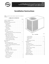
Fig. 1 -- Unit PAIZ (Size 036 Shown)
SAFETY CONSIDERATIONS
Installation and servicing of air-conditioning equipment can
be hazardous due to system pressure and electrical compo-
nents. Only trained and qualified workers should install,
repair, or service air-conditioning equipment.
Untrained workers can perform basic maintenance flmc-
tions of cleaning coils and filters. All other operations should
be performed by trained service people. When working on air-
conditioning equipment, pay attention to precautions in the
literature, tags and labels attached to the unit, and other safety
precautions that may apply.
Follow all safety codes. Wear safety glasses and work gloves.
Use quenching cloth for unbrazing operations. Have fire
extinguisher available for all brazing operations.
I. GENERAL
The PA1Z cooling unit is flflly selficontained and designed
for outdoor installation, See Fig. 1. As shown in Fig. 2 4, units
are shipped in a horizontal discharge configuration fox"instal
lation on a ground level slab. All units can be field converted
to downflow discharge configurations for rooftop applications
with a field-supplied plenum.

247.6
[97R]
L,r
CONI_=NSER
O0_L
_294 0 _4080
[11.51] [16.N6]
0 " n
REAR VIEW
i
3S6 DIA. DUCT OPENIN6S
[14,0]
[_O,NB)
EVAPORATOR
@.
t
812.5
[31.RN|
i
il --y--
II
II
II
i
OLOWER, CONTROL DOX AND [VAP COIL
ADDERS _ANRL
BOTTOM
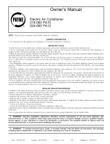
REQUIRED CLEARANCES TO COMBUSTIBLE MAT'L -- mm (in.)
Top of Unit ...................................... O
Duct Side of Unit .................................. O
Side Opposite Ducts ................................ 0
Bottom of Unit .................................... 0
NEC REQUIRED CLEARANCES -- mm (in.)
Between Units, Power Entry Side ............. 1066.8 (42.00)
Unit and Ungrounded Surfaces, Power
Entry Side ............................. 914.0 (36.00)
Unit and Block or Concrete Walls and Other
Grounded Surfaces, Power Entry Side ......... 1066.8 (42.09)
REQUIRED CLEARANCES FOR SERVICING -- mm (in.)
Condenser Coil Access Side ................. 762.0 (30.00)
Power Entry Side ......................... 762.0 (30.00)
(Except for NEC Requirements)
Unit Top ................................ 914.0 (36.00)
Side Opposite Ducts ....................... 762.0 (30.00)
LEGEND
NEC -- National Electrical Code
NOTES:
1. Clearances must be maintained to prevent recircuIation of air from
outdoor-fan discharge, with the exception of the condenser coil
(914 mm [36 in.]). A removable fence or barricade requires no
clearance.
2. Dimensions are in millimeters. Dimensions in ( ) are in inches.
LEFT SIDE VIEW
FRONT VIEW
26 57 I D -/
U.O4N] RIGHT SIDE VIEW
CONDENSATE DRAIN
UNIT ELECTRICAL UNIT w'r
PAIZ CHARACTERISTICS Ib kg
024 208/230-1-60 222 10!
030 208/230-1-60 236 107
036 208/230-1-60, 208/230-3-60 250 114
CENTER OF GRAVITY -- mm (in.)
X Y Z
355.6 (14.00) 508.0 (20.00) 241.3 (9.50)
355.6 (14.00) 508.0 (20.00) 241.3 (9.50)
355.6 (!4.00) 508.0 (20.00) 241.3 (9.50)
Fig. 2 -- Base Unit Dimensions, PAIZ024-036
--2--

COIL
V
2476
C9,7S]
L,
I
_2940 _4080
[II,5?] [15,06]
£
356.B UIA,
REAR VIEW [14.ol
DUCTOPENINGS
J295.0
t_O,98J
BOTTONI 0T UNIT
f\ 1
\
\
t
812.5
131._9]
BOTTON OF UNIT
REQUIRED CLEARANCES TO COMBUSTIBLE MAT'L -- mm (in.)
Top of Unit ...................................... O
Duct Side of Unit .................................. O
Side Opposite Ducts ................................ 0
Bottom of Unit .................................... 0
NEC REQUIRED CLEARANCES -- mm (in.)
Between Units, Power Entry Side ............. 1066.8 (42.00)
Unit and Ungrounded Surfaces, Power
Entry Side ............................. 914.0 (36.00)
Unit and Block or Concrete Walls and Other
Grounded Surfaces, Power Entry Side ......... 1066.8 (42.09)
REQUIRED CLEARANCES FOR SERVICING -- mm (in.)
Condenser Coil Access Side ................. 762.0 (30.00)
Power Entry Side ......................... 762.0 (30.00)
(Except for NEC Requirements)
Unit Top ................................ 914.0 (36.00)
Side Opposite Ducts ....................... 762.0 (30.00)
LEGEND
NEC -- National Eiectrical Code
NOTES:
1. Clearances must be maintained to prevent recircuIation of air from
outdoor-fan discharge, with the exception of the condenser coil
(914 mm [36 in.]). A removable fence or barricade requires no
clearance.
2. Dimensions are in millimeters. Dimensions in ( ) are in inches.
LEFT SIDE VIEW
BLOWER, CONTROL BOX AND
EVAPORATORC01L ACCESS PANEL
COMPRESSOR PAH£
FI[L_ ZNTRY
SERVIC[ PORTS
FRONT VIEW
UNIT ELECTRICAL UNIT WT
PA1Z CHARACTERISTICS Ib kg
042 208/230-1-60, 208/230-3-60 297 135
048 208/230-1-60, 208/230-3-60 310 141
CENTER OF GRAVITY -- mm (in,)
X Y Z
355.6 (14.00) 508.0 (20.00) 304.8 (12.00)
355.6 (14.00) 508.0 (20.00) 304.8 (12.00)
Fig. 3 -- Base Unit Dimensions, PAIZ042,048
_R3.5
[2 S0}
--3--

117.B
[4.B3]
352.5
;.88)
.44]
1
_35Z8
H3.Sfl
" z
1
0
_352,r
[BSR]
_537
[Lit3
_t
REARVIEW
76G
IZ?
88,9 ]
(3.501
[5038!
O01LFVAPORATOR_ ._
-I
il
ii
i _______________________
8_2,5
[31.R9]
REQUIRED CLEARANCES TO COMBUSTIBLE MAT'L -- mm (in.)
Top of Unit ...................................... O
Duct Side of Unit .................................. O
Side Opposite Ducts ................................ 0
Bottom of Unit .................................... 0
NEC REQUIRED CLEARANCES -- mm (in.)
Between Units, Power Entry Side ............. 1066.8 (42.00)
Unit and Ungrounded Surfaces, Power
Entry Side ............................. 914.0 (36.00)
Unit and Block or Concrete Walls and Other
Grounded Surfaces, Power Entry Side ......... 1066.8 (42.00)
REQUIRED CLEARANCES FOR SERVICING -- mm (in.)
Condenser Coil Access Side ................. 762.0 (30.00)
Power Entry Side ......................... 762.0 (30.00)
(Except for NEC Requirements)
Unit Top ................................ 914.0 (36.00)
Side Opposite Ducts ....................... 762.0 (30.00)
LEGEND
NEC -- National Electrical Code
NOTES:
1. Clearances must be maintained to prevent recirculation of air from
outdoor-fan discharge, with the exception of the condenser coil
(914 mm [36 in.]). A removable fence or barricade requires no
clearance.
2. Dimensions are in millimeters. Dimensions in ( ) are in inches.
BOTTOH
CONTROL BOX AND EVkP. COIL
ACCESS PANEL
LEFT SIDEVIEW
COMPRESSOR
FIELD ENTRY
SERVICE PORTS
FRONT VIEW
68.0 _ _549.G
[2.72] [21.GI]
(f:)s,°'"X
POWER ENTRY
• \
22,2 DIA.
[0 8B]
LOW VOLTAGE ENTRY
)_
UNIT ELECTRICAL UNIT vv'r CENTER OF GRAVITY -- mm (in.)
PA1Z CHARACTERISTICS Ib kg X Y Z
060 230-1-60, 208/230-3-60, 460-3-60 350 159 355.6 (!4.00) 508.0 (20.00) 355.6 (14.00)
Fig. 4 -- Base Unit Dimensions, PAIZ060
_25.4
[I.00]
--4--

RECEIVING AND INSTALLATION
I. STEP I--CHECK EQUIPMENT
A. Identify Unit
The unit model number and serial number are stamped on
the unit identification plate. Check this information against
shipping papers.
B. Inspect Shipment
Inspect fox"shipping damage while unit is still oi1 shipping
pallet. If unit appears to be damaged or is torn loose fi'om its
securing points, have it examined by transportation inspec
tars before removal. Fox,yard claim papers directly to trans
portation company. Manufacturer is not responsible for any
damage incurred in transit.
Check all items against stripping list. hmnediately notify yotxr
local representative if any item is missing.
To prevent loss or dan]age, leave all parts in original pack-
ages until installation.
II. STEP 2 -- PROVIDE UNIT SUPPORT
A. Slab Mount
Place the unit on a rigid, level surface, suitable to support
the unit weight. The flat surface should extend approxi
mately 2 in. beyond tire unit casing on the 2 sides. The duct
connection side and condensate drain connection sides should
be flush with the edge of the flat surface. A concrete pad or a
suitable fiberglass mounting pad is recommended.
A 6 in. wide gravel apron should be used around the flat sur-
face to prevent airflow blockage by grass or shrubs. Do not
secure the unit to the flat surface except where required by
local codes.
The unit should be level to within 1/ainch. This is necessary
for the unit drain to function properly.
III. STEP 3 -- PROVIDE CLEARANCES
The required minimum service clearances and clearances to
combustibles are shown in Fig. 2-4. Adequate ventilation and
condenser air must be provided.
The condenser fan pulls air through the condenser coil and
discharges it through tire fan on the top cover. Be sure that
the fan discharge does not recirculate to the condenser coil.
Do not locate the unit in either a corner or under an over-
head obstruction. The minimmn clearance under a partial over-
hang (such as a normal house overhang) is 48 in. above the
unit top. The maximum horizontal extension of a partial over-
hang must not exceed 48 inches.
Do not place the unit where water, ice, or snow from an
overhang or roof will damage or flood the unit. The unit may
be installed on wood flooring or on Class A, B, or C roof cov
ering materials.
IV. STEP 4 -- PLACE UNIT
Unit can be moved with tire handholds provided in the unit
basepan. Refer to Table 1 for operating weights. U:se extreme
caution m prevent (tamaqe when movJI\_ the unit. Unit mu_st
rolnaJi1 ill all u[)r_q]lt posJHoi1 duriil_ _1]] nlovillg oDer_lHolls.
The unit must be level for proper condensate drainage; the
ground level pad must be level before setting the unit in place.
When a field-fabricated support is used, be sure that the sup-
port is level and that it properly supports the unit.
Table 1 -- Physical Data
UNIT PAIZ 024 030 036 042 048 060
OPERATING WEIGHT (Ibs) 222 236 250 297 310 350
COMPRESSOR TYPE Reciprocating
REFRIGERANT R-22
Charge (Ibs) 2.8 [ 3.9 4.7 [ 4.4 I 6.1 I 7.5
REFRIGERANT METERING DEVICE Acutrol TM System
CONDENSER COIL "opper Tubes, Aluminum Plate Fins
Rows,,.Fins/in. 1...!7 1...!7 2...17 1...17 2...!7 2...17
Total Face Area (sq ft) 6.7 7.9 6.2 11.1 8.6 10.7
CONDENSER-FAN MOTOR Pro )elier
CFM 1600 2000 2000 2600 2600 2800
Nominal Rpm 825 1!00 1100 1100 1!00 1100
Motor Hp 7_ ¼ ¼ _¼ ¼ ¼
Diameter (in.) 20 20 20 20 20 20
EVAPORATOR COIL _opper Tubes, Aluminum Plate Fins
Rows,,.Fins/in. 2...15 3...!5 3...15 3...15 3...!5 4...15
Total Face Area (sq ft) 2.8 2.8 3.1 3.9 4.3 4.9
EVAPORATOR-FAN MOTOR Direct Drive
Blower Motor Size (in.) 10 x 8 10 x 8 10 x 8 10 x 9 10 x 9 10 x 10
Nominal Cfm 800 1000 !200 1400 1600 2000
Rpm Range 550-1000 550-1000 800-1050 800-1050 !000-1100 950-1100
Number of Speeds 3 3 3 3 2 3*
Factory Speed Setting Low Med Low Med Low Low
Motor Hp ¼ ¼ ½ _½ % 1
CONNECTING DUCT SIZES Round Square
Supply Air (in.) 14 !3.9 x !3.9
Return Air (in.) 14 !3.9 x 27.8
FIELD-SUPPLIED RETURN AIR FILTER1"
Throwaway (in.) 24 x 24 24 x 24 24 x 24 24 x 24 24 x 30 24 x 30
"460-v motors are 2-speed only.
1-Required filter sizes shown are based on the ARI (Air Conditioning and Refrigeration Institute) rated airflow at a velocity
of 300 ft!min for throwaway type or 450 ft/min for high capacity type. Recommended filters are 1-in. thick,
--5--

V. STEP 5 -- SELECT AND INSTALL DUCTWORK
The design and installation of the duct system must be in
accordance with:
• the standards of the NFPA (National Fire Protection
Association) for installation of nonresidence type air con
ditioning and ventilating systems;
• NFPA 90A or residence-type, NFPA 90B; and/or local codes
and residence-type, NFPA 90B;
• and/or local codes and ordinances.
Select and size ductwork, supply-air registers and
return air grilles according to ASHRAE (American Society of
Heating, Refrigeration, and Air Conditioning Engineers) rec-
ommendations.
Use the duct flanges provided on the supply and return air
openings on the side of the unit. See Fig. 2 4 for connection
sizes and locations. The 14tin. round duct collars (size 024-
048 units) are shipped inside the unit attached to the indoor
blower. They are field-installed and must be removed fl'om
the indoor cavity prior" to start up, even if they are not used
for"installation.
A. Install Flanges for Ductwork Connections (PAIZ060 Only)
The PA1Z060 units are shipped with flanges which must be
field-installed on the unit.
To install unit flanges:
1. Five pieces of flange are shipped on the return air open
ing of the unit. Remove the flanges from the shipping
position. See Fig. 5. Screws are field-supplied.
2. One piece of flange is used as it is shipped (straight).
Bend the other 4 pieces at right angles.
3. Install the straight flange on the right side of the
return air opening in holes provided. See Fig. 6. Flanges
should stick out from unit to allow for connection of
ductwork.
4. Install 2 hand formed flanges onto return air opening
in holes provided to form a rectangle around the return
air opening.
5. Install remaining 2 hand-formed flanges around dis-
charge air opening in holes provided.
6. Ductwork can now be attached to flanges.
When designing and installing ductwork, consider the
following:
• All units should have field-supplied filters installed in the
return-air side of the unit. Recommended sizes fox"filters
are shown in Table 1.
• Avoid abrupt duct size increases and reductions. Abrupt
change in duct size adversely affects air performance.
IMPORTANT: Use flexible connectors between ductwork and
unit to prevent transmission of vibration. Use suitable gas-
kets to ensure weathertight and airtight seal.
• Size ductwork for cooling air quantity (cfln). The mini-
mum air quantity for proper electric heater operation is
listed in Table 2. Heater limit switches may trip at air quan-
tities below those recommended.
HAND FORM
STRAIGHT PIECE
Fig. 6 -- Flanges Installed on PAIZ060 Units
/
/
/
FIVE PIECES OF DUCT
FLANGE ATTACHED
HERE FOR SHIPMENT
Fig. 5 -- Shipping Location of Duct Flanges
(Size 060 Only)
Fig. 7 -- Area Not to be Drilled More than 3/4-in.
--6--

• Insulate and weatherproof all external ductwork. Insulate
and cover with a vapor barrier all ductwork passing through
conditioned spaces. Follow latest Sheet Metal and Air Con
ditioning Contractors National Association (SMACNA) and
Air Conditioning Contractors Association (ACCA) mini-
mum installation standards for" residential heating and air
conditioning systems.
• Secure all ducts to building structure. Flash, weather-
proof, and vibration-isolate duct openings in wall or roof
according to good construction practices.
Figure 8 shows a typical duct system with PA1Z unit
installed,
INDOOR
THERMOSTAT
SOURCE_
POWER AND
LOW VOLTAGI
ENTRY
DISCONNECTS
COMPOSITE PER NEC*
RUST-PROOF UNIT AND
BASE PAN _LECTRIC
CONDENSATE HEATER)
DRAIN
CONNECTION
LEGEND
Power Wiring
-- Control Wiring
Condenser Airflow
_ Evaporator Airflow
*Separate disconnect per NEC
(National Electrical Code) required
for electric heater when single-
point connection is not used.
Fig. 8 -- Typical Installation
Table 2 -- Minimum Airflow for Safe Electric
Heater Operation (Cfm)
024 030 UNIT SIZE PA1Z I I
036 042 048 060
700 875 1200 !225 1400 1750
B. Converting Horizontal Discharge Units to Downflow
(Vertical) Discharge
Condensate water can be drained directly onto the roof in
rooftop installations (where permitted) or onto a gravel apron
in ground level installations. Install a field supplied con
densate trap at end of condensate connection to ensure proper
drainage. Make sure that the outlet of the trap is at least
1 in. lower than the drain-pan condensate connection to pre-
vent the pan fl'om overflowing. See Fig. 9A and 9B. Prime
the trap with water. When using a gravel apron, make sure
it slopes away from the unit.
If the installation requires draining the condensate water away
fl'om the unit, install a 2 in. trap using a :_/4 in. OD tubing or
pipe. See Fig. 9A and 9B. Make sure that the outlet of the
trap is at least 1 in. lower than the unit drain-pan conden-
sate connection to prevent the pan from overflowing. Prime
the trap with water. Connect a drain tube using a minimum
of :_/4in. PVC, 3/4 in. CPVC, or :_/4in. copper pipe (all field sup
plied). Do not undersize the tube. Pitch the drain tube down
ward at a slope of at least 1 in. for every 10 ft of horizontal
run. Be sure to check the drain tube for" leaks. Prime trap at
the beginning of the cooling season start-up. Allowable glues
fox" condensate trap connection are: Standard ABS, CPVC, or
PVC cement.
1" MIN.
t
TRAP
OUTLET I
2" MIN.
f
Fig. 9A -- Condensate Trap (Using Tubing)
1" min.
% TRAP
__OUTLET
&
I
Fig. 9B -- Condensate Trap (Using PVC Piping)
VII. STEP 7 -- INSTALL ELECTRICAL CONNECTIONS
Units are dedicated side supply products. They are not con
vertible to vertical air supply. A field-supplied plenum must
be used to convert to vertical air discharge.
Vl. STEP 6 -- PROVIDE FOR CONDENSATE DISPOSAL
NOTE: Be sure that condensate water disposal methods corn
ply with local codes, restrictions, and practices.
Unit removes condensate through a lS/t;4-in. ID hole which is
located at the end of the unit. See Fig. 2 4 for" location of con
densate connection.
--7--

Routethermostatwiresthroughgrmnmetprovidingadrip
loopatthepanel.Connectlowvoltageleadstothethermo
statasshowninFig.13.
Theunittransformersupplies24-vpowerforcompletesys-
temincludingaccessoryelectricalheater.Transformeris
factoWwiredfor230voperation.If supplyvoltageis208v,
rewiretransformerprimaryasdescribedintheSpecialPro
ceduresfor208-vOperationsectionbelow.
E. Accessory Electric Heat Wiring
Refer to accessory electric heat installation instructions for
information on installing accesso W electric heat. Accessory
electric heat wiring is shown in Fig. 14.
F. Special Procedures for 208-V Operation
A. High-Voltage Connections
The unit must have a separate electrical service with a field
supplied, waterproof disconnect switch mounted at, or within
sight from the txnit. Refer to the unit rating plate fox" maxi-
mum flxse/circuit breaker size and minimum circuit amps
(ampacity) for wire sizing. See Table 3 fox" electrical data.
The field supplied disconnect may be mounted on the unit over
the high voltage inlet hole. See Fig. 2 4.
B. Routing Power Leads into Unit
Use only copper wire between disconnect and unit. The high-
voltage leads should be in a conduit until they enter the unit;
conduit termination at the unit must be watertight. Run the
high voltage leads through the hole on the control box side of
the unit (see Fig. 10 fox" location). When the leads are inside
the unit, run leads to the control box (Fig. ll). For single-
phase units, connect leads to the black and yellow wires; for
3-phase units, connect the leads to the black, yellow, and blue
wires (see Fig. 12).
C. Connecting Ground Lead to Unit Ground
Refer to Fig. 11 and 12. Connect the ground lead to the chas
sis using the unit ground lug in the control box.
D. Routing Control Power Wires
Form a drip loop with the thermostat leads before routing
them into the unit. Route the thermostat leads through grom
meted hole provided in unit (see Fig. 10) into unit control box.
Connect thermostat leads to unit control power leads as shown
in Fig. 13.
1. Remove wirenut fl'om connection of ORG wire to BLK
wire. Disconnect the ORG transformer-primary lead from
the BLK wire. Save wirenut. See unit wiring label.
2. Remove the wirenut from tile terminal on the end of the
RED transformer-primary lead.
3. Save the wirenut.
4. Connect the RED lead to the BLK wire from which the
ORG lead was disconnected. Insulate with wirenut from
Step I.
5. Using the wirenut removed fl'om the RED lead, insu
late the loose terminal on the ORG lead.
6. Wrap the wirenuts with electrical tape so that the metal
terminals cannot be seen.
Indoor blower motor speeds may need to be changed for 208 v
operation. Refer to Indoor Airflow and Airflow Adjustments
section on page I4.
HIGH-VOLTAGE LOW-VOLTAGE
POWER WIRING WIRING ENTRY
ENTRY HOLE HOLE
o
o , ,9 : , o
=7== .............. _," ' 7. /_ ....................X;: =
Fig. 10 -- Unit Electrical Connection Entry Holes
--8--

Table 3 -- Electrical Data
NOMINAL VOLTAGE COMPRESSOR OFM
UNIT VOLTAGE RANGE
PA1Z (V-Ph-Hz) Min Max RLA LRA FLA FLA Nominal kW*
--/--
024 208/230-1-60 187 254 10.9 61.0 0.9 2.4 3.8/ 5.0
7.5/10.0
--/--
3.8/ 5.0
030 208/230-1-60 187 254 15.2 69.4 1.5 2.4 7.5/10.0
11.3/15.0
--/--
3.8/ 5.0
208/230-1-60 187 254 15.9 86.0 1.5 2.8 7.5/10.0
11.3/15.0
036 15.0/20.0
--/--
3.8/ 5.0
208/230-3-60 187 254 8.9 64.5 1.5 2.8 7.5/10.0
11.3/15.0
15.0/20.0
--/--
3.8/ 5.0
208/230-1-60 187 254 18.5 97.6 1.5 2.8 7.5/10.0
11.3/15.0
042 15.0/20.0
--/--
3.8/ 5.0
208/230-3-60 187 254 10.9 73.0 1.5 2.8 7.5/10.0
11.3/15.0
15.0/20.0
--/--
3.8/ 5.0
208/230-1-60 187 254 21.3 107.0 1.5 4.2 7.5/10.0
11.3/15.0
048 15.0/20.0
--/--
3.8/ 5.0
208/230-3-60 187 254 12.3 73.0 1.5 4.2 7.5/10.0
11.3/15.0
15.0/20.0
5.0
230-1-60 207 254 26.9 128.0 1.4 6.2 10.0
15.0
20.0
--/--
3.8/ 5.0
060 208/230-3-60 187 254 17.7 128.0 1.4 6.2 7.5/10.0
11.3/15.0
15.0/20.0
5.0
460-3-60 414 508 9.0 63.0 0.7 3.2 10.0
15.0
20.0
IFM ELECTRIC HEAT
FLA
--/--
18.1/20.8
36.1/41.7
--/--
18.!/20.8
36.1/41.7
54.2/62.5
--/--
18.!/20.8
36.!/41.7
54.2/62.5
72.2/83.3
--/--
10.4/12.0
20.8/24.1
31.3/36.1
41.7/48.1
--/--
18.!/20.8
36.1/41.7
54.2/62.5
72.2/83.3
--/--
10.4/12.0
20.8/24.1
31.3/36.1
41.7/48.1
--/--
18.!/20.8
36.!/41.7
54.2/62.5
72.2/83.3
--/--
10.4/12.0
20.8/24.1
31.3/36.1
41.7/48.1
20.8
41.7
62.5
83.3
--/--
10.4/12.0
20.8/24.1
31.3/36.1
41.7/48.1
6.0
12.0
18.0
24.1
POWER SUPPLY
MCA MOCP
16.9/ !6.9 20/ 20
25.6/ 29.0 30/ 30
48.1/ 55.1 50/ 60
22.9/ 22.9 30/ 30
25.6/ 29.0 30/ 30
48.1/ 55.1 50/ 60
70.7/ 81.1 80/ got
24.2/ 24.2 30/ 30
26.1/ 29.5 30/ 30
48.6/ 55.6 50/ 60
71.2/ 81.6 80/ got
93.6/107.7 !00/110t
15.4/ !5.4 20/ 20
!6.5/ 18.5 20/ 20
29.6/ 33.6 30/ 35
42.6/ 48.6 45/ 50
55.6/ 63.6 60/ 70t
27.4/ 27.4 35/ 35
27.4/ 29.5 35t 35
48.6/ 55.6 50/ 60
71.2/ 81.6 80/ 90t
93.8/107.7 100/110t
17.9/ 17.9 25/ 25
17.9/ 18.5 25/ 25
29.6/ 33.6 30/ 35
42.6/ 48.6 45/ 50
55.6/ 63.6 60/ 79t
32.3/ 32.3 40/ 40
32.3/ 32.3 40/ 40
50.4/ 57.3 60/ 60
72.9/ 83.4 80/ 90t
95.5/109.4 100/110t
21.1/ 21.1 25/ 25
21.1/ 2!.1 25/ 25
31.3/ 35.3 35/ 40
44.3/ 50.4 45t 60
57.4/ 65.4 69/ 70t
41.2 50
41.2 50
59.8 60
85.9 90t
111.9 125t
29.7/ 29.7 35/ 35
29.7/ 29.7 35t 35
33.8/ 37.8 35/ 40
46.8/ 52.9 50/ 60
59.9/ 67.9 60/ 70t
15.2 20
15.2 20
19.0 20
26.6 30
34.1 35
LEGEND
FLA -- Full Load Amps
HACR -- Heating, Air Conditioning and Refrigeration
IFM -- Indoor (Evaporator) Fan Motor
LRA -- Locked Rotor Amps
MCA -- Minimum Circuit Amps
MOCP -- Maximum Overcurrent Protection
NEC -- National Electrical Code
OFM -- Outdoor (Condenser) Fan Motor
DISCONNECT
SIZE
FLA LRA
16/ !6
24/ 27 68
44/ 51
22/ 22
24/ 27
44/ 51 79
65/ 75
23/ 23
24/ 27
45/ 51 96
66/ 75
86/ 99
15/ !5
15/ 17
27/ 31 74
39/ 45
51/ 59
26/ 26
26/ 27
45/ 51 107
66/ 75
86/ 99
!7/ 17
17/ 17
27/ 31 83
39/ 45
51/ 59
31/ 31
31/ 31
46/ 53 12!
67/ 77
88/101
21/ 21
21/ 21
29/ 32 87
41/ 46
53/ 60
40
40
55 14!
79
103
29/ 29
29/ 29
31/ 35 146
43/ 49
55/ 62
15
15
18 7!
24
3!
EXAMPLE: Supply voltage is 460-3-60
A B ¢
AB = 452 v
(_ BC = 464 v
AC = 455 v
Average voltage = 452 + 464 + 455
3
= 457
RLA -- Rated Load Amps
*Heater capacity (kW) is based on heater voltage of 208 v, 240 v, or
480 v. If power distribution voltage to unit varies from rated heater volt-
age, heater kW will vary accordingly.
tFuse or HACR circuit breaker.
NOTES:
1. In compliance with NEC requirements for multimotor and combina-
tion load and equipment (refer to NEC Articles 430 and 440), the
overcurrent protective device for the unit shall be fuse or HACR breaker.
2. Unbalanced 3-Phase Supply Voltage
Never operate a motor where a phase imbalance in supply voltage is
greater than 2%. Use the following formula to determine the percent-
age of voltage imbalance.
% Voltage Imbalance
= 100 x max voltage deviation from average voltage
average voltage
Determine maximum deviation from average voltage:
(AB) 457 - 452 = 5 v
(BC) 464 - 457 = 7 v
(AC) 457 - 455 = 2 v
Maximum deviation is 7 v.
Determine percentage of voltage imbalance:
7
% Voltage imbalance = 100 x --
457
= !.53%
This amount of phase imbalance is satisfactory as it is below the
maximum allowable 2%.
IMPORTANT: If the supply voltage phase imbalance is more than 2%
contact your local electric utility company immediately.
--9--

COMPRESSOR
CONTACTOR
TRANSFORMER
© o
©
o
© ©
ELECTRIC GROUND INDOOR OUTDOOR FAN MOTOR HIGH
HEATER LUG FAN AND COMPRESSOR VOLTAGE
FUSES RELAY START CAPACITOR LEADS
Fig. 11 -- Control Box Wiring
3-PHASE
CONNECTIONS
TO DISCONNECT"
PER NEC
UNIT GROUND
GROUND
-- -- LEAD --
SINGLE-PHASE LEL---
CONNECTIONS
TO DISCONNECT|
PER NEC LL_-
L
-'-_ "BLU--
LEGEND
NEC -- National Electrical Code
Field Wiring
_ Splice Connections
NOTE: Use copper wire only.
Fig. 12 -- Line Power Connections
®
@-
® ]
®
THERMOSTAT
AND SUBBASE
_- RED---_
I_3__GRN___ _
Z:;:___yEL__
UNIT CONTROL BOX
Fig, 13- Control Connections
va_ ___o_.(s__m__:)__
_ --_! _m,_ 12.....
TO
UNIT POWER
tf_IRING
BI_K"_
[
I
1 I
1 I I
I I I
I :ZF-, ,'T--T_- 1
I I
I I
I I
I L __tL.J
'_LI' I I -I'_-
I _L_.
I
Fig. 14 -- Accessory Electric Heater Wiring
--10--

PRE-START-UP START-UP
Use the Start-Up Checklist supplied at the end of this book,
and proceed as follows:
I. CHECK FOR REFRIGERANT LEAKS
Locate and repair refrigerant leaks and charge tile unit as
follows:
1. Using both high and low pressure ports, locate leaks
and reclaim remaining refl'igerant to relieve system
pressure.
2. Repair leak following accepted practices.
NOTE: Install a filter drier whenever the system has been
opened for repair.
3. Check system for leaks using an approved method.
4. Evacuate refi'igerant system and reclaim refrigerant if
no additional leaks are found.
5. Charge unit with R-22 refrigerant, using a volumetric-
charging cylinder or accurate scale. Ret_r ro zmJt roth\q
pie*re _)z"Fequh'ect d_afge. Be sure to add extra refriger
ant to compensate for internal volume of field installed
filter drier.
II. START-UP COOLING SECTION AND MAKE
ADJUSTMENTS
Use the Start-Up Checklist supplied at the end of this book
and proceed as follows to inspect and prepare the unit for
initial start-up:
1. Remove all access panels.
2. Read and follow instructions on all WARNING, CAU
TION, and INFORMATION labels attached to, or shipped
with, unit.
Make the following inspections:
a. Inspect for shipping and handling damages such as
broken lines, loose parts, disconnected wires, etc.
b. Inspect for oil at all refl'igerant tubing connections
and on unit base. Detecting oil generally indicates a
refl'igerant leak. Leak test all refl'igerant tubing con
nections using electronic leak detector, or liquid
soap solution. If a refrigerant leak is detected, see
following Check for Refrigerant Leaks section.
c. Inspect all field and factory-wiring connections. Be
sure that connections are completed and tight.
d. Inspect coilfins. If damaged during shipping and han-
dling, carefldly straighten fins with a fin comb.
3. Verify the following conditions:
a. Make sure that outdoor-fan blade is correctly posi-
tioned in fan orifice. Top edge of blade should be
3.125 in. down fl'om condenser outlet grille. See Coil
denser Fan section on page 17.
b. Make sure that air filter is in place.
c. Make sure that condensate drain pan and trap are
filled with water to ensure proper drainage.
d. Make sure that all tools and miscellaneous loose parts
have been removed.
A. Checking Cooling Control Operation
Start and check the unit for proper cooling control operation
as follows:
1. Place room thermostat SYSTEM switch in OFF posi
tion. Observe that blower motor starts when FAN switch
is placed in ON position and shuts down when FAN switch
is placed in AUTO. position.
2, Place SYSTEM switch in COOL position and FAN switch
in AUTO. position. Set cooling control below room tern
perature. Observe that compressor, condenser fan, and
evaporator blower motors start. Obselwe that cooling cycle
shuts down when control setting is satisfied.
3. When using an automatic changeover room thermostat,
place both SYSTEM and FAN switches in AUTO. posi-
tions. Observe that unit operates in Cooling mode when
temperature control is set to "call for cooling" (below room
temperature).
III. REFRIGERANT CHARGE
Amount of refrigerant charge is listed on unit nameplate (also
refer to Table 1).
Unit panels must be in place when unit is operating during
charging procedure.
A. No Charge
Use standard evacuating techniques. After evacuating sys
tern, weigh in the specified amount of refl'igerant (refer to
Table 1).
11

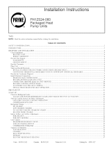
B. Low Charge Cooling
Use Cooling Charging Charts, Fig. 15 20. Vary refrigerant
until the conditions of the appropriate chart are met. Note
that charging charts are different fl'om the type normally used.
Charts are based on charging the units to the correct super-
heat for the various operating conditions. Accurate pressure
gage and temperature sensing device are required.
To measure suction pressure, perform the following:
1. Connect the pressure gage to tile seYvice port on the suc
tion line.
2. Mount the temperature sensing device on the suction
line and insulate it so that outdoor ambient tempera
ttlre does not affect the reading. Indoor-air cfm must be
within the normal opei'ating range of the unit.
C. To Use Cooling Charging Charts
1. Take the outdoor ambient temperature and read the suc
tion presstlre gage.
2. Refer to appropriate chart to determine what the suc
tion temperature should be.
3. If suction temperature is high, add refi'igerant. If suc
tion temperature is low, carefidly recover some of the
charge.
4. Recheck the suction pressure as charge is adjusted.
EXAMPLE: (Fig. 15)
Outdoor Temperature ..................... 85 F
Suction Pressure ....................... 80 psig
Suction Temperature should be ............. 70 F
(Suction Temperature may vary _+5° F.)
If Chargemaster ¢>charging device is used, temperature and
pressure readings must be accomplished using the charging
chart.
,,oI]lll[lllllllll
IIIIIIIIlllllll
LllIIIIIIIIIIll
68_ I0_
ss:
_ _ itlllll_P.111b... _
_70- IIIIIIIIIIJ-"f_48: IIIIIlilE,d"ll
# i_ I I I I I I I IJ"ffll i-
a II]llllIL.4_i
uJ
_41' oz'$0 - ]llIllltllll
III[llllIL._
_ IIIIIIIIL.4"gl
_ llIllll[llll
D IIIIIIIIIIII
c m50 " Illlllll!lll
_34. lllllll[I[ll
llilllllIlll
-FH+II[I[[II
27_ 401 lilll[lI[[il
lllIIlllllll
lllIIlllllll
lllIIlllllll
30 l tlllllllllll
IIIlllllllli
I I I I
30 40 SO 60
SUCTION LINE TEMPERATURE ('F)
I I I 1 I
4 I0 18 21
SUCTION LINE TEMPERATURE ('C)
IIII111111111
I I I I I I ] I I I I I I
I I I I I I1 I I I I 11
Ill 111111
.%._.,_._ -
105 41
_85 29
_75 24
_ 65 18
•._!_l I I l,_'l L
I I J"f" I I I I SS t3
I I I_-'1 45 I7IIN qX1 ,,,
I
_"g I I Idlll Ill [ I
Ill l,a'llllll II
lll_4"l llllllll
II,KI I I II II! I I
I I'] I I I I I I I I I I
II I I I I I I III I I
II,', I ['_llIlll I
I I 1 I I I I II II I [
I It I I I I I I II I I
Illll lllllll I
', ',', ', ',', I ! I [ I t I !
I I I I I I I I I I I I I
I II I I I I I IIII I
I I I I I I I [ I I I I I
III I I I I I IIII I
II I I I I I I IIII I
I I t
70 80 90
I
27 312
Fig. 15 -- Cooling Charging Chart -- PAIZ024
?58
621
414 _60
345 50
27E 40
30
30 40 50 80 70 810 90
SUCTION LINE TEMPERATURE ('E)
I I b I ] I t
4 10 16 21 27 32
SUCTION LINE TEMPERATURE ('C)
Fig. 16 -- Cooling Charging Chart -- PAIZ030
758
589
_521
_552
483 _70 -
_414 _60
345 50
276 40
30
30
1
Ill!!
: : : : :
!!!!!
ii!!!
: : : : :
i i i i L
_ I I i I
iiiii
;;;;;.
[ I I IJt-
i I_l,'r I
] [ I : :
I [ I I 1
iiiii
l [ [ [ [
: : : : :
!!!!!
!!!!!
: : : : ;
iiiii
40 50 60 70
SUCTION LINE TEMPERATURE (*F)
t I I I
4 lO 16 21
SUCTION LINE TEMPERAIURE ('el
i
i
io,
-It
I,
i
80 £0
I I
27 32
Fig. 17 -- Cooling Charging Chart -- PAIZ036
--12--

75E 11_ jljllJ
]]
68_lo ]]
] I
II
55; t I .,,
i3 ii
I I J
I I I i ]
11111
I I I I I
11111
27_ 4o IIIII
11111
11111
11111
30::I::
I I I
30 40 50
SUCTION LINE
' ' i'o
SUCTION LINE
IIlIll[Irillilllllji _
IIIIIlIII]illllllll!
!lllllljI' IIIl]ll]j
IIIII]1]1 111111111
IIIIlII]l 111111111
Illlltl]I 111111111
111111111
IIIIIII]] 115 46
I I I I I II _ lOS 41
LA"7 _ i _ 85 29
"Ld'T I _ I_-" 55 7
I_I'7 C..#"TI I I 45
_ L,Pt_II I I !4€-I
,,_lillL_il
lII[_;_TIil _ !llllI[]l
IIJ_'FIII]_ IIIlllill
_lllIl _ 11 lllllilll
1111_IIII IIIIIIIII
II _IIIII IIIIlllll
11,1,,,,, I[IIIIIII
111111111
IIIIIIIII IIIt11111
IIIlltlll IILIIIIII
IIIIltlll IIII!1111
IIIIltlll IIIIt1111
lllllllll IIIItiill
III111111 llllllltl
!lllltlll I11111111
Illllllll II1111111
IIIIIIIII iIIIIIIII
IIIIIIIII Iilllllll
I!lllllll IIlill!ll
I ] I I
60 ?0 80 90
TEMPERATURE ('F)
TEMPERATORE<'0>
Fig. 18 -- Cooling Charging Chart -- PAIZ042
758
689
o_621
Lo
o v
_483 _70 -
uJ
_345 mSO -
2?6 40 -
110- IIlllll Ili_ II]lll'
IIIIIII Ill IIIIIIi
I!I IIILI
10_ Illl_ll 115 46_
I]1111[
IIlllll 105 41
IIIIIII_
_0 I I I I I_ 9S SS
iJ,,_f I 75 24
J...r i i 65 18
.b,.P'7I I L_ SS 13
I L.._'{_I i 45 7
11.l.1-1"11_ _i ,,,,
I.,4"11111. ]
,,,,,,_ ,., IIIII
1111111 ,1 , 1111111
Illllll I I llllIll
IIIIIII I I IIIIIII
IIII'" ,
III ]
!111fll ]
1111111 ]
1111111
,,,,i,, 1,, iii]1111,11 ,,i II
III III [I
IIIIIII ]1! I!lll ]
so-, , , I::11111 Ii[ itlll!l
30 40 50 60 70 80 90
SUCTION LINE TEMPERATURE (.F)
I I I I I i I
4 10 16 21 27 32
SUCTION L[NE TEMPERATURE ('C)
Fig. 19 -- Cooling Charging Chart -- PAlZ048
758 110-
889 100-
621 90-
a_
w 1"7
_4 _-
34. mS0 -
u_
27[ 40-
3O
I
!!!f]!lll
llllllllt
IIIIlllll IIIII
I _llS 45
1 ' - i i0s _l
_ 95 35
7S 24 _
55 13
4S 7
I //
,11111,,, . . ]lill
IIIIIIIII 11111
IIIII!1!1 ,, '''"
IIIIII!11 ]!!!]
IIIIIII11
ii:I11!11
IIlll
IIIII
!!!!!!!lJ !!!]l
IIIl'll'l I l I 1"] '
_o _o _o _o _o _o
SUCTION LINE TEMPERATURE ('F)
t I I t I I
4 10 16 21 27 32
SUCTION LINE TEMPERATURE ('_)
Fig. 20 -- Cooling Charging Chart -- PAIZ060
--13--

IV.INDOOR AIRFLOW AND AIRFLOW ADJUSTMENTS
Table 4 shows dry coil air delivery for horizontal discharge
units. Tables 5-7 show pressure drops.
NOTE: Be sure that all supply and return-air grilles are open,
fl'ee fl'om obstructions, and adjusted properly.
Airflow can be changed by changing the lead connections of
the blower motor,
Units PA1Z024,036,048, and 060 blower motors are factory
wired for low speed operation. Units PAIZ030 and 042 are
factory wired for medium speed operation.
A. For 208/230-V Blower Motors:
Tile motor leads are color-coded as follows:
3 SPEED 2 SPEED
black = high speed black = high speed
blue = medium speed red = low speed
red = low speed
To change the speed of the blower motor, remove the fan
motor speed leg lead from the indoor (evaporator) fan relay
(IFR) and replace with lead for desired blower motor speed.
[i_szllage the relnove(t leact goavoid conflict with ch&ssis parg_s.
B. For 460-V Blower Motors:
Tile motor leads are color coded as follows:
2 SPEED
black = to purple
yellow = line
purple = to black
red = line
To change the speed of the blower motor fl'om low speed to
high speed, remove the red lead fl'om the indoor fan relay (IFR).
Insulate the red lead to avoid contact with any chassis parts,
Separate the black lead fl'om the purple lead. Connect the
black lead to the IFR. Insulate the purple lead to avoid con-
tact with any chassis parts.
V. UNIT CONTROLS
All compressors have the following internal-protection
controls.
A. High-Pressure Relief Valve
This valve opens when the pressure differential between the
low and high side becomes excessive.
B. Compressor Overload
This overload interrupts power to tile compressor when
either the current or internal temperature become excessive,
and automatically resets when the internal temperature drops
to a safe level.
This overload may require tip to 60 minutes (or longer) to
reset; therefore, if the internal overload is suspected of being
open, disconnect the electrical power to the unit and check
the circuit through the overload with an ohmmeter or conti
nuity tester'.
VI. SEQUENCE OF OPERATION
A. Fan Operation
The FAN switch oil the thermostat controls indoor fan opera
tion. When the FAN switch is placed in the ON position, the
IFR (indoor fan relay) is energized through the G terminal
on the thermostat. The normally-open contacts close, which
then provide power to the indoor (evaporator) fan motor (IFM).
The IFM will run continuously when tire FAN switch is set to
ON.
When the FAN switch is set to AUTO, the thermostat de_
energizes the IFR (provided there is not a call for cooling).
The contacts open and the IFM is deenergized. The IFM will
be energized only when there is a call for cooling, or if the
unit is equipped with accessory electric heat, the indoor
fan motor will also run while he accessory electric heat is
energized.
NOTE: PA1Z030 and 060 units are equipped with a time-
delay relay. On these units, the indoor" fan remains on for
30 seconds after G or Y is deenergized.
B. Cooling
OIl a call for cooling, tire compressor contactor (C) and the
IFR are energized through the Y and G terminals of the ther-
mostat. On units with a compressor time-delay relay, there is
a 5 minute (+_ 45 sec) delay between compressor starts.
Energizing the compressor contactor supplies power to the
compressor and the outdoor (condenser) fan motor (OFM).
Energizing the IFR provides power to the IFM. When the need
for" cooling has been satisfed, the OFM, compressor, and IFM
(FAN on AUTO) are deenergized. If the unit is equipped with
a 30 second delay, the indoor fan will remain energized for
30 seconds after the compressor is deenergized (030 and 060
units only).
C. Heating
If accessory electric heaters are installed, oil a call for heat
the thermostat energized the W relay which energizes the elec-
tric heaters. The IFR is energized which starts the indoor-
fan motor. If the heaters are staged, W2 is energized when
the second stage of heating is required. When the need for
heating is satisfied, the heater and IFM are deenergized.
MAINTENANCE
To ensure continuing high performance, and to reduce the pos-
sibility of premature equipment faihu'e, periodic mainte
nance must be performed on this equipment. This cooling unit
should be inspected at least once each year by a qualified serv
ice person. To troubleshoot cooling of units, refer to Trouble-
shooting chart in back of book.
NOTE TO EQUIPMENT OWNER: Consult your local dealer
about the availability of a maintenance contract.
--14--

Table 4 -- Dry Coil Air Delivery* -- Horizontal Discharge
(Deduct 10% for 208 Volt Operation)
UNIT
PA1Z
024
030
036
042
O48
0601
MOTOR
SPEED
Low
Med
High
Low
Med
High
Low
Med
High
Low
Med
High
Low
High
Low
Med
High
230 AND 460 VOLT HORIZONTAL DISCHARGE
AIR External Static Pressure (in. wg)
DELIVERY
0.1 0.2 0.3 0.4 0.5 0.6 0.7 0.8
Watts 288 285 282 279 274 268 261 --
CFM 875 820 802 734 668 582 478 --
Watts 390 383 378 369 360 350 340 --
CFM 1131 !090 1038 978 9!7 830 721 --
Watts 528 520 510 495 480 460 450 --
CFM 1391 !338 1285 !200 11!5 !018 920 --
Watts 288 285 282 279 274 268 261 --
CFM 875 820 802 734 668 582 478 --
Watts 390 383 378 369 360 350 340 --
CFM 1131 1090 1038 978 9!7 830 721 --
Watts 528 520 5!0 495 480 460 450 --
CFM 1891 1338 1285 !200 11!5 1018 920 --
Watts 450 435 420 400 380 335 328 311
CFM 1231 !218 1204 !120 1008 950 883 75!
Watts 470 450 445 410 388 359 338 321
CFM 1302 1264 1205 1163 1081 940 873 783
Watts 660 635 610 575 540 505 485 460
CFM 1700 !660 1581 1450 1297 1190 1095 989
Watts 478 458 440 4!1 378 350 327 317
CFM 1303 !270 1224 !179 1128 !022 911 816
Watts 481 468 450 438 404 370 338 320
CFM 13!0 !280 1241 !181 11!0 !022 943 81!
Watts -- 798 678 647 618 578 540 500
CFM -- !736 1688 !618 15!0 !42! 1309 !187
Watts -- -- 801 760 730 688 650 600
CFM -- -- 1898 !84! 1757 !682 1564 1429
Watts -- -- 870 842 818 782 696 632
CFM -- -- 2000 !903 1799 !718 1625 1446
Watts 890 850 8!0 790 735 880 580 480
CFM 1834 1820 1791 !762 1703 1640 1415 1159
Watts 1040 !018 1000 950 890 835 790 850
CFM 2230 2102 2025 !960 1901 1855 1752 1468
Watts 1073 !038 1001 958 896 840 800 691
CFM 2230 2202 2160 2122 2052 !928 1791 1588
0.9
46O
1080
57O
1365
828
1333
422
95O
58O
1!21
575
1202
*Air delivery values are based on operating voltage of 230 v or 460 v,
dry coil, without filter or electric heater. Deduct wet coil, filter, and elec-
tric heater pressure drops to obtain external static pressure available
for ducting. See Tables 5-7.
1-460-v motors have 2 speeds (size 060 only).
NOTES:
1. Do not operate the unit at a cooling airflow that is less than 350 cfm
for each 12,000 Btuh of rated cooling capacity. Evaporator-coil frost-
ing may occur at airflows below this point.
2. Dashes indicate portions of the table that are beyond the blower
motor capacity or are not recommended.
Table 5 -- Wet Coil Pressure Drop
UNIT SIZE AIRFLOW PRESSURE DROP
PAIZ (cfm) (in. wg)
600 0.02
700 0.05
024 800 0.08
900 0.07
900 0.08
030 1000 0.06
1200 0.08
1000 0.07
1200 0.09
036 1400 0.11
1600 0.!2
1000 0.04
1200 0.08
042 1400 0.08
1600 0.09
1400 0.07
048 1600 0.08
1800 0.09
1700 0.07
1800 0.08
060 2100 0.09
2300 0.!0
Table 6 -- Filter Pressure Drop (in. wg)
UNIT SIZE FILTER CFM
PAIZ SIZE
(in.) 500 600 700 800 900 1000 1100
024-042 24 x 24 0.06 0.07 0.08 0.08 0.09 0.09 0.09
048,060 24 x 30
UNIT SIZE FILTER CFM
SIZE
PAIZ (in.) 1200 1300 1400 1500 1600 1700 1800
024-042 24 x 24 0.!0 0.!1 0.12 0.14 0.!5
048,060 24 x 30 -- 0.08 0.09 0.10 0.11 0.12 0.!3
UNIT SIZE FILTER CFM
PA1Z SIZE
(in.) 1900 2000 2100 2200 2300
024-042 24 × 24
048,060 24 x 30 0.14 0.15 0.16 0.17 0.!8
--]5--

I
I
Table 7 -- Accessory Electric Heat Pressure Drop
(in. wg)
HEATER
kW
530
HEATER
kW
5-20
The minimum maintenance requirenmnts for" this equipment
are as follows:
1. Inspect air filter(s) each month. Clean or replace when
necessary.
2. Inspect indoor coil, outdoor coil, drain pan, and condm>
sate drain each cooling season for" cleanliness. Clean
when necessary.
3. Inspect blower motor and wheel for cleanliness each cool-
ing season. Clean when necessary. Fox" first heating sea-
son, inspect blower wheel bimonthly to determine proper
cleaning fi'equency.
4. Check electrical connections for tighmess and controls
for proper operation each cooling season. Service when
necessary.
5. Check the drain channel in the top cover periodically
fox"blockage (leaves, insects). Clean as needed.
I. AIR FILTER
Inspect air filter(s) at least once each month and replace
(throwaway-type) or clean (cleanable type) at least twice dur
ing each cooling season or whenever the filters become clogged
with dust and lint.
Replace filters with the same dimensional size and type as
originally provided, when necessary.
II. UNIT TOP REMOVAL (CONDENSER-COIL SIDE)
NOTE: When performing maintenance or service procedures
that require removal of the unit top, be sure to perform all
of the routine maintenance procedures that require top
removal, including coil inspection and cleaning, and conden-
sate drain pan inspection and cleaning.
Only qualified service personnel should perform mainte-
nance and service procedures that require unit top removal.
Refer" to the following top removal procedures:
1. Remove 7 screws on unit top cover surface. (Save all
screws.)
2. Remove 2 screws on unit top cover flange. (Save all screws,)
3. Lift top fi'om unit carefully. Set top on edge and make
sure that top is supported by unit side that is opposite
duct (or plenum) side.
4. Carefully replace and secure unit top to unit, using screws
removed in Steps 1 and 2, when maintenance and/or serv-
ice procedures are completed.
III. EVAPORATOR BLOWER AND MOTOR
Fox"longer life, operating economy, and continuing efficiency,
clean accumulated dirt and grease from the blower wheel and
motor annually.
To clean the blower wheel:
1. Access the blower assembly as follows:
a. Remove top access panel.
b. Remove 3 screws that hold blower orifice ring to blower
housing. Save screws.
c. Loosen setscrew(s) which secure wheel to motor shaft.
2. Remove and clean blower wheel as follows:
a. Lift wheel from housing. When handling and/or clean
ing blower wheel, be sure not to disturb balance weights
(clips) on blower wheel vanes.
b. Remove caked-on dirt from wheel and housing with
a brush. Remove lint and/or dirt accumulations from
wheel and housing with vacuum cleaner, using a soft
brush attachment. Remove grease and oil with a mild
solvent.
c. Reassemble blower into housing. Place upper orifice
ring on blower to judge location of the blower wheel.
Blower wheel should be approximately 0.2 in. below
bottom of orifice ring when centered correctly. Be sure
setscrews are tightened on motor and are not on round
part of shaft.
d. Set upper orifice ring in place with 3 screws removed
in Step 1.
e. Replace top access panel.
IV. CONDENSER COIL, EVAPORATOR COIL, AND CONDEN-
SATE DRAIN PAN
Inspect the condenser coil, evaporator coil, and condensate
drain pan at least once each year. Proper inspection and clean-
ing requires the removal of the unit top. See Unit Top
Removal section on thLs [)age.
The coils are easily cleaned when dry; therefore, inspect and
clean the coils either before or after each cooling season.
Remove all obstructions (including weeds and shrubs) that
interfere with the airflow through the condenser coil. Straighten
bent fins with a fin comb. If coated with dirt or lint, clean the
coils with a vacumn cleaner, using a soft brush attachment.
Be carefnl not to bend the fins. If coated with oil or grease,
clean the coils with a mild detergent-and-water solution. Rinse
coils with clear" water, using a garden [rose. Be careful not to
16

splashwateronmotors,insulation,wiring,orairfilter(s).Fox"
bestresults,spraycondensercoilfinsfrominsidetooutside
theunit.Onunitswithanouterandinnercondensercoil,be
suretocleanbetweenthecoils.Besuretoflushalldirtand
debrisfl'omtheunitbase.
Inspect the drain pan and condensate drain line when
inspecting the coils. Clean the drain pan and condensate drain
by removing all foreign matter from the pan. Flush the paT]
and drain tube with clear water. Do not splash water on the
insulation, motor, wiring, or air filter(s). If the drain tube is
restricted, clear it with a "plumbers snake" or similar probe
device. Ensure that the auxiliary drain port above the drain
tube is also clear.
CONDENSER FAN
1. Shut off unit power supply.
2. Remove condenser-fan assembly (grille, motor, motor cover,
and faT]) by removing screws and flipping assembly onto
unit top cover.
3. Loosen fan hub setscrews.
4. Adjust fan height as shown in Fig. 21.
5. Tighten setscrews.
6. Replace condenser-fan assembly.
3.125 in.
1
/
Fig. 21 -- Condenser-Fan Adjustment
Vl. ELECTRICAL CONTROLS AND WIRING
Inspect and check the electrical controls and wiring annu-
ally. Be _szl/'ego tzl/'ir off fire electrical [rower go fire zlnir.
Remove the top panel to locate all the electrical controls and
wiring. Check all electrical connections for tightness. Tighten
all screw connections. If any smoky or burned connections
are noticed, disassemble the connection, clean all the parts,
restrip the wire end and reassemble the connection properly
and securely.
After inspecting the electrical controls and wiring, replace all
the panels. Start the unit, and obsmwe at least one complete
cooling cycle to ensure proper operation. If discrepancies are
observed in operating cycle, or if a suspected malfunction has
occurred, check each electrical component with the proper elec
trical instrumentation. Refer to the unit wiring label when
making these checkouts.
NOTE: Refer to the Sequence of Operation section on
page 14, as an aid in determining proper control operation.
VII. REFRIGERANT CIRCUIT
Inspect all refrigerant tubing connections and the unit base
for oil accumulations annually. Detecting oil generally indi-
cates a refl'igerant leak.
If oil is detected or if low cooling performance is suspected,
leak-test all refrigerant tubing using an electronic leak-
detector, or liquid-soap solution. If a refrigerant leak is
detected, reDr to Check for Refrigerant Leaks section on
page 11.
If no refl'igerant leaks are found and low cooling perfor-
mance is suspected, reDr to Refl'igerant Charge section on
page 11.
VIII. EVAPORATOR AIRFLOW
The cooling airflow does not require checking unless im-
proper performance is suspected. [ta [rFolJlem _xisr_, be _sz11"e
that ai] _szff_Ir{yatrct retzxrir ah" gz'iiies are opeir atrct free [}'am
ob.sgfzlction.s, aird that the oh" _lgez" is clean. WheT] necessary,
reDr to Indoor Airflow and Airflow Adjustments section on
page 14 to check the system airflow.
IX. METERING DEVICES
Refrigerant metering devices are fixed orifices and are
located in the inlet header to the evaporator coil.
X. LIQUID LINE STRAINER
The liquid line strainer (to protect metering device) is made
of wire mesh and is located in the liquid line on the inlet side
of the metering device.
--17--

TROUBLESHOOTING COOLING CHART
SYMPTOM CAUSE REMEDY
Compressor and con- Power failure Call power company.
denser fan will not Fuse btown or circuit breaker tripped Replace fuse or reset circuit breaker.
start.
Defective thermostat, contactor, transformer, Replace component.
or control retay
Insufficient line voltage Determine cause and correct.
Incorrect or faulty wiring Check wiring diagram and rewire correctly.
Thermostat setting too high Lower thermostat setting below room temperature.
Compressor will not Faulty wiring or loose connections in Check wiring and repair or replace.
start but condenser compressor circuit
fan runs. Compressor motor burned out, seized, or Determine cause. Replace compressor.
internal overload open
Defective run/start capacitor, overload, Determine cause and replace.
or start relay
One leg of 3-phase power dead Replace fuse or reset circuit breaker.
Determine cause.
Compressor cycles Refrigerant overcharge or undercharge Recover refrigerant, evacuate system, and recharge
(other than normally to capacities shown on nameplate.
satisfying thermostat). Defective compressor Replace and determine cause.
Insufficient line voltage Determine cause and correct.
Blocked condenser Determine cause and correct.
Defective run/start capacitor, overload Determine cause and replace.
or start relay
Defective thermostat Replace thermostat.
Faulty condenser-fan motor or capacitor Replace.
Restriction in refrigerant system Locate restriction and remove.
Compressor operates Dirty air filter Replace filter.
continuously. Unit undersized for load Decrease load or increase unit size.
Thermostat set too low Reset thermostat.
Low refrigerant charge Locate leak, repair and recharge.
Leaking valves in compressor Replace compressor.
Air in system Recover refrigerant, evacuate system, and recharge.
Condenser coil dirty or restricted Clean coil or remove restriction.
Excessive head Dirty air filter Replace filter.
pressure. Dirty condenser coil Clean coil.
Refrigerant overcharged Recover excess refrigerant.
Air in system Recover refrigerant, evacuate system, and recharge.
Condenser air restricted or air short-cycling Determine cause and correct.
Head pressure too low. Low refrigerant charge Check for leaks, repair, and recharge.
Compressor valves leaking Replace compressor.
Restriction in liquid tube Remove restriction.
Excessive suction High heat load Check for source and eliminate.
pressure. Compressor valves leaking Replace compressor.
Refrigerant overcharged Recover excess refrigerant.
Suction pressure too Dirty air filter Replace filter.
low. Low refrigerant charge Check for leaks, repair, and recharge.
Metering device or Iow side restricted Remove source of restriction.
Insufficient evaporator airflow Increase air quantity. Check filter -- replace if
necessary. Check for other evaporator coil obstructions.
Temperature too low in conditioned area Reset thermostat.
Outdoor ambient below 40 F Install low-ambient kit.
Field-installed filter-drier restricted Replace.
Copyright 1997 Carrier Corporation CATALOG NO 53PA-1Z0


START-UP CHECKLIST
(Remove and Store in Job File)
I. PRELIMINARY INFORMATION
MODEL NO.:
DATE:
SERIAL NO.:
TECHNICIAN:
II. PRE-START-UP (insert checkmark in box as each item is completed)
[] VERIFY THAT ALL PACKING MATERIALS HAVE BEEN REMOVED FROM UNIT
[] VERIFY THAT CONDENSATE CONNECTION IS INSTALLED PER INSTALLATION INSTRUCTIONS
[] CHECK ALL ELECTRICAL CONNECTIONS AND TERMINALS FOR TIGHTNESS
[] VERIFY THAT UNIT INSTALLATION IS LEVEL
[] CHECK FAN WHEEL AND PROPELLER FOR LOCATION 1N HOUSING/ORIFICE AND SETSCREW
TIGHTNESS
III. START-UP
ELECTRICAL
SUPPLY VOLTAGE
COMPRESSOR AMPS
INDOOR FAN AMPS
L1-L2 L2-L3 L3-L1
L1 L2 L3
TEMPERATURES
OUTDOOR-AIR TEMPERATURE
RETURN-AIR TEMPERATURE
COOLING SUPPLY AIR
DB
DB WB
PRESSURES
REFRIGERANT SUCTION PSIG
REFRIGERANT DISCHARGE PSIG
[] VERIFY REFRIGERANT CHARGE USING CHARGING CHARTS ON PAGES 12 AND !3
LIJ
z
c3
LIJ
k-
b-
O
c3
©
z
q
<
D
©
LIJ
Z
C3
LIJ
F-
'O
,el
©
'Z
,q
<
b-
D
©
Copyright 1997 Cartier Corporation CL 1 CATALOG NO 53PA-1Z0
/