Page is loading ...

WAFER-EHL2 SBC
Page I
[MODEL NAME]
User Manual
WAFER-EHL2
Series
MODEL:
3.5" SBC supports Intel® Celeron® J6412 on-board
SoC with 8GB LPDDR4x memory on board default,
dual display with HDMI and iDPM slot, dual 2.5 GbE,
USB 3.2 Gen 2, M.2, SATA 6Gb/s, 6 COM, iAUDIO,
0°C ~60°C and RoHS
Rev. 1.00 - October 27, 2023

WAFER-EHL2 SBC
Page II
[MODEL NAME]
Revision
Date
Version
Changes
October 27, 2023
1.00
Initial release

WAFER-EHL2 SBC
Page III
[MODEL NAME]
Copyright
COPYRIGHT NOTICE
The information in this document is subject to change without prior notice in order to
improve reliability, design and function and does not represent a commitment on the part
of the manufacturer.
In no event will the manufacturer be liable for direct, indirect, special, incidental, or
consequential damages arising out of the use or inability to use the product or
documentation, even if advised of the possibility of such damages.
This document contains proprietary information protected by copyright. All rights are
reserved. No part of this manual may be reproduced by any mechanical, electronic, or other
means in any form without prior written permission of the manufacturer.
TRADEMARKS
All registered trademarks and product names mentioned herein are used for identification
purposes only and may be trademarks and/or registered trademarks of their respective
owners.

WAFER-EHL2 SBC
Page IV
[MODEL NAME]
Manual Conventions
WARNING
Warnings appear where overlooked details may cause damage to the
equipment or result in personal injury. Warnings should be taken
seriously.
CAUTION
Cautionary messages should be heeded to help reduce the chance of
losing data or damaging the product.
NOTE
These messages inform the reader of essential but non-critical
information. These messages should be read carefully as any directions
or instructions contained therein can help avoid making mistakes.

WAFER-EHL2 SBC
Page V
[MODEL NAME]
Table of Contents
REVISION .......................................................................................................................... I
1 INTRODUCTION .......................................................................................................... 1
1.1 INTRODUCTION ........................................................................................................... 2
1.2 FEATURES ................................................................................................................... 3
1.3 CONNECTORS ............................................................................................................. 3
1.4 DIMENSIONS ............................................................................................................... 4
1.5 DATA FLOW ................................................................................................................ 5
1.6 TECHNICAL SPECIFICATIONS ...................................................................................... 6
2 UNPACKING ................................................................................................................. 8
2.1 ANTI-STATIC PRECAUTIONS ........................................................................................ 9
2.2 UNPACKING PRECAUTIONS ......................................................................................... 9
2.3 PACKING LIST .......................................................................................................... 10
3 CONNECTORS ........................................................................................................... 12
3.1 PERIPHERAL INTERFACE CONNECTORS ..................................................................... 13
3.1.1 WAFER-EHL2 Layout ...................................................................................... 13
3.1.2 Peripheral Interface Connectors ..................................................................... 13
3.1.3 External Interface Panel Connectors ............................................................... 15
3.2 INTERNAL PERIPHERAL CONNECTORS ...................................................................... 15
3.2.1 Clear CMOS Button ......................................................................................... 15
3.2.2 AT/ATX Power Mode Setting ........................................................................... 17
3.2.3 DNX Mode Setting Jumper .............................................................................. 18
3.2.4 Flash Descriptor Override Setting Jumper ...................................................... 19
3.2.5 Internal Audio Connector ................................................................................ 20
3.2.6 ATX 12V Power Connector .............................................................................. 21
3.2.7 RTC Battery Connector .................................................................................... 22
3.2.8 Buzzer Connector ............................................................................................. 23
3.2.9 Chassis status connector .................................................................................. 24
3.2.10 Digital Input/Output Connector ..................................................................... 25
3.2.11 Fan Connector................................................................................................ 26

WAFER-EHL2 SBC
Page VI
[MODEL NAME]
3.2.12 Power LED & HDD LED Connector ............................................................ 28
3.2.13 Power Button Connector ................................................................................ 29
3.2.14 Reset Button Connector ................................................................................. 30
3.2.15 RS-232 Serial Port Connector ....................................................................... 31
3.2.16 RS-232/422/485 serial port connectors ......................................................... 32
3.2.17 SATA 6Gb/s Drive Connector ........................................................................ 33
3.2.18 SATA Power Connector .................................................................................. 34
3.2.19 I2C Connector ................................................................................................ 35
3.2.20 SMBus Connector .......................................................................................... 36
3.2.21 Flash SPI ROM Connector ............................................................................ 37
3.2.22 EC Debug Connector ................................................................................ 38
3.2.23 Internal USB 2.0 Connectors ......................................................................... 39
3.2.24 M.2 A-key Slot ................................................................................................ 40
3.2.25 M.2 B-key Slot ................................................................................................ 42
3.2.26 SIM Card Slot ................................................................................................. 44
3.3 EXTERNAL PERIPHERAL INTERFACE CONNECTOR PANEL ......................................... 45
3.3.1 External 2.5GbE RJ-45 Connectors ................................................................ 45
3.3.2 External DP Connector .................................................................................... 46
3.3.3 External HDMI Connectors ............................................................................. 47
3.3.4 External USB 3.2 Gen 2 Connectors ............................................................... 48
4 INSTALLATION ......................................................................................................... 49
4.1 ANTI-STATIC PRECAUTIONS ...................................................................................... 50
4.2 INSTALLATION CONSIDERATIONS .............................................................................. 51
4.3 M.2 MODULE INSTALLATION .................................................................................... 52
4.4 CHASSIS INSTALLATION ............................................................................................ 53
4.4.1 Heat Spreader .................................................................................................. 53
4.4.2 Motherboard Installation ................................................................................. 55
4.5 RISER CARD INSTALLATION ...................................................................................... 56
4.6 INTERNAL PERIPHERAL DEVICE CONNECTIONS ........................................................ 58
4.6.1 AT Power Connection ...................................................................................... 58
4.6.2 7.1 Channel Audio Kit Installation .................................................................. 59
4.6.3 SATA Drive Connection ................................................................................... 60
4.7 SOFTWARE DRIVERS ................................................................................................. 62
4.7.1 Available Drivers ............................................................................................. 62

WAFER-EHL2 SBC
Page VII
[MODEL NAME]
4.7.2 Driver Download ............................................................................................. 62
5 BIOS .............................................................................................................................. 64
5.1 INTRODUCTION ......................................................................................................... 65
5.1.1 Starting Setup ................................................................................................... 65
5.1.2 Using Setup ...................................................................................................... 66
5.1.2.1 Keyboard Navigation ................................................................................ 66
5.1.2.2 Touch Navigation ...................................................................................... 67
5.1.3 Getting Help ..................................................................................................... 68
5.1.4 Unable to Reboot after Configuration Changes .............................................. 68
5.1.5 BIOS Menu Bar ................................................................................................ 68
5.2 MAIN ........................................................................................................................ 69
5.3 ADVANCED ............................................................................................................... 73
5.3.1 CPU Configuration .......................................................................................... 74
5.3.2 Trusted Computing ........................................................................................... 79
5.3.3 F81804 Super IO Configuration ...................................................................... 80
5.3.3.1 Serial Port 1 Configuration ....................................................................... 81
5.3.3.2 Serial Port 2 Configuration ....................................................................... 82
5.3.3.3 Serial Port 3 Configuration ....................................................................... 83
5.3.3.4 Serial Port 4 Configuration ....................................................................... 85
5.3.3.5 Serial Port 5 Configuration ....................................................................... 86
5.3.3.6 Serial Port 6 Configuration Menu ............................................................. 88
5.3.4 ENE KB9068 Monitor ...................................................................................... 90
5.3.4.1 Smart Fan Mode Configuration ................................................................ 91
5.3.5 Serial Port Console Redirection ...................................................................... 92
5.3.5.1 Console Redirection Settings .................................................................... 93
5.3.6 NVMe Configuration ........................................................................................ 96
5.4 CHIPSET ................................................................................................................... 97
5.4.1 System Agent (SA) Configuration .................................................................... 98
5.4.1.1 Memory Configuration ............................................................................. 99
5.4.1.2 Graphics Configuration ........................................................................... 100
5.4.2 PCH-IO Configuration .................................................................................. 103
5.4.2.1 PCI Express Configuration ..................................................................... 106
5.4.2.1.1 PCIe Root Port Setting ....................................................................... 106
5.4.2.1.2 M2_A_KEY Slot .............................................................................. 108

WAFER-EHL2 SBC
Page VIII
[MODEL NAME]
5.4.2.1.3 M2_B_KEY Slot ............................................................................... 110
5.4.2.2 SATA Configuration ................................................................................. 112
5.4.2.3 HD Audio Configuration .......................................................................... 114
5.5 SECURITY ................................................................................................................ 115
5.6 BOOT ....................................................................................................................... 116
5.6.1 Boot Configuration ......................................................................................... 116
5.6.2 Boot Option Priorities ..................................................................................... 117
5.7 SAVE & EXIT ........................................................................................................... 118
A REGULATORY COMPLIANCE ............................................................................ 120
B PRODUCT DISPOSAL ............................................................................................ 122
C BIOS OPTIONS ........................................................................................................ 124
D WATCHDOG TIMER .............................................................................................. 128
E ERROR BEEP CODE ............................................................................................... 131
E.1 PEI BEEP CODES .................................................................................................... 132
E.2 DXE BEEP CODES ................................................................................................. 132
F HAZARDOUS MATERIALS DISCLOSURE ........................................................ 133
F.1 ROHS II DIRECTIVE (2015/863/EU) ...................................................................... 134
F.2 CHINA ROHS .......................................................................................................... 135

WAFER-EHL2 SBC
Page IX
[MODEL NAME]
List of Figures
Figure 1-1: WAFER-EHL2 ............................................................................................................... 2
Figure 1-2: Connectors .................................................................................................................. 3
Figure 1-3: Dimensions (mm) ........................................................................................................ 4
Figure 1-4: Data Flow Diagram ...................................................................................................... 5
Figure 3-1: Connector and Jumper Locations ...........................................................................13
Figure 3-2: Clear CMOS Location ...............................................................................................16
Figure 3-3: AT/ATX Power Mode Switch Locations ..................................................................17
Figure 3-4: DNX Mode Setting Jumper Location .......................................................................18
Figure 3-5: Flash Descriptor Override Setting Jumper Locations ..........................................19
Figure 3-6: Audio Connector Location .......................................................................................20
Figure 3-7: ATX 12V Power Connector Location .......................................................................21
Figure 3-8: Battery Connector Location .....................................................................................23
Figure 3-9: Buzzer Connector Location .....................................................................................24
Figure 3-10 Chassis Open Connector Location ........................................................................25
Figure 3-11: Digital I/O Connector Location ..............................................................................26
Figure 3-12: Fan Connector Location .........................................................................................27
Figure 3-13: Power LED & HDD LED Connector Location .......................................................28
Figure 3-14: Power Button Connector Location .....................................................................29
Figure 3-15: Reset Button Connector Location .........................................................................30
Figure 3-16: RS-232 Serial Port Connector Location ................................................................31
Figure 3-17 RS-232/422/485 Serial Port Connector Location ...................................................32
Figure 3-18: SATA 6Gb/s Drive Connectors Location ..............................................................33
Figure 3-19: SATA Power Connector Location .........................................................................34
Figure 3-20: I²C Connector Location ..........................................................................................35
Figure 3-21: SMBus Connector Location ...................................................................................36
Figure 3-22: Flash SPI ROM Connector Location ...................................................................37
Figure 3-23: EC Debug Connector Location ..............................................................................38
Figure 3-24: Internal USB 2.0 Connectors Locations ...............................................................39
Figure 3-25: M.2 A-key Slot Location ..........................................................................................40
Figure 3-26: M.2 B-key Slot Location ..........................................................................................42
Figure 3-27: SIM Card Slot Location ...........................................................................................44

WAFER-EHL2 SBC
Page X
[MODEL NAME]
Figure 3-28: External Peripheral Interface Connector ..............................................................45
Figure 3-29: LAN LED Location ...................................................................................................46
Figure 3-30: External DP Connector Pinouts .............................................................................47
Figure 3-31: External HDMI Connector Location .......................................................................47
Figure 3-32: External USB 3.2 Gen 2 Connectors Location .....................................................48
Figure 4-1: Inserting The M.2 Module Into The Slot At An Angle ..........................................52
Figure 4-2: Securing The M.2 Module .........................................................................................53
Figure 4-3 Heat Sink Retention Screws ......................................................................................54
Figure 4-4 Passive Cooling ..........................................................................................................54
Figure 4-5 Active Cooling ............................................................................................................54
Figure 4-6: DRPC-W-EHL22-R10 Figure 4-7: DRPC-W-EHL22-R10 with Extra Fan
Cooling ..................................................................................................................................55
Figure 4-8: Motherboard Installation Example ..........................................................................56
Figure 4-9:Outwards Riser Card Installation Example Figure 4-10: NWR-L2S-R10 ............56
Figure 4-11: Inwards Riser Card Installation Example Figure 4-12: NWR-R2S-R10 ...........57
Figure 4-13:L-shaped Bracket Installation Example .................................................................57
Figure 4-14: Power Cable to Motherboard Connection ............................................................58
Figure 4-15: Connect Power Cable to Power Supply ................................................................59
Figure 4-16: 7.1 Channel Audio Kit .............................................................................................60
Figure 4-17: SATA Drive Cable Connection ...............................................................................61
Figure 4-18: IEI Resource Download Center ..............................................................................62
Figure 5-1: BIOS Starting Menu ..................................................................................................65
Figure 5-2: BIOS Options and Configured USB Ports ............................................................105

WAFER-EHL2 SBC
Page XI
[MODEL NAME]
List of Tables
Table 1-1: Technical Specifications ............................................................................................ 7
Table 2-1: Packing List .................................................................................................................10
Table 2-2: Optional Items .............................................................................................................11
Table 3-1: Peripheral Interface Connectors ...............................................................................15
Table 3-2: Rear Panel Connectors ..............................................................................................15
Table 3-3: Clear CMOS Pinouts ...................................................................................................16
Table 3-4: AT/ATX Power Mode Switch Pinouts ........................................................................17
Table 3-5: DNX Mode setting Jumper Pinouts ...........................................................................18
Table 3-6: Flash Descriptor Override Setting Jumper Pinouts ................................................19
Table 3-7:Audio Connector Pinouts ...........................................................................................21
Table 3-8: ATX 12V Power Connector Pinouts ..........................................................................21
Table 3-9: Battery Connector Pinouts ........................................................................................23
Table 3-10: Buzzer Connector Pinouts .......................................................................................24
Table 3-11 Chassis Status Connector Pinouts ..........................................................................25
Table 3-12: Digital I/O Connector Pinouts ..................................................................................26
Table 3-13: Fan Connector Pinouts ............................................................................................27
Table 3-14: Power LED & HDD LED Connector Pinouts ...........................................................28
Table 3-15: Power Button Connector Pinouts ...........................................................................29
Table 3-16: Reset Button Connector Pinout ..............................................................................30
Table 3-17: RS-232 Serial Port Connector Pinouts ...................................................................31
Table 3-18 RS-232/422/485 Serial Port Connector Pinouts ......................................................32
Table 3-19: SATA 6Gb/s Drive Connectors Pinouts ..................................................................33
Table 3-20: SATA Power Connector Pinouts .............................................................................34
Table 3-21: I²C Connector Pinouts .............................................................................................35
Table 3-22: SMBus Connector Pinouts ......................................................................................36
Table 3-23: Flash SPI ROM Connector Pinouts .........................................................................37
Table 3-24:EC Debug Connector Pinouts ..................................................................................38
Table 3-25: Internal USB 2.0 Connectors Pinouts .....................................................................39
Table 3-26: M.2 A-Key Slot Pinouts ............................................................................................41
Table 3-27: M. 2 B-key Slot Pinouts ............................................................................................43
Table 3-28: SIM Card Slot Pinouts ..............................................................................................44

WAFER-EHL2 SBC
Page XII
[MODEL NAME]
Table 3-29: External 2.5GbE RJ-45 Connectors Pinouts ..........................................................45
Table 3-30: LAN LED Pinouts ......................................................................................................46
Table 3-31: External DisplayPort Connector Location .............................................................46
Table 3-32: External HDMI Connector Pinouts ..........................................................................47
Table 3-33: External USB 3.2 Gen 2 Connectors Pinouts ........................................................48
Table 5-1: BIOS Navigation Keys ................................................................................................66
Table 5-2: BIOS On-screen Navigation Keys .............................................................................67

WAFER-EHL2 SBC
Page 1
Chapter
1
1 Introduction

WAFER-EHL2 SBC
Page 2
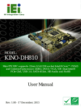
1.1 Introduction
Figure 1-1: WAFER-EHL2
The WAFER-EHL2 is a 3.5" industrial motherboard equipped with an Intel® Celeron®
J6412 quad-core Elkhart Lake processor supporting 4 cores, turbo up-to 2.60 GHz with
1.5M cache, and supports onboard LPDDR4x-3200MHz with 8 GB memory, up to 16GB.
The WAFER-EHL2 includes a HDMI1.4 (up to 4096 x 2160@30Hz) connector, a DP1.4
(up to 4096 x 2160 @60Hz) connector and one IEI iDPM slot for triple independent display.
Expansion and I/O include one M.2 A-key slot for Wi-Fi or Bluetooth expansions, one M.2
B-key slot with SIM holder for 5G module or NVMe storage expansions and one PCIe x4
slot with x2 signal for installing riser card.Two USB 3.2 Gen 2 connectors on the rear panel,
four USB 2.0 connectors by pin header and one SATA 6Gb/s connector. Serial device
connectivity is provided by two internal RS-232/422/485 connectors and four RS-232
connectors. Two RJ-45 2.5GbE connectors provide the system with smooth connections
to an external LAN.

WAFER-EHL2 SBC
Page 3
1.2 Features
Some of the WAFER-EHL2 motherboard features are listed below:
Intel® 10nm Celeron® J6412 On-board SoC, 4 cores and 4 threads, base
frequency 2.00GHz, turbo frequency up to 2.60GHz, 1.5MB cache
Two Intel® I225V 2.5GbE ports
Two USB 3.2 Gen 2, four USB 2.0, two RS-232/422/485 and four RS-232
M.2 A key, M.2 B key and PCIe x4 slot (x2 signal) expansions
Support triple independent display via HDMI, DP and IEI iDPM
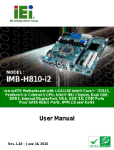
1.3 Connectors
The connectors on the WAFER-EHL2 are shown in the figure below.
Figure 1-2: Connectors

WAFER-EHL2 SBC
Page 4
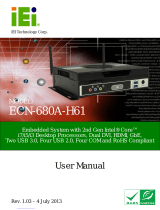
1.4 Dimensions
The dimensions of the board are listed below:
Figure 1-3: Dimensions (mm)

WAFER-EHL2 SBC
Page 5
1.5 Data Flow
Shows the data flow between the system chipset, the CPU and other components installed
on the motherboard.
Figure 1-4: Data Flow Diagram

WAFER-EHL2 SBC
Page 6
1.6 Technical Specifications
WAFER-EHL2 technical specifications are listed below.
Specification
WAFER-EHL2
SoC
Onboard Intel® Atom® x6000 series / Pentium® / Celeron®
processor (Elkhart Lake platform)
Intel® Celeron® J6412 on-board SoC
(up to 2.6GHz, quad-core, 1.5M Cache, TDP=10W)
BIOS
AMI UEFI BIOS
Memory
On-board LPDDR4x 3200 MHz 8GB, up to 16 GB
Graphics
Intel® UHD Graphics
Display Output
Triple independent display
1 x HDMI 1.4a (up to 4096 x 2160 @ 30Hz)
1 x DP 1.4a (up to 4096 x 2160 @ 60Hz)
1 x IEI iDPM 3040 slot (only for IEI eDP/LVDS/VGA module)
Ethernet
LAN1: Intel® I225V 2.5GbE
LAN2: Intel® I225V 2.5GbE
Digital I/O
12-bit digital I/O by 14-pin (2x7) header
Embedded Controller
ENE KB9068
Watchdog Timer
Software programmable support 1~255 sec. system reset
I/O Interface
Audio Connector
1 x iAUDIO supports IEI AC-KIT-888S Audio Kit (2x5 pin)
Serial Ports
2 x RS-232/422/485 by 9-pin (1x9 pin, P=1.25) wafer
4 x RS-232 by 9-pin (1x9 pin, P=1.25) wafer
USB Ports
2 x USB 3.2 Gen 2 on rear I/O
4 x USB 2.0 by 8-pin (2x4 pin, P=2.0) header
Front Panel
1 x Power LED and HDD LED connector by 6-pin (1x6) wafer
1 x Power button connector by 2-pin wafer
1 x Reset button connector by 2-pin wafer
Fan
1 x CPU fan connector by 4-pin (1x4) wafer

WAFER-EHL2 SBC
Page 7
Specification
WAFER-EHL2
I2C
1 x I2C connector by 4-pin (1x4) wafer
Storage
1 x SATA 6Gb/s with 5V SATA power connector
onboard eMMC (optional UP TO 256G)
Expansions
1 x M.2 A Key for WIFI & BT (2230)(PCIe Gen3 x1/USB 2.0
signal)
1 x M.2 3042/2242 B key (PCIe Gen3 x2 & USB 2.0)
1 x On-board SIM card socket (hinge type) for M.2 B key
1 x PCIe Gen3 x4, PCIe Gen3 x2 signal (x2 or x1+x1)
Environmental and Power Specifications
Power Supply
12 V DC input only (AT/ATX support)
Power Connector
1 x Internal power connector by 4-pin (2x2) connector
Power Consumption
[email protected] (Intel® Celeron® J6412 2.0GHz with on-board
8GB 3200MHz LPDDR4 memory and EUP enabled)
Operating Temperature
0°C ~ 60°C
Storage Temperature
-30°C ~ 70°C
Humidity
5% ~ 95%, non-condensing
Physical Specifications
Dimensions
146mm x 102mm
Weight GW/NW
850g / 350g
Table 1-1: Technical Specifications

WAFER-EHL2 SBC
Page 8
Chapter
2
2 Unpacking
/