Page is loading ...

QUICK START GUIDE
Machine Tending
Solution
For installation on e-Series
Universal Robots
X-990115-A

1.WHAT IS SUPPLIED
Standard upon delivery of
SOL-MT-ES-DUAL-HND:
• Single or Dual Gripper assembly:
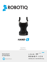
- Hand-E Gripper(s)
- Coupling(s)
- Dual bracket (90° mechanical bracket for Dual Gripper)
- Hand-E Fingertip kits
• Stacklight Monitoring Sensors:
- 3x Photosensors
- 3x 10 m sensor cables
- Cable ties
• Button Activator:
- 2x Mounting brackets
- Double-sided tape
- 4 mm air tube (10 m long)
• Air Nozzle:
- 2x Nozzle sets
- 8 mm air tubing (10 m long)
• Pneumatic Panel:
- Solenoid valves
- Air regulator
- Shutoff valve
- Solenoid valve cables
• Robot to Machine (R2M) Interface:
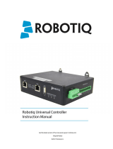
- R2M controller
- Power supply cable
• Machine Tending Copilot Dongle
• Cable management system
• Foot Switch Activator:
- 1x 6 mm air tubing (10 m long)
• Robot Pedestal*
- 4x Concrete anchors
• Robotiq Wrist Camera*
*Optional components
4. GET THE LATEST
3.TOOLS NEEDED
This step-by-step guide will allow you to install
and use your Robotiq Machine Tending (MT)
Solution on e-Series Universal Robots (UR).
Refer to the product’s instruction manual and
eLearning course for advanced instructions.
THANK YOU FOR
CHOOSING ROBOTIQ
Included Not included
• 2 mm hex key
• 2.5 mm hex key
• 3 mm hex key
• 4 mm hex key
• 8 mm torque wrench
• #00 Phillips screwdriver
•
Cutter pliers
• Hammer drill
• Concrete anchor socket
The operator must have read and understood all of the
instructions in the user manual (available at
support.robotiq.com) before operating the Machine Tending
Solution.
The entire cell shall be subjected to a comprehensive risk
assessment process before it can be used.
Do not operate or power on the Machine Tending Solution
before securing the robot and clearing the machine area.
Make sure the air supply is secured. Failure to properly
secure and install the equipment can result in material
damage and bodily injury.
Make sure to follow all enforceable safety rules and regulations
while using the Machine Tending Solution.
2.SAFETY & WARNING
!
Always wear all required personal protective equipment in
accordance with the enforceable safety standards.
Download URCaps
1. Go to support.robotiq.com
2. Select Machine Tending Solution > Universal Robots >
Software > Robotiq URcaps
3. Download the Machine Tending and Hand-E Gripper
URCaps
4. Save the ZIP files on a USB storage device
Download User Manual
1. Go to support.robotiq.com
2. Select CNC Machine Tending Solution > Universal
Robots > Documents > Robotiq CNC Machine Tending
Solution Manual

5. ROBOT POSITIONING
Robot Installation
Follow these steps if you are using the Robotiq Pedestal. For
other robot installations, please refer to specific product
requirements.
1.Run the robot cable through the inner pedestal section and
pull the cable out at the bottom of the pedestal.
The 8 mm air tubing can also run through the pedestal if
needed.
2. Level the pedestal; set it at right angle with the machine.
3. Secure the pedestal to the floor using the anchors provided.
4. Place the robot on the robot base plate.
5. Secure the robot using four (4) M8 x 25 mm screws.
The torque value required is 20 Nm.
6. Refer to the Universal Robots technical literature to operate
the robot.
7. Install the previously downloaded URCaps on the robot.
Position the robot base so as to reach all components of the
machine tending cell (workholding, part presentation, CNC
door handle, etc.)
The machine tending components the robot has to reach
should be at least 300 mm from the center of the robot
base.
The farthest machine tending component the robot has to
reach should be at maximum distance of:
UR3: 500 mm
UR5: 850 mm
UR16: 900 mm
UR10: 1300 mm
Refer to the specifications provided by Universal Robots for
further information on mounting the robot.
6. ROBOT INSTALLATION

1. Identify the final location of the R2M Interface,
then mount it. There are two mounting options:
a. Applying double-sided tape under the
device;
b. Securing the device using the mechanical
hardware provided.
2. Connect the power cable to the R2M Interface
and to a power outlet.
3. Connect one end of the the Ethernet (RJ45) cable
to the R2M Interface and the other end to the
USB/Ethernet cable. connect the USB cable to a
USB port in the robot controller.
4. Configure the IP address to establish
communication between the UR controller and
R2M Interface. Go to Installation - Modbus and
enter the address of the R2M Interface
172.17.101.13
5. Configure the Register inputs and Digital outputs
of the R2M Interface using the Add new signal
button.
Follow the instructions in the Stacklight Detector
and Pneumatic Panel sections.
To change the IP address of the R2M Interface, refer
to this product’s instruction manual
7. GRIPPER MOUNTING
Refer to the Robotiq technical literature for advanced
mounting information, and Wrist Camera installation steps.
1. Move the robot tool flange to make it point upwards.
2. Mount the dual bracket on the tool flange using the
provided 4x M6 screws, dowel pin and 4x toothlock washers.
3. Mount each gripper coupling to a gripper adapter plate
bracket using the provided 4x M6 screws, dowel pin and 4x
toothlock washers.
4. Mount each Gripper to a gripper coupling using 4x M5
screws and 4x toothlock washers.
5. Install the communication splitter on the dual gripper
adapter plate using 2x M4 screws and washers.
6. Connect the M8 splitter to the robot tool connector.
7. Connect the first coupling to the M8 splitter.
8. Change the Gripper ID via the robot’s interface > Installation >
URCaps > Grippers.
9. Disconnect the first Gripper, then connect the second Gripper.
10. Change the second Gripper’s ID.
11. Reconnect the second Gripper.
For details on using the Fingertips Extender Kit, please refer
to the instruction manual of the Machine Tending Solution.
To avoid confusion, identify each gripper appropriately.
8.ROBOT TO MACHINE (R2M)
INTERFACE

1. Install the appropriate mounting bracket on the machine
controller panel using the tape provided.
2. Mount the Button Activator onto the mounting bracket
using 2x M3 screws.
3. Adjust the height of the Button Activator.
4. Install the protective cover.
5. Connect the 4 mm air tubing to the air tube fitting.
6. Verify that the safety clip is properly installed.
7. Connect the 4 mm air tubing to the Button Activator’s
pressure regulator on the pneumatic panel.
Follow these steps to set the pressure:
a. Slowly increase the Button Activator pressure
until the Activator Button is pushed to the
bottom.
b. Check if it can be pushed any further: if it can,
repeat the previous step.
c. Add 1 bar to the Button Activator pressure
regulator, then lock the adjustment knob in
place.
8.Test using the Modbus configuration menu.
9.Secure the air tubing using a cable management system
1. Identify the final location of the Robotiq
Pneumatic Panel, then install it using the
hardware provided.
2. Connect the solenoid valve cables to the R2M
Interface.
3. Configure the communication via Modbus
protocol (see Robot to Machine Interface
section)
4. Configure the Digital Output signals. Use
addresses 1 to 4.
5. Connect the air tubing to the main air supply
system.
6. Open the shut off valve.
7. Set the general system pressure to 80-90 psi.
9.PNEUMATIC PANEL
10.BUTTON ACTIVATOR

1. Secure each stacklight detector using a cable tie
2. Connect the female end of each M8 cable to a stacklight
detector and tighten the screw-on connector.
3. Connect the male end of each M8 cable to the R2M Interface
and tighten the screw-on connector..
4. Adjust the detection threshold using the provided #00 Phillips
screwdriver until the indicator light turns ON.
5. Configure the communication via Modbus protocol (see
Robot to Machine Interface section)
6. Configure the Register Input signals. Use addresses 1 to 3.
The signal should vary between 0 (light OFF), 1 (light ON) and
2 (blink).
1. Install the adjustment plate under the Foot Switch Activator
using the two low head screws and the 4 mm hex key. Do not
fasten yet.
2. Turn the assembly on its side.
3. Adjust the position of the foot switch until it touches the Foot
Switch Activator. Align the foot switch hole with the threaded
hole of the adjustment plate. Using the 4 mm hex key, fasten
the two low head screws already in place.
4. Get the assembly back up and remove the cover of the foot
switch.
5. Choose the socket head screw that corresponds to the
assembly. Insert it in the washer and, using the 4 mm hex key,
fasten the screw in the hole going through the footswitch and
the adjustment plate.
6. If the foot switch does not have an anti-trip safety latch, go to
the next step. If it does, turn the adjustment knob until it
pushes the anti-trip safety latch to the bottom.
7. Test the assembly manually to ensure it is operating properly.
Put the cover back on the foot switch.
8. Connect the 6 mm air tubing to the Foot Switch Activator.
Make sure the safety clip is properly installed.
9. Connect the 6 mm air tubing to the solenoid valve.
10. Test using the URCap or the Modbus configuration menu.
11. Secure the air tubing using a cable management system.
11.STACKLIGHT DETECTOR
12.FOOT SWITCH ACTIVATOR
Turn off and de-energize the machine prior to
mounting the foot switch activator on the machine’s
foot switch.
!

1. Choose the location of the air nozzle.
2. Install the air nozzle assembly and tighten it using two M4
screws and the 3 mm hex key.
3. Connect the 8 mm air tubing to the air nozzle. Ensure the
safety clip is properly installed.
4. Run the 8 mm air tubing along the robot arm.
5. Install the cable management device.
6. Connect the 8 mm air tubing to the solenoid valve.
7. Test with the Test button in the URCap.
elearning.robotiq.com
13.AIR NOZZLE
14.USING THE SOFTWARE
1. Tap the Program button at the top of the screen.
2. Tap the URCaps button in the navigation pane on the left.
3. Select Machine Tending in the dropdown list.
4. Go to the Command tab and select Configuration.
a. Choose the options that correspond to your cell
components.
b. Click the Generate button.
5. In the Command tab, select Smart Move.
6. Teach each key waypoint.
7. Teach the Smart Move Map, preferably with the end
effector holding a blank part.
a. Move the robot to the above_infeed key waypoint.
b. In the Smart Move tab, tap Start Recording.
c. Using the ActiveDrive feature, move the robot to
each key waypoint, close to, but not in direct
contact with the machine tending component,
replicating a complete part loading and unloading
sequence.
d. In the Smart Move tab, tap Stop Recording.
8. Select Macro List in the program tree.
9. Select a Macro.
10. Follow the instructions on the screen.
11. Repeat with the other Macros in the list.
/


