Page is loading ...

Get the latest version of the manual at support.robotiq.com
Original Notice
©2021 Robotiq Inc.

Robotiq Universal ControllerInstruction Manual
Table of Contents
Table of Contents 2
Revisions 3
1. General Presentation 4
2. Safety 6
2.1 Warning 7
2.2 Intended Use 8
3. Installation 9
3.1 Scope of Delivery 9
3.2 Environmental and operating conditions 10
3.3 Mechanical connections 11
3.4 Power supply specifications 12
3.5 Wiring 13
3.5.1 Power connection 15
3.5.2 Communication connection 17
4. Control 26
4.1 Overview 26
4.2 Status LEDs 26
4.2.1 Supply LED 27
4.2.2 Communication LED 27
4.2.3 Fault LED 27
4.3 Controller register mapping 28
4.4 Robot output registers & functionalities 28
4.5 Robot input registers & status 29
5. User Interface 30
6. Specifications 31
6.1 Technical dimensions 31
6.2 Mechanical specifications 32
6.3 Moment of inertia and center of mass 32
6.4 Electrical ratings 33
7. Maintenance 34
8. Spare Parts, Kits and Accessories 35
9. Troubleshooting 36
10. Warranty 38
11. Contact 39
©Robotiq inc. 2008 - 2021 2

Robotiq Universal ControllerInstruction Manual
Revisions
Robotiq may modify this product without notice, when necessary, due to product improvements, modifications or changes in specifications. If such modification is
made, the manual will also be revised, see revision information. See the latest version of this manual online at http://support.robotiq.com/.
Revision 2021/06/07
Section 3.5.1 Power Connections updated
Revision 140626
Manual release
Copyright
© 2008-2021 Robotiq Inc. All rights reserved.
This manual, and the product it describes, are protected by the Copyright Act of Canada, by laws of other countries, and by international treaties, and therefore
may not be reproduced in whole or in part, whether for sale or not, without prior written consent from Robotiq. Under copyright law, copying includes translation
into another language or format.
Information provided by Robotiq in this document is believed to be accurate and reliable. However, no responsibility is assumed by Robotiq for its use. There may
be some differences between the manual and the product if the product has been modified after the edition date.
The information contained in this document is subject to change without notice.
©Robotiq inc. 2008 - 2021 3

Robotiq Universal ControllerInstruction Manual
1. General Presentation
The terms "Controller", "Universal Controller", "Robotiq Controller" , "K-Model", and "Robotiq Universal Controller" used in the following manual all refer to the
Robotiq Universal Controller. The Robotiq Universal Controller is a robotic peripheral controller for other Robotiq devices and communication with other robot
controllers. The Universal Controller is designed for industrial applications with various communication protocols and is common to all Robotiq devices.
Note
The following manual uses the metric system, unless specified, all dimensions are in millimeters.
Note
The following section presents the key features of the Controller and must not be considered as related to Controller operation, each feature is detailed in
an appropriate section of the manual. Safety guidelines must be read and understood before any operation is attempted with the Controller.
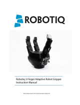
The Universal Controller has two panels as shown in Figure 1.1. The front panel is called the Communication Panel and covers standard and optional
communication features. The side panel is called the Supply Panel and features the connector for supply of the Controller, setup of emergency stop and the
Robotiq Device Connector.
Figure 1.1 : The Robotiq Universal Controller.
©Robotiq inc. 2008 - 2021 4

Robotiq Universal ControllerInstruction Manual
All Robotiq Universal Controllers have a standard USB 2.0 port available for serial communication. Optional communication panel choices are :
lEthernet family protocols
lEthernet / IP
lModbus TCP
lEtherCAT
lPROFINET
lDeviceNet
lCANopen
lProfibus
The Supply Panel is standard on all Controllers and includes a supply connector with an emergency stop feature and the Robotiq Device Connector for connection
to the various Robotiq Grippers.
Info
See section 3.5.1 Power connection for details on the Supply Panel and section 3.5.2 Communication connection for details on the Communication Panel.
The Robotiq User Interface can be used via the standard USB 2.0 port to control or configure Robotiq devices. Visit http://support.robotiq.com to get the latest
installer of the Robotiq User Interface along with appropriate documentation.
See the Robotiq User Interface Instruction Manual for details on usage of the RUI.
©Robotiq inc. 2008 - 2021 5

Robotiq Universal ControllerInstruction Manual
2. Safety
Warning
The operator must have read and understood all of the instructions in the following manual before handling the Robotiq Universal
Controller and the associated Gripper device.
The term "operator" refers to anyone responsible for any of the following operations on the Universal Controller and associated Gripper device :
lInstallation
lControl
lMaintenance
lInspection
lCalibration
lProgramming
lDecommissioning
This documentation explains the various components of the Universal Controller and its general operation. Read this documentation and the associated Robotiq
Gripper device documentation and be sure to understand its contents before handling the Controller or Gripper.
The drawings and photos in this documentation are representative examples and differences may exist between them and the delivered product.
©Robotiq inc. 2008 - 2021 6

Robotiq Universal ControllerInstruction Manual
2.1 Warning
Note
Any use of the Controller in noncompliance of these warnings is inappropriate and may cause injury or damage.
Warning
Concerning Controller use in a robot environment (with robot and/or Robotiq Grippers):
lRespect all robot safety recommendations.
lRespect all Gripper safety recommendations.
lController must be installed in a secured and clean environment.
lMake sure all cord sets are always secured at the Gripper, the Controller and at the robot.
lRespect power supplies according to the associated Robotiq device.
lRespect fusing according to the associated Robotiq device.
lAlways respect the recommended keying for electrical connections.
lNever supply the Gripper with an alternative current source.
Any usage of the Controller beyond these definitions is inappropriate and may cause injury or damage.
Note
Usage of the Universal Controller with an emergency stop is strongly recommended.
©Robotiq inc. 2008 - 2021 7

Robotiq Universal ControllerInstruction Manual
2.2 Intended Use
The Controller unit is designed for control of Robotiq devices such as the Robotiq Adaptive Robot Gripper series.
Caution
The Controller is NOT intended for robot control.
The product is intended to be installed in parallel to a robot or other automated machinery or equipment.
Note
Always comply with local and/or national laws, regulations and directives on automation safety and general machine safety.
The unit may be used only within the range of its technical data. Any other use of the product is deemed improper and unintended use. Robotiq will not be liable for
any damages resulting from improper use.
©Robotiq inc. 2008 - 2021 8

Robotiq Universal ControllerInstruction Manual
3. Installation
Warning
Be sure to read and understand the safety instructions related to the Universal Controller prior to installation.
Warning
Respect robot and Gripper safety measure and installation before operating or even turning on the power supply.
3.1 Scope of Delivery
Standard upon delivery :
lRobotiq Universal Controller (UNI-CTR-001-XXXX)
lReplace XXXX by one of the following communication options :
lENIP - Ethernet / IP
lMTCP - Modbus TCP
lECAT - EtherCAT
lDNET - DeviceNet
lCANO - CANopen
lPNET - PROFINET
lController Supply Connector with emergency stop jumper (CONN-COMB-2059)
lDIN rail #3 mounting clips
Note
The following are not included with the delivery of the Robotiq Universal Controller unless specified :
lCables.
lHardware required for any of the communication options, accessories, faceplates or fixtures.
lPower supply unit, power supply wiring or fuse.
See Spare Parts, Kits and Accessories section for a list of available parts and cables.
©Robotiq inc. 2008 - 2021 9

Robotiq Universal ControllerInstruction Manual
3.2 Environmental and operating conditions
The Controller is designed for industrial applications but requires clean conditions and is not water resistant. Always respect the conditions specified for storage and
operating environments:
SPECIFICATION VALUE
Minimum storage/transit temperature -22°F [-30°C]
Maximum storage/transit temperature 158°F [70°C]
Minimum operating temperature 32°F [0°C]
Maximum operating temperature 158°F [70°C]
Humidity (non-condensing) 20-80% RH
Vibration < 0.5G
Others lFree from dust, soot or water
lFree from corrosive gases, liquids or explosive gases
lFree from powerful electromagnetic interference sources
Info
If environmental conditions present dust, dirt or water, additional protection of the Controller will be required.
©Robotiq inc. 2008 - 2021 10

Robotiq Universal ControllerInstruction Manual
3.3 Mechanical connections
Robotiq Universal Controller is meant to be mounted on #3 DIN rails (standard on all Controllers).
Here are the steps to follow for the installation of the Controller (see Figure 3.3.1).
1. Secure the DIN rail.
2. Clip mounting adapters onto the rails.
Figure 3.3.1 : Attaching the Universal Controller using the DIN rails.
©Robotiq inc. 2008 - 2021 11

Robotiq Universal ControllerInstruction Manual
3.4 Power supply specifications
The Controller needs to be supplied by a DC voltage source. This power supply is not included with the Controller. Required power supply will be chosen according
to the associated Robotiq device. The following table shows the specifications regarding the power supply required to operate the Controller and Gripper properly.
POWER SUPPLY SPECIFICATION FOR VARIOUS ROBOTIQ DEVICES
SPECIFICATION VALUES FOR 2-FINGER-85 AND 3-FINGER GRIPPER VALUES FOR 2-FINGER-200
Output voltage 24 V DC 24 V DC
Output current 2 A 20 A
Ripple 2-3 % peak-peak 2-3 % peak-peak
Output regulation 10% maximum 10% maximum
Overcurrent 4 A fuse at 77°F [25°C]210 A thermomagnetic circuit breaker at 73°F [23°C]3
Maximum fuse l2t factor 100 A2s at 77°F [25°C] N/A
Overvoltage protection Not required1Not required1
Warning
1Always respect the ripple and output regulation tolerances on the output voltage, exceeding these limits could damage the Gripper. If your power supply
could exceed the specified regulation, over-voltage protection is required.
Info
2Suggested fuse is Phoenix Contact # 0916605 2 A thermal, use AWG #20 wiring.
3Suggested fuse is Phoenix Contact # 0916610 10 A thermal, use AWG #12 wiring.
Robotiq recommends the use of the following power supplies:
lFor 2A : TDK-Lambda DPP100 Series, 15-100W Single Output DIN Rail Mount Power Supply,DDP100-24-1
lFor 20A : TDK-Lambda DPP480 Series, 480W Single Output DIN Rail Mount Power Supply,DDP480-24-1
©Robotiq inc. 2008 - 2021 12

Robotiq Universal ControllerInstruction Manual
3.5 Wiring
The Controller communication ports are shown in Figure 3.5.1 and supply port in Figure 3.5.2. The Universal Controller is supplied via the Supply Connector port,
an optional emergency stop feature is present see section 3.5.1 Power connection for details on the supply pinout and emergency stop. Communication is
established with either the standard USB 2.0 port (for testing and configuration of the Controller) or via the optional communication fieldbus port, see section 3.5.2
Communication connection for details. The Robotiq devices are connected to the Controller via a single Gripper signal cable which connects onto the Robotiq
device port, the cable must be chosen according to the associated device, see the various Robotiq device manuals for details at support.robotiq.com.
Info
Note that the Communication Option Panel shown in Figure 3.5.1 will change according to the provided communication protocol. The Standard Panel,
which include the Status LEDs and the USB 2.0 port is standard on every Robotiq Universal Controller unit. The schematics bellow are represented with the
Ethernet family option.
Figure 3.5.1 : The Robotiq Universal Controller Communication Panel.
©Robotiq inc. 2008 - 2021 13

Robotiq Universal ControllerInstruction Manual
Figure 3.5.2 : Controller Supply Connector and Robotiq Device Connector for the Robotiq Universal Controller.
Info
Device (Gripper) signal cable is supplied by Robotiq, see your Robotiq Gripper Spare Parts, Kits and Accessories section.
Warning
Use proper cabling management. Be sure to have enough forgiveness in the cabling to allow movement of the Robotiq device along all axes without pulling
out the connectors. Always protect the controller-side of the cable with a strain relief cable clamp.
©Robotiq inc. 2008 - 2021 14

Robotiq Universal ControllerInstruction Manual
3.5.1 Power connection
Figure 3.5.1.1 presents the general cabling schematics of the Robotiq Universal Controller showing the power supply, fusing, grounding, emergency stop and
optional Robotiq device.
Note
Robotiq strongly advices the use of an emergency stop for all Robotiq devices. The emergency stop is normally closed. If an emergency stop is not used, a
jumper must be placed on pins 4 & 5 of the Supply Connector to allow usage of the device.
Caution
The fuse is external to the Controller and Robotiq device. It is not provided by Robotiq and the user is responsible for proper installation.
Info
Fusing must be chosen according to your Robotiq device, see details in section 3.4 Power supply specifications.
Figure 3.5.1.1 : Power connection diagram of the Robotiq Universal Controller.
The pin-out of the Supply Connector and the Robotiq Device Connector, as well as the matching device pinout are detailed in Figure 3.5.1.2.
©Robotiq inc. 2008 - 2021 15

Robotiq Universal ControllerInstruction Manual
Figure 3.5.1.2 : Universal Controller Supply Connector and Robotiq Device Connector with matching pinout.
Supply cable should have the following specifications :
lFor 2A supply (3-Finger Gripper and 2-Finger-85)
lminimum #22 AWG TEW, 300 V or 600 V.
lFor 20A supply (2-Finger-200)
lMinimum #16 AWG TEW, 300 V or 600 V.
The emergency stop cable should have the following specifications :
lMinimum 22 AWG TEW (recommended, current is 500 mA), 300 V or 600V.
lUsing a "normally closed" emergency stop button.
lInstalled in compliance with the Machinery Directive or compliance to national standards derived from the directive used in your country.
Earth grounding cable should have the following specifications :
lSame as supply.
Gripper signal cable is supplied by Robotiq, see the appropriate Spare Parts, Kits and Accessories section in your Robotiq device manual.
©Robotiq inc. 2008 - 2021 16

Robotiq Universal ControllerInstruction Manual
3.5.2 Communication connection
The following table summarizes the communication protocols available for the Controller. A USB connection is standard on all Controllers, while the optional
communication panel will be setup for your options with a single communication protocol. See the following subsection for details on the communication parameters
of each communication option.
Info
Only one protocol option is available for a given Controller unit.
Family Protocol
Real-Time ethernet lEthernet / IP
lModbus TCP/IP
lEtherCAT
lProfiNET
Fieldbus lDeviceNET
lCANopen
lProfiBUS
USB Modbus RTU
The Figure 3.5.2.1 shows the Communication Panel of the Robotiq Universal Controller. The communication port will vary depending on the communication
protocol chosen. Real-Time Ethernet family protocols (Ethernet IP, EtherCAT, Modbus TCP) will come with two (2) RJ45 standard ports. DeviceNet protocol will
come with a 5-pin Combicon connector, CANopen with a standard male DB-9 connector, finally ProfiBUS will come with a standard female DB-9 connector.
Figure 3.5.2.1 : Representation of the Communication Panel options for the Robotiq Universal Controller.
©Robotiq inc. 2008 - 2021 17

Robotiq Universal ControllerInstruction Manual
It is the users responsibility to setup the appropriate cable between the Controller unit and the master controller. Robotiq can provide you with appropriate cables
available on demand from its Spare Parts, Kits and Accessories section.
Warning
Be sure to use the appropriate cables and pinouts for your communication protocol as any other setup may damage the Controller.
©Robotiq inc. 2008 - 2021 18

Robotiq Universal ControllerInstruction Manual
Real-time Ethernet communication protocols
Real-time Ethernet communication includes Ethernet/IP, EtherCAT, ProfiNET and Modbus TCP/IP protocols.
Factory settings for each Ethernet protocol:
IDENTIFICATIONSETTINGS
EtherCAT Ethernet/IP ProfiNET Modbus
TCP/IP
Vendor ID 0x0000FFFF Vendor ID 0x0000011B Vendor ID 0x0000011E N/A
Product Code 0x0000000B Product Code 0x0000010D Device ID 0x0000010A
Serial Number 0x00000000 Product Type 0x0000000C Device Type
Revision Number 0x00000000 Major Revision 1 Order ID 1541.110
Minor Revision 1 Name of station nic50repns
Device Name AG-EIS Type of station Default.Station.Type
Device Access Point 1
IDENTIFICATIONSETTINGS
EtherCAT Ethernet/IP ProfiNET Modbus TCP/IP
N / A (see info note) IPAddress 192.168.1.11 Bus Startup Automatic IPAddress 192.168.1.11
Netmask 255.255.255.0 Watchdog Time 1000ms Netmask 255.255.255.0
Gateway Disabled Gateway Disabled
BootP Disabled BootP Disabled
DHCP Disabled DHCP Disabled
100Mbit Enabled
Full Duplex Enabled
Auto-neg Enabled
Assembly Instance (input) 101
Assembly Instance (output) 100
Configuration Instance 1
Connection Type Run/Idle Header
©Robotiq inc. 2008 - 2021 19

Robotiq Universal ControllerInstruction Manual
IDENTIFICATIONSETTINGS
EtherCAT Ethernet/IP ProfiNET Modbus
TCP/IP
Input Data Bytes 16 Prod. Data Length 20 Output Data Bytes (16) N/A
Output Data Bytes 16 Cons. Data Length 20 Module 1 N/A
Type Byte
Count 16
Input Data Bytes (16)
Module 5
Type Byte
Count 16
Info
EtherCAT protocol uses inherent dynamic addressing, thus bus settings cannot be customized.
Info
Ethernet/IP uses 4 bytes of header which may be visible or not depending on the master.
©Robotiq inc. 2008 - 2021 20
/