Page is loading ...

PKP Prozessmesstechnik GmbH
Borsigstrasse 24
D-65205 Wiesbaden-Nordenstadt
Tel: 06122 / 7055 - 0
Fax: 06122 / 7055 – 50
Operating Instructions
DP05 / DP06
Paddle-bellows flowmeter and switch

Operation Manual
Flow-Switch Type DP05
Flow-Meter Type DP06
03.01.00
V0102
1. Delivery and packing
All instruments delivered are ready for operation. Avoid rough handling in order to prevent damage to the
sensitive built-in measuring and indication mechanism. There is no security fixing for transportation.
3. Mounting
3.1 Mounting orientation
PKP Flow-Switches and Flow-Meters are designed to be installed directly in a pipe system. Make sure that
the instruments are installed according the information on the type plate. The flow-direction correlates to the
direction of the pipe. Inaccuracy of the instrument will result from incorrect mounting.
3.2 Flow direction
It is essential that the unit is mounted so that flow is as indicated by the arrow on the body. The unit will not
operate unless installed correctly in this way.
3.3 Position of mounting
To avoid damages at the measuring system it is especially important to have the biggest possible distance
from magnet valves and ball valves. If it is not possible to have a big distance, the valves have to be installed
after the instruments. To avoid pressure shocks it is very important to open the valves slowly.
It is advantageous to install the unit in a straight piece of pipe and to choose a place of mounting which has
the biggest possible distance from elbows, valves etc.
In order to have an accurate function of the device we recommend a straight length of 10 × d at input side and
5 × d at the output side (d= internal diameter of pipe)
.
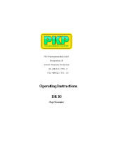
2. Function
PKP Flow-Switches and Flow-Meters of the described
types work on the principle of dynamic pressure.
The flow medium works against a target plate (4), which
causes the system to swing against a tension spring (1).
A bellows system made from stainless steel (3) seals
the indicator and switch equipment against the flowing
liquid. Connection between the target plate and the
evaluating system is made by a lever arm. A mi-
croswitch (2) is actuated whenever the preselected low
or high flow switch-points are passed.
Depending from type additionally a control-lamp and a
indication system for the actual flow will be actuated.
Je nach Gerätetyp wird zusätzlich eine Kontrollampe
oder ein Zeigerwerk zur Anzeige des Momentan-
durchflusses betätigt.
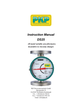
3.4 Mounting at the tube
3.4.1 Items with welded socket
The complete flange with screws and
sealing is delivered with the instru-
ment.
The distance 60mm has to be kept ex-
actly, because this directly affects the
calibration of the instrument.
Drill a ridgeless hole in the pipe and
weld on the socket.
Use the enclosed sealing.
Please keep the flow direction in con-
sideration during mounting procedure
(arrow).
The pipe must be free from pollution.

Operation Manual
Flow-Switch Type DP05
Flow-Meter Type DP06
03.01.00
V0102
3.4.2 Items with tread connection
We recommend sealing all threads with PTFE sealing tape. Ensure no excess of tape is left protruding
into the pipe.
3.4.3 Items with flange connection
A approved flange seal or gasket must be used. Neither this nor the required fixing bolts are included in the
delivery.
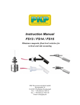
Circuit diagram type DP05 / DP06
Circuit diagram type DP05-EX / DP06-EX
4. Electrical connection
4.2 Connecting Type DP05 and DP06
Removing the enclosure to gain access to
the four polar connector block.
Additionally to the micro-switch a control
lamp is installed. This lamp is for optical
control of switch status of the micro-switch.
The current which is necessary for the lamp
is indicated at the label. The max. switching
performance is up to 230V/10A AC.
Please connect the device to ground with
help of the screw near cable entry .
4.3 Connecting Type DP05-EX and DP06-EX
The device will be connected at the end of
the cable. The connection must be done in
a area which is not endangered by explo-
sion (use EX cable gland), or in a special
EX connection enclosure.
The max. switching performance is up to
230V/10A AC.

04.06.98
Seite 3
Operation Manual
Flow-Switch Type DP05
Flow-Meter Type DP06
5. Calibration dates
Calibration dates, type of device and serial number are indicated at the label. Changes of medium, pressure
and position of mounting will influence accuracy.
6. Switch-point
Type DP05 Alternations of the switchpoint can be made by the customer within the limits indi-
cated on the scale.
Type DP06 Alternations of the switchpoint can be made by the customer within the limits indi-
cated on the scale.
The actual flow is indicated at front side of the unit.
7. Maintenance.
The mentioned PKP instruments are almost maintenance-free. In case of mal-function first of all check the
pipe system for calcification or other obstruction.
For cleaning do not use sharp-edged tools. Damaged instruments can only be repaired in our factory, be-
cause they have to be re-calibrated.
Damaged items should send back to the manufacturer because it is only there possible to do the re-
calibration which is necessary.
Unscrewing screws, changing tension spring or bellow system changes calibration and will invalidate the
guarantee.
Technical modifications reserved

1/08
68
Flow Metering and Monitoring Systems
DP05
Paddle-bellows flow switch
for liquids, with
variable switching point
• Easy switch-point adjustment
over the entire switching range
• Bellows keeps liquid hermetically
separated from the switching element
• Insensitive to dirty/contaminated
fluids
• Very high reliability
• High electrical loading capacity
through use of 1 or 2 independently
adjustable microswitches
• Insensitive to electromagnetic fields
• Easy installation,
for piping up to DN 600
Description:
The flow switches model DP05 operate according to paddle-
bellows principle. The flowing liquid pushes against the sur-
face area of a paddle mounted at the end of a pivoting arm.
The arm is deflected against the force of a spring. This de-
flection is mechanically transmitted to an adjustable contact
unit. A bellows systems hermetically seals the liquid off from
the mechanism.
In case of malfunction, the spring returns the paddle plate to
the zero position (no flow), which causes the system to auto-
matically signal a fault.
Fields of application:
The DP05 paddle-bellows flow switch is suitable for
monitoring thin and low-viscosity liquids in average to large
flow volumes. For nominal pipe sizes over DN50, installation
with a special intermediate mounting flange yields a price/
performance ratio of exceptional economy.
PKP Process Instruments Inc.
10 Brent Drive · Hudson, MA 01749
SS+1-978-212-0006 · TT+1-978-568-0060
Email: [email protected] · Internet: www.pkp.eu
PKP Prozessmesstechnik GmbH
Borsigstraße 24 · D-65205 Wiesbaden
SS+49 (0) 6122-7055-0 · TT+49 (0) 6122-7055-50
Email: [email protected] · Internet: www.pkp.de

69
Dimensions
DP05.R...
Dimensions
DP05.F...
Dimensions
DP05.A...
Ordering Code:
Order number: DP05. R025. B. 1. 20-100
Paddle-bellows flow switch
Process connection (xx=nominal pipe size):
R0xx = With male thread
(G 3/8 to G2 only)
F0xx = With flange
(DN10 to DN50 only)
Axxx = With weld-on flange
(from DN65 to DN600)
Material combination:
A = Brass / stainless steel (galvanized steel)
B = Completely of stainless steel
C = PVC / stainless steel (not for DP05.A..).
Switching output:
1 = 1 microswitch (250 V / 10 A)
2 = 2 microswitch (250 V / 5 A)
Switching range:
xxxx-xxxx = min. - max. switching point (refer to „Measuring Ranges” table)
Additional specifications:
• Liquid density and viscosity (if not water)
• Process pressure and temperature
• Mounting position and direction of flow
• Ratings of electrical connections
Process
connection
DP05.R...
DP05.F...
Flow rate
(l/min)
min. max. min. max.
Flow rate
(m3/h)
Process
connection
DP05.A...
Switching ranges apply to water at
20°C. Within the specified limits, all
switching ranges can be achieved,
provided that the max./min. ratio for
the switching point is not exceeded.
3/8"/ DN10 1 25 1:5 DN 65 4,8 60 1:4
1/2"/ DN15 1 55 1:5 DN 80 7,2 90 1:4
3/4"/ DN20 5 100 1:5 DN 100 12 144 1:4
1"/ DN25 6 150 1:5 DN 125 18 255 1:4
11/4"/ DN32 10 250 1:5 DN 150 24 330 1:4
11/2"/ DN40 20 400 1:5 DN 200 42 600 1:4
2"/ DN50 50 600 1:5 DN 250 72 900 1:4
DN 300 102 1.200 1:4
DN 350 150 1.800 1:4
DN 400 180 2.400 1:4
DN 500 300 3.600 1:4
DN 600 420 4.500 1:4
Flow
ratio
Flow
ratio
3/8"/ DN10 135 155 145
1/2"/ DN15 135 155 145
3/4"/ DN20 135 160 145
1"/ DN25 135 160 145
1 1/4"/ DN32 170 190 150
1 1/2"/ DN40 170 190 155
2"/ DN50 170 190 160
Nominal size Installation length Z (in mm) installation
DP05.R... DP05.F... clearance H
(in mm)
Technical specifications:
Max. pressure: 16 bar
Max. temperature: 100 °C
Repeat accuracy: +/- 5% to 20 l/min
+/- 4% from 21 to 200 l/min
+/- 3% > 200 l/min
Switching hysteresis: 10% (to 2 bar)
Contacts: microswitch, 250 V, 10 A or 5 A
Status display: low-voltage lamp or LED
(depends on the voltage rating)
Measuring ranges:
Designs:
Each of the 3 types of DP05 flow switches are available
in 3 material combinations:
DP05.R... with T fitting and pipe-thread connection
from G 3/8 to G 2 male thread
DP05.F... with T fitting and DIN flange from DN10
to DN50
Material T fitting of brass
combination A: Pivoting system of brass
Bellows of 1.4571 stainless steel
Flange of galvanized steel
Material T fitting of 1.4571 stainless steel
combination B: Pivoting system of 1.4305
stainless steel
Bellows of 1.4571 stainless steel
Flange of 1.4571 stainless steel
Material T fitting of PVC
combination C: pivoting system of 1.4305 stainless steel
Bellows of 1.4571 stainless steel
Flange of PVC
DP05.A… with weld-on flange for nominal
pipe size DN65 to DN600
Material Housing of brass
combination A: Pivoting system of brass
Bellows of 1.4571 stainless steel
Weld-on flange of carbon steel, painted
Material Housing of 1.4571 stainless steel
combination B: Pivoting system of 1.4305 stainless steel
Bellows of 1.4571 stainless steel
Weld-on flange of 1.4571 stainless steel
Dimensions:
PKP Process Instruments Inc.
10 Brent Drive · Hudson, MA 01749
SS+1-978-212-0006 · TT+1-978-568-0060
Email: [email protected] · Internet: www.pkp.eu
PKP Prozessmesstechnik GmbH
Borsigstraße 24 · D-65205 Wiesbaden
SS+49 (0) 6122-7055-0 · TT+49 (0) 6122-7055-50
Email: [email protected] · Internet: www.pkp.de

PKP Prozessmesstechnik GmbH · Borsigstraße 24 · D-65205 Wiesbaden-Nordenstadt
Tel.: +49 (0) 6122-7055-0 · Fax: +49 (0) 6122-7055-50
e-mail: [email protected] · homepage: www.pkp.de
1/08
70
Flow Metering and Monitoring Systems
DP06
Paddle-bellows flow meter
and switch for liquids
• Large 270° dial gauge display
for flow rate
• Simple switch-point adjustment
over the entire switching range
on a separate small dial
• Bellows keeps liquid hermetically
separated from the switching element
• Insensitive to dirty/contaminated
fluids
• Very high reliability
• High electrical loading capacity
through use of 1 or 2 independently
adjustable microswitches
• Insensitive to electromagnetic fields
• Easy installation, for piping up to
DN 600
Description:
The flow meters and switches model DP06 operate accor-
ding to the paddle-bellows principle. The flowing liquid
pushes against the surface area of a paddle mounted at
the end of a pivoting arm.
The arm is deflected against the force of a spring. This de-
flection is mechanically transmitted to a 270° dial-gauge dis-
play and a separately adjustable contact unit.
A bellows system seals the liquid off from the mechanism.
In case of malfunction, the spring returns the paddle plate
to the zero position (no flow), which causes the system to
automatically signal a fault.
Fields of application:
The DP06 paddle-bellows flow meter and switch is suitable
for monitoring thin and low-viscosity liquids in average
to large flow volumes. For nominal pipe sizes over DN50,
installation with an intermediate mounting flange yields a
price/performance ratio of exceptional economy.

PKP Prozessmesstechnik GmbH · Borsigstraße 24 · D-65205 Wiesbaden-Nordenstadt
Tel.: +49 (0) 6122-7055-0 · Fax: +49 (0) 6122-7055-50
e-mail: [email protected] · homepage: www.pkp.de
71
Ordering Code:
Order number: DP06. R025. B. 1. 20-
100
Paddle-bellows flow meter and switch
Process connection (xx=nominal pipe size):
R0xx = With male thread
(G 3/8 to G2 only)
F0xx = With flange
(DN10 to DN50 only)
Axxx = With weld-on flange
(from DN65 to DN600)
Material combination:
A = Brass / stainless steel (carbon steel, galvanized)
B = Completely of stainless steel
C = PVC / stainless steel (not for DP06.A..).
Switching output:
1 = 1 microswitch (250 V / 10 A)
2 = 2 microswitch (250 V / 5 A)
Switching range:
xxxx-xxxx = min. - max. flow rate (refer to „Measuring Ranges” table)
Additional specifications:
• Liquid density and viscosity (if not water)
• Process pressure and temperature
• Mounting position and direction of flow
• Ratings of electrical connections
Process
connection
DP06.R...
DP06.F...
Flow rate
(l/min)
min. max. min. max.
Flow rate
(m3/h)
Process
connection
DP06.A...
Switching ranges apply to water at 20
°C. Within the specified limits, all
switching ranges can be achieved,
provided that the max./min. ratio for
the switching point is not exceeded.
3/8"/ DN10 1 25 1:5 DN 65 4,8 60 1:4
1/2"/ DN15 1 55 1:5 DN 80 7,2 90 1:4
3/4"/ DN20 5 100 1:5 DN 100 12 144 1:4
1"/ DN25 6 150 1:5 DN 125 18 255 1:4
11/4"/ DN32 10 250 1:5 DN 150 24 330 1:4
1 1/2"/ DN40 20 400 1:5 DN 200 42 600 1:4
2"/ DN50 50 600 1:5 DN 250 72 900 1:4
DN 300 102 1.200 1:4
DN 350 150 1.800 1:4
DN 400 180 2.400 1:4
DN 500 300 3.600 1:4
DN 600 420 4.500 1:4
Flow
ratio
Flow
ratio
3/8"/ DN10 135 155 145
1/2"/ DN15 135 155 145
3/4"/ DN20 135 160 145
1"/ DN25 135 160 145
1 1/4"/ DN32 170 190 150
1 1/2"/ DN40 170 190 155
2"/ DN50 170 190 160
Nominal size Installation length Z (in mm) installation
DP06.R... DP06.F... clearance H
(in mm)
Technical specifications:
Max. pressure: 16 bar
Max. temperature: 100 °C
Repeat accuracy: +/- 5% to 20 l/min
+/- 4% from 21 to 200 l/min
+/- 3% > 200 l/min
Switching hysteresis: 10% (to 2 bar)
Contacts: microswitch, 250 V, 10 and, or 5 A
Status display: low-voltage lamp or LED
(depending on the voltage rating)
Measuring ranges:
Designs:
Each of the 3 types of DP06 flow meters and switches
are available in 3 material combinations:
DP06.R... with T fitting and pipe-thread connection
from G 3/8 to G 2 male thread
DP06.F... with T fitting and DIN flange from
DN10 to DN50
Material T fitting of brass
combination A: Pivoting system of brass
Bellows of 1.4571 stainless steel
Flange of galvanized carbon steel
Material T fitting of 1.4571 stainless steel
combination B: Pivoting system of 1.4305 stainless steel
Bellows of 1.4571 stainless steel
Flange of 1.4571 stainless steel
Material T fitting of PVC
combination C: Pivoting system of 1.4305 stainless steel
Bellows of 1.4571 stainless steel
Flange of PVC
DP06.A... with weld-on flange for nominal
pipe size DN65 to DN600
Material Housing of brass
combination A: Pivoting system of brass
Bellows of 1.4571 stainless steel
Weld-on flange of carbon steel, painted
Material Housing of 1.4571 stainless steel
combination B: Pivoting system of 1.4305 stainless steel
Bellows of 1.4571 stainless steel
Weld-on flange of 1.4571 stainless steel
Dimensions:
Dimensions
DP06.R...
Dimensions
DP06.F...
Dimensions
DP06.A...
/