
Installation and
operating instructions
Bypass Level Indicator
BM 26 A
For level or interface
measurement of liquids
© KROHNE 11/2016 7.02186.28.00
KSAS
Variable area flowmeters
Vortex flowmeters
Flow controllers
Electromagnetic flowmeters
Ultrasonic flowmeters
Mass flowmeters
Level measuring instruments
Communications engineering
Engineering systems & solutions
Switches, counters, displays and recorders
Heat metering
Pressure and temperature
Subject to change without notice.

2 Installation and Operating Instructions BM 26 A
Contents
General advice on safety ............................................................................................................. 4
Description: BM 26 A bypass level indicator with magnetic flaps or bar scale ..................... 4
Documentation symbols ............................................................................................................. 5
Handling ....................................................................................................................................... 5
Product liability and warranty ..................................................................................................... 5
Items supplied .............................................................................................................................. 5
Standards / Approvals ................................................................................................................. 6
Official approvals and certificates ............................................................................................. 7
Principal gauge components ...................................................................................................... 7
1 Installation ......................................................................................................................... 8
1.1 Packing and storage ................................................................................................... 8
1.2 BM 26 A construction details .................................................................................... 10
1.3 Mechanical installation requirements ........................................................................ 12
1.4 Mounting on the tank ................................................................................................ 13
1.5 Start-up procedure .................................................................................................... 14
1.6 True level indication .................................................................................................. 15
1.6.1 Level measurement using the local indicator and scale ...................................... 15
1.6.2 Floats .................................................................................................................. 16
1.6.3 Changing the process conditions ........................................................................ 18
1.6.4 Correcting the scale position to accurately read true liquid level ........................ 20
1.6.5 Functional check of local level display (bar indicator only) .................................. 22
2 Level transducer ............................................................................................................. 23
2.1 General notes ........................................................................................................... 23
2.2 Transmitters .............................................................................................................. 24
2.2.1 Transmitter versions for the BM 26 A ................................................................. 24
2.2.2 Electrical connections ......................................................................................... 24
3 Limit switches / contacts ................................................................................................ 26
3.1 General notes ........................................................................................................... 26
3.2 Designation code for defining limit switch versions ................................................... 26
3.3 Limit switch options for the BM 26 A (non-Ex) .......................................................... 26
3.4 Limit switch options for the BM 26 A (ATEX version) ................................................ 27
3.5 How to use a limit switch........................................................................................... 27
3.5.1 Operating principle .............................................................................................. 27
3.5.2 Installation ........................................................................................................... 27
3.5.3 Overall dimensions of limit switches mounted on measuring tube ...................... 29
3.5.4 Limit switch dimensions (without bracket and clamp) ......................................... 30
3.5.5 Electrical connections ......................................................................................... 31
3.6 Fine adjustments to the limit switch trigger point ...................................................... 33
3.6.1 General notes ..................................................................................................... 33
3.6.2 Fine adjustments to the limit switch trigger point ................................................ 33
3.6.3 Switching point diagram and offset values for limit switches ............................... 34

Installation and Operating Instructions BM 26 A 3
4 Special versions ............................................................................................................. 35
4.1 Low-temperature versions AG, TR or IC/TR ............................................................. 35
4.2 High-temperature versions HR or IC/HR .................................................................. 35
4.3 Heating system for measuring tube BM 26 A/B ........................................................ 36
4.4 Liquid/liquid interface measurement BM 26 A/TS ..................................................... 36
5 Maintenance .................................................................................................................... 37
6 Ordering spare parts ...................................................................................................... 37
7 Technical data ................................................................................................................. 38
7.1 Technical data: BM 26 A .......................................................................................... 38
7.2 Technical data: level transmitter modules ................................................................ 40
7.3 Technical data: limit switches ................................................................................... 41
7.4 Guide tube assembly materials ................................................................................ 42
7.4.1 Maximum operating conditions for BM 26 A with 316Ti steel measuring tube .... 42
7.4.2 Flange categories for operating conditions in a 316Ti steel measuring tube ...... 42
7.4.3 Maximum operating conditions for BM 26 A with 316 L steel measuring tube .... 43
7.4.4 Flange categories for operating conditions in a 316L steel measuring tube ....... 43
7.5 BM 26 A weights and dimensions............................................................................. 44
7.5.1 Weights .............................................................................................................. 44
7.5.2 Indicator dimensions ........................................................................................... 44
7.5.3 Overall dimensions of measuring tube classes (with loose or welding neck flanges)
……………….. .................................................................................................... 44
7.5.4 Distance of welding neck flange raised facing from measuring tube axis ........... 47
8 Measuring principle ........................................................................................................ 48
If you need to return level gauges for testing or repair to KROHNE ..................................... 51

4 Installation and Operating Instructions BM 26 A
General advice on safety
This manual gives a complete set of instructions for the installation, operation and maintenance of
the ATEX version of the BM 26 A Bypass Level Indicator.
This instrument is designed to function at near constant pressure conditions.
The instrument must be installed and used by suitably qualified personnel.
Our conformity declaration is limited to the parts of the level indicator that are under pressure,
excluding parts that may be dismantled (e.g. valves).
Events that are not taken into account in the calculations include: exceptional risks such as
earthquakes, bad weather, acts of destruction (such as sabotage, terrorism, vandalism, etc.) and
fire.
WARNING
Special measures must be taken when using titanium floats in order to avoid
friction between the titanium and stainless steel causing sparks in an inflammable
gaseous environment.
The standard design calculation does not take into account the theoretical
coefficient of corrosion. The product circulating in the vessel must not have
properties that give rise to surface erosion.
Ex-approved devices: If the device has the appropriate options, then special
regulations are applicable to the use of equipment in hazardous locations. These
regulations are described in this booklet. For more data, refer to the Ex certificate
supplied with the device.
Description: BM 26 A bypass level indicator with magnetic flaps or bar scale
The BM 26 A bypass level indicator is used for measuring level, interface or volume in open or
pressurized tanks. It is mounted adjacent to the tank and uses the principle of communicating
vessels – the liquid level in the measuring tube corresponds to the liquid level in the tank. Due to its
design, the unit is suitable for use in connection with corrosive, toxic or flammable substances and in
severe service conditions.
The local indicator consists of:-
A bar indicator (follower magnet) in a Pyrex glass tube as standard
or a flap indicator (yellow/black magnetic flaps) in a Pyrex glass tube.
No power is required for local liquid-level indication.
Optionally, the unit can be equipped or retrofitted with an electrical analogue level transducer
system and/or limit switches.
Use in hazardous areas
The BM 26 A bypass level indicator is approved for use in explosive atmospheres when equipped
with the appropriate options. It is imperative that the approval certificate details and boundary
conditions are observed.

Installation and Operating Instructions BM 26 A 5
Documentation symbols
CAUTION
Information that, if not followed, may lead to actions resulting in incorrect
functioning of the device.
WARNING
Information that, if not followed, may lead to actions resulting in measurement
error, personal injury and/or damage to the device.
Information and instructions for Ex applications
Information that must be used to observe the safety requirements for installation,
operation and maintenance in hazardous areas. If instructions are not followed, this
may result in personal injury, damage to the device and/or incorrect functioning of
the device.
Handling
WARNING
The device normally weighs from 14.5 kg or 32 lb to 40 kg or 88 lb. Carry the
device using at least two people, lifting it by the process connections. Lifting gear
may also be used but no attempt should be made to lift the device by the
measuring scale, level transducer or other attached equipment.
Product liability and warranty
The BM 26 A bypass level indicator is designed exclusively for liquid-level, liquid/liquid interface or
volume measurement, depending on the scale and float selected by the customer.
Special codes and regulations apply to its use in hazardous areas.
Responsibility as to suitability and intended use of this bypass level indicator rests solely with the
operator.
Improper installation and operation of these bypass level indicators may lead to loss of warranty.
In addition, the “General conditions of sale” forming the basis of the purchase contract are
applicable.
If the bypass level indicator needs to be returned to KROHNE, please read and follow the
instructions given at the end of this manual.
Items supplied
BM 26 A bypass level indicator option: with or without current output or limit switches
These installation and operating instructions
Approval documents / certificates of conformity (for hazardous duty only)
Supplied without mounting accessories (stud bolts, flange gaskets and wiring to be provided by
customer).

6 Installation and Operating Instructions BM 26 A
Special certificates (Optional: supplied on customer demand only)
Test certificate to EN 10204: pressure test, dye penetration test, radiographic test, leak-tightness
test, ultrasonic test, helium leak test, surface cleanness and material
Standards / Approvals
In compliance with European Directive 2014/34/EU, the bypass level indicators
described in these instructions conform to European Standards EN 13463-1,
EN 50014 +1 +2, EN 50018, EN 50020 and EN 50284 and are certified for use in
hazardous locations by the INERIS certification agency under INERIS
02ATEX0088X when equipped with the appropriate options.
WARNING
The details given in this approval certificate together with its boundary conditions
must be observed.
This instrument also conforms to the European Union Pressure Equipment Directive (PED)
2014/68/EU.
Ex Safety Instructions
ATEX-certified BM 26 A level indicators can be used in explosive atmospheres of all flammable
substances in Gas Group IIC (with the exception of cases given in these instructions) and
applications requiring Category 1/2 G and 1G equipment. The instrument must be installed and used
by suitably qualified personnel.
Ex Equipment Category Definitions
Category 1/2 G – instruments
(for applications where the Ex d-rated explosion-proof box is used)
The signal converter for current output and limit switch options are located in hazardous areas
requiring instruments qualified as being category 2. The process connection and tank wall form an
interface between zones for category 1 and 2 equipment. The indicator measuring elements (float
and measuring tube) are qualified as being category 1. The G rating means that the instrument is
qualified for gas environments.
Category 1 G - instruments
The signal converter for current output, limit switch options and measuring components are located
in hazardous areas requiring instruments qualified as being category 1.

Installation and Operating Instructions BM 26 A 7
Official approvals and certificates
Application
Approved by
Instrument version
Certification mark
ATEX certification
INERIS
BM 26 A
Certificate no.
INERIS 02ATEX0088X*
*This EC-type Examination Certificate is available on KROHNE’s download centre webpage on
http://www.krohne.com.
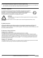
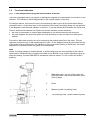
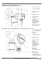
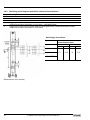
Principal gauge components
1
Level
transducer
(cable gland
not supplied)
2
Process
connections
3
Measuring tube
(bypass
chamber)
containing float
loaded with
magnets
4
MS 15 /EXD
limit switch
(cable gland
not supplied)
5
MS 15 /STD or
/EXI limit switch
6
Scale clamped
adjacent to
measuring tube
integrating a
Pyrex tube with
float-following
indicator bar.

8 Installation and Operating Instructions BM 26 A
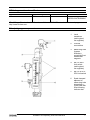
1 Installation
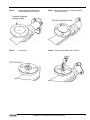
1.1 Packing and storage
Floats packed separately
1
To install, remove the bottom flange and insert the float – the right way up – into the guide
chamber.
2
Align gaskets.
3
Tighten nuts using the correct torque with regards to the strength of bolts specified for the
vessel pressure rating, connecting flange and material.
CAUTION
Make sure that the guide tube is free of foreign bodies
(dirt, loose objects, etc.).
Floats held in position during transit by a plastic locking clip
This should be removed from the guide tube before installation through the bottom connection
flange. Follow the procedure below:
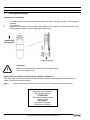
Step 1
Check measuring tube for a red sticker next to the bottom process connection.
ATTENTION!
Retirer la tige de sécurité
maintenant le flotteur
ATTENTION !
Take away transport safety
device for float
ACHTUNG !
Transportsicherung für
Schwimmer entfernen

Installation and Operating Instructions BM 26 A 9
Step 2
Undo adhesive tape around
bottom process connection
Step 3
Remove process connection plastic
protective cover
Step 4
Locate clip
Step 5
Remove clip with a pair of pliers

10 Installation and Operating Instructions BM 26 A
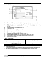
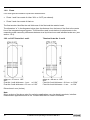
1.2 BM 26 A construction details
The diagram below shows a standard BM 26 A/C/RR without level transducer and switch options
1
Vent plug
2
Measuring tube
3
Red triangle reference mark giving
factory-calculated zero position of
measuring scale
4
Glass tube for indicator
5
Scale
6
Float (magnets mounted in lower half)
7
Liquid level
8
Mid-point of indicator
9
Indicator (standard follower bar)**
10
Zero point of measurement
(centreline of lower connecting flange)
11
Scale zero
12
Stop (red KROHNE plate)
13
Instrument nameplate
* optional flap indicator available (see section 8)
Details:
Item 12 – The red KROHNE plate at the bottom of the scale (item 5) has a label listing the technical
characteristics of the float (engineering drawing number, maximum allowable working pressure (PS),
test pressure (PE) and float material). For example :

Installation and Operating Instructions BM 26 A 11
Item 13 – BM 26 A nameplate
1
Date of manufacture (Year-Month-Day)
2
Devices with Ex approval only: Equipment approval category (explosive atmosphere –
gas), types of device protection including approved Gas Groups and temperature classes
3
PED marking. Refer to the table that follows for the conditions for each marking (no marking,
PED/G1/III, PED/G1/IV or PED/G2/III). This marking agrees with NAMUR Recommendation
NE 080.
4
Maximum allowable working temperature (Ts)
5
Test pressure (Pt)
6
Maximum allowable working pressure (Ps)
7
Measuring tube volume (litres)
8
Customer tag number
9
Factory serial number
10
Type code (e.g. BM26 A / C / RR / ER / K) *
11
Designation code as given in the options list (VF06…) **
12
Devices with Ex approval only: ATEX certification agency code (0344)
13
PED certification agency code (0036 – if there is a PED marking in item 3)
14
Model name and number
* Item 3 – PED marking:
Condition
PED marking
PED certification
agency code (item 13)
Group 1 fluids
Ps (bar) × Volume (L) ≤ 1000
PED/G1/III
0036
Ps (bar) × Volume (L) > 1000
PED/G1/IV
0036
Volume ≤ 1 L and Ps ≤ 200 bar, or
Ps (bar) × Volume (L) ≤ 25
—
—
Group 2 fluids
Ps (bar) × Volume (L) ≤ 3000
PED/G2/III
0036
** Type code is defined as:
Product code/Process connections/Material code/Design/Level transducer/Contact/Approval
*** See BM 26 A technical data sheet for a list of standard options and designation codes

12 Installation and Operating Instructions BM 26 A
Item 10 – Type code
Type code element
Code
Code definition
Product code
BM 26 A
Bypass Level Indicator (A model)
Process connections
C
D
E
F
Two lateral connections
Two axial connections
One top lateral entry and one bottom axial exit
One bottom lateral entry and one top axial exit
Construction material code
RR
Stainless steel
Design
No info
B
AG
IC/TR
IC/HR
Standard design
Heater
Anti-freeze version -40°C / -40°F
With low temperature insulation
With high temperature insulation
Level transducer
No info
ER
Without level transducer
With level transducer
Contact
No info
K
Without limit switches
With limit switches
Approval
No info
EXI
EXD
Standard, no approval
For EEx – intrinsically safe applications
For EEx – flameproof applications
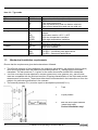
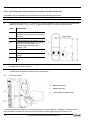
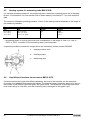
1.3 Mechanical installation requirements
Ensure that the requirements given below have been followed:
The effective pressure of the installation (the maximum permitted by the pressure limiting valve)
must never be greater than the maximum permitted pressure, Ps, marked on the instrument
nameplate. The test pressure, Pt, is given on the order documents and BM 26 A nameplate.
The user must be sure that materials in contact (guide tube, float, gaskets, etc.) with the fluid
used are compatible with the fluid and conform to ageing characteristics of the fluid used and the
measurement environment. These have either been recommended in the instructions or form the
subject of a particular specification in the contract.
The external pressure (Pext) must be equal to atmospheric pressure(Patmos).
1
Tank
2
Liquid product
3
BM 26A level-liquid indicator
(measuring tube):
Vertical installation only!

Installation and Operating Instructions BM 26 A 13
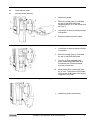
1.4 Mounting on the tank
The BM 26 A bypass level indicator must be installed vertically on the tank
When installing the BM 26 A bypass level indicator with or without the electrical level transducer
system, make sure that any magnetic fields generated by other equipment will not affect
measurements.
Select bolts and gaskets (supplied by customer) that correspond to the pressure rating of the
connecting flange and the operating pressure.
The process connections (flanges) must fit perfectly, i.e. they must be centred, parallel and
bolted in a professional way, in order to avoid unnecessary mechanical stress on the installation.
The tank must be free of contaminants. It is recommended to install shut-off elements, e.g.
cocks, valves, etc., between the tank and bypass level indicator to allow the bypass level
indicator to be cleaned independently of the tank. The drain plug in the bottom flange must also
be replaced by a drainage cock with discharge line.
1
Shut-off valve (top and bottom)
2
Drainage valve with discharge tube.
3
Vent plug

14 Installation and Operating Instructions BM 26 A
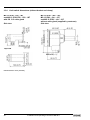
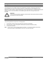
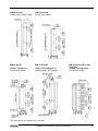
Additional anchoring points between the BM 26 A and the tank are recommended for very high
installations (above 6 metres length for stainless steel). The standard anchor is a set of collars
attached to a plate. This is available on demand from KROHNE. See figure below for side and
plan view and dimensions in millimetres and inches.
(1) Chamber collar (2 collars)
(2) Plate for bolting to the tank
Dimensions
[mm]
[inches]
a
73
2.87
b
3
0.12
c
52
2.05
d
28.5
1.12
e
4
0.16
Øf
8.4
0.33
Øg
15
0.59
h
15
0.59
j
50
1.97
k
80
3.15
m
26
1.02
n
12
0.47
o
4
0.16
p
16.5
0.65
q
64.85
2.55
r
34.64
1.36
s
33
1.31
t
4
0.16
u
58
2.28
1.5 Start-up procedure
WARNING
Take the necessary safety precautions when working with
pressurized tanks.
Step
Action
1
Close drainage plugs and/or drainage cock.
2
Open shutoff elements at lower and upper connecting flange.
3
Adjust the position of the local measuring scale so that scale
level corresponds exactly to true level, see section 1.6.
WARNING
The user must take the necessary steps to protect the installed instrument from
shock waves (water hammer). A pressure limiting valve must equally protect the
installation.
The instrument must regularly undergo servicing to conform to the rules and
regulations applicable to the site that it is installed on.
High Temperature versions - precautions must be taken to avoid burns to
operators.

Installation and Operating Instructions BM 26 A 15
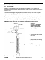
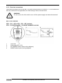
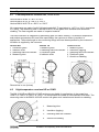
1.6 True level indication
1.6.1 Level measurement using the local indicator and scale
The float is equipped with a ring system of permanent magnets for transmission of liquid level to the
indicator. The indicator is linked magnetically to the magnet system in the float.
For design reasons, the minimum level in the measuring tube is given by the lower lateral flange
connection axis i.e. liquid level zero is the centreline of the lower connecting flange. As can be seen
in the diagram of the float and indicator in section 1.2, the bar follows the float below the liquid level.
There is a difference between true liquid level and the indicator position because:
the float is immersed to a certain depth depending on the product density and float type,
the float magnets are positioned below the float centreline in order for the float to have good
stability.
The scale is delivered correctly set up for measuring the product specified in the order. The red
reference mark at the top of the measuring tube (item 1 in the diagram below) shows where the top
of the scale must be clamped for the indicator to give an accurate reading of liquid level. No further
adjustment is necessary when the gauge is commissioned.
Note
If there is a large change in product density, a product other than the one specified in the order is
measured or a different float is installed, the scale on the BM 26 A may require adjusting to give an
accurate reading. Contact KROHNE for assistance (see also section 1.6.4 to correct the scale’s
position).
1
Reference mark : the top of the upper red
KROHNE plate must touch the bottom point
of the triangle
2
Scale
3
Measuring tube (containing float)
4
Top clamping collar ( scale-measuring tube)

16 Installation and Operating Instructions BM 26 A
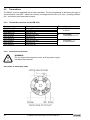
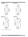
1.6.2 Floats
Four float types are used for liquid level measurement.
Floats 1 and 2 are made of either 316L or 316Ti (as ordered).
Floats 3 and 4 are made of titanium
The float number identifies the wall thickness of the float and the material used.
The dimension “a” in the diagrams below gives the distance from the base of the float to the centre
line of the integrated magnet system. This should be used in calculations for adjustments to the
measuring scale caused by differences between true liquid-level zero and indicated scale zero (see
section 1.6.4).
316L or 316Ti floats-No.1 and 2
Titanium floats-No. 3 and 4
where a = 47 mm or 1.85“
where a = 48 mm or 1.89“
and :
Float No.1 wall thickness = 1 mm or 0.04”
Float No.2 wall thickness = 0.5 mm or 0.02”
and :
Float No.3 wall thickness = 0.6 mm or 0.024”
Float No.4 wall thickness = 1 mm or 0.04”
Dimensions in mm (inches)
Note
Minor variants of the above exist for particular applications: very low density products, interface
measurement applications and so on. Contact KROHNE for further information.

Installation and Operating Instructions BM 26 A 17
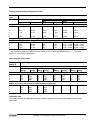
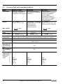
Density and operating temperature limits
Float
type
Density and operating temperature limits
No.
Min. density of product
Product temperature
Min.
Max.
[kg/l]
[lb/ft3]
[°C]
[°F]
[°C]
[°F]
BM 26 A / Standard versions without approvals
1
0.82
51.19
-200
-325
+300
+570
2
0.55
34.34
-200
-325
+300
+570
3
0.50
31.21
-200
-325
+300
+570
4
0.60
37.46
-200
-325
+300
+570
Instruments or approved for use in Ex hazardous zones
BM 26 A / ATEX (local indicator with electrical equipment)
1
0.82
51.19
-40
-40
+70…+195*
+160…+380*
2
0.55
34.34
-40
-40
+70…+195*
+160…+380*
3
0.50
31.21
-40
-40
+70…+195*
+160…+380*
4
0.60
37.46
-40
-40
+70…+195*
+160…+380*
* The product temperature depends on the BM 26 A ATEX temperature class (T3 … T6). See
section 7.1 for further information.
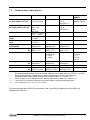
Operating pressure limits
Float type
BM 26 A
Operating pressure limits of the float
No.
Max. allowable operating pressure
At +20°C / +70°F
At +100°C /+210°F
At +200°C / +390°F
At +300°C / +570°F
[barg]
[psig]
[barg]
[psig]
[barg]
[psig]
[barg]
[psig]
Standard versions without approvals
1
55
800
41
600
37
535
32
465
2
23
335
12
175
10
145
9
130
3
23
335
13
190
10
145
8
115
4
55
800
31
450
24
350
19
275
Instruments approved for use in Zone 0
BM 26 A/ATEX (local indicator with electrical equipment)
1
55
800
41
600
–
–
–
–
2
23
335
12
175
–
–
–
–
3
23
335
13
190
–
–
–
–
4
55
800
31
450
–
–
–
–
Important note
Float test pressure is tested according to pressure equipment directive 2014/68/EU and official
approvals.

18 Installation and Operating Instructions BM 26 A
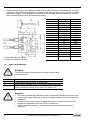
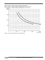
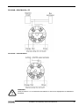
1.6.3 Changing the process conditions
If the user wishes to use the BM 26 A to measure another product, then the following points should
be noted:
Contact KROHNE for advice and information on equipment / product compatibility especially
where use in hazardous areas is concerned.
Ensure that Pressure Equipment Directive 2014/68/EU is observed, if relevant.
The depth of immersion “c” (see section 1.6.4) of the float increases as product density
decreases. This depth is also dependent on the float model (No. 1, 2 ,3 or 4) and material used
(316L, 316Ti or titanium). The new depth of immersion “c” is shown on the two line graphs
below. Further information is available from KROHNE on request to accurately calibrate your
instrument. When contacting KROHNE remember to:
−
quote KROHNE references (order / fabrication no.) for the BM 26 A in question
−
identify the new product and give its density at the new operating conditions.
−
give information about the old application. Floats may have been especially adapted
for specific applications; for example: density- adjusted (pressurized) or floats for low
density applications and floats with ballast for interface measurement.
The top of the float must be no more than 35 mm or 1.38” above the product surface to ensure
reliable floatability and accurate measurement.
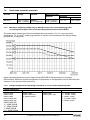
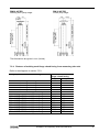
Graph 1: Float immersion depth against product density
Line 1 : Float no. 1 made of 316Ti (1.4571) or 316L (1.4404), wall thickness 1 mm or 0.04”
Line 2 : Float no. 2 made of 316Ti (1.4571) or 316L (1.4404), wall thickness 0.6 mm or 0.02”
Where c is immersion depth and is product density

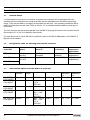
Installation and Operating Instructions BM 26 A 19
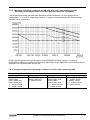
Graph 2: Float immersion depth against product density
Line 3 : Float no. 3 made of titanium, wall thickness 0.6 mm or 0.024”
Line 4 : Float no. 4 made of titanium, wall thickness 1 mm or 0.04”
Where c is immersion depth and is product density

20 Installation and Operating Instructions BM 26 A
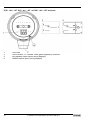
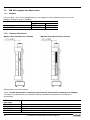
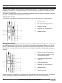
1.6.4 Correcting the scale position to accurately read true liquid level
The scale* can be corrected by the customer using the following procedure:
Step
Action
1
Find the float immersion depth “c” (supplied by KROHNE, refer also to section 1.6.3).
2
Subtract the dimension “a”, float base to magnet centreline (given on the float dimensioned
drawing in Section 1.6.2), from “c” to get the dimension “b”, scale correction factor.
Item
Description
b =
c – a (difference between liquid level
and indicator position due to product
density)
c =
float immersion depth (a function of
product density), see section 1.6.3.
a =
distance from centerline of magnet
system to the float base, see
dimensioned float drawings in
section 1.6.2.
1 =
Float
2 =
Follower magnet of indicator (or limit
switch)
3 =
Position of magnets mounted in the
float
3
Loosen the two clamp collars holding the measuring scale onto the measuring tube using a
screwdriver or 8 mm wrench.
4
Bring the zero point (top of the lower red KROHNE plate) on the scale into line with the
centreline of the bottom lateral process connection.
4a
Undo top collar
1
Measuring scale
2
Measuring tube
3
Top measuring scale collar
*This information also applies to the initial setting up of limit switches – however, the fitter should
also remember to take into account the limit switches offset trigger point (see section 3.6).
Page is loading ...
Page is loading ...
Page is loading ...
Page is loading ...
Page is loading ...
Page is loading ...
Page is loading ...
Page is loading ...
Page is loading ...
Page is loading ...
Page is loading ...
Page is loading ...
Page is loading ...
Page is loading ...
Page is loading ...
Page is loading ...
Page is loading ...
Page is loading ...
Page is loading ...
Page is loading ...
Page is loading ...
Page is loading ...
Page is loading ...
Page is loading ...
Page is loading ...
Page is loading ...
Page is loading ...
Page is loading ...
Page is loading ...
Page is loading ...
Page is loading ...
Page is loading ...
-
 1
1
-
 2
2
-
 3
3
-
 4
4
-
 5
5
-
 6
6
-
 7
7
-
 8
8
-
 9
9
-
 10
10
-
 11
11
-
 12
12
-
 13
13
-
 14
14
-
 15
15
-
 16
16
-
 17
17
-
 18
18
-
 19
19
-
 20
20
-
 21
21
-
 22
22
-
 23
23
-
 24
24
-
 25
25
-
 26
26
-
 27
27
-
 28
28
-
 29
29
-
 30
30
-
 31
31
-
 32
32
-
 33
33
-
 34
34
-
 35
35
-
 36
36
-
 37
37
-
 38
38
-
 39
39
-
 40
40
-
 41
41
-
 42
42
-
 43
43
-
 44
44
-
 45
45
-
 46
46
-
 47
47
-
 48
48
-
 49
49
-
 50
50
-
 51
51
-
 52
52


Ask a question and I''ll find the answer in the document
Finding information in a document is now easier with AI
Related papers
-
KROHNE OPTIMASS 7000 User manual
-
KROHNE ALTOFLUX IFM 6080 K EEx Owner's manual
-
KROHNE OPTIMASS 8000 K User manual
-
-
-
-
-
-
-
Other documents
-
IFM PT5500 Operating instructions
-
ABB VA Master FAM544 Operating Instructions Manual
-
Magnetrol JUPITER Model JM4 HART User manual
-
 Evikon E2713 User manual
-
WIKA BLM tag:model:FLM Operating instructions
-
-
 Brooks Ar-Mite MT3750 Installation & Operation Manual
-
-
Emerson Process Management 8732 User manual
-
Schneider Electric ZV Series Zone Valve Assemblies Instruction Sheet

