Page is loading ...

PKP Prozessmesstechnik GmbH
Borsigstrasse 24
D-65205 Wiesbaden-Nordenstadt
Tel: 06122 / 7055 - 0
Fax: 06122 / 7055 – 50
Operating Instructions
FK10
Conductive Level Switch

Page 1 of 4
1. Design: _______________________________________________________ 2
2. Functional description:__________________________________________ 2
3. Application: ___________________________________________________ 2
4. Assembly: ____________________________________________________ 2
5. Hazard notices: ________________________________________________ 3
6. Electrical connection: ___________________________________________ 3
7. Caution: ______________________________________________________ 3
8. Maintenance: __________________________________________________ 3
9. Functional test: ________________________________________________ 3
10. Notices: ______________________________________________________ 4

Page 2 of 4
1. Design:
The fundamental principle of design remains the same for a wide variety of liquids by selection of the
materials used in construction. An electrically conductive electrode, insulated from the tank and
process connections, forms the main components of the system. Instruments can be supplied with a
terminal box or a direct cable connection. Electrodes can be used for the following media:
− Acids
− Alkaline solutions
− Water, waste water
− Food media
− etc.
2. Functional description:
Electrodes are electrically conducting rods which can be used for the monitoring and control of filling
levels. Electrodes work on the principle of electrical conduction in connection with level controllers.
If the electrodes are immersed in a electrically conducting liquid, a control current flows through the
liquid. By means of this control current, a high voltage relay with a potential-free change-over contact
will be activated via a measurement signal amplifier.
The signal current circuit is isolated from the main power, and is operated using protective low voltage.
In order to prevent electrolytic action at the electrodes, the latter are operated with alternating voltage.
Depending on the type of electrode and level controller used, these controllers are suitable for:
− high or low level alarms
− full and empty pumping
− opening / closing valves or pumps
− dry-run protection
3. Application:
Electrode controllers can be used in the following industrial ranges:
− Food manufacturers
− Water treatment
− Machine construction
− Heating-, ventilation-, air conditioning systems
− Chemical- and pharma-industry
4. Assembly:
An electrode can be installed for each control level and instruments are supplied completely
assembled. Fitting being either a screw fitting or flange fitting as options.
When using an accessory control unit from the PKP range, the corresponding mounting and
installation instructions should be followed.

Page 3 of 4
5. Hazard notices:
− It is not allowed to make a temporary installation, if components or whole instruments are faulty or
wrong, particularly if components are missing.
− Instruments and their accessory parts should not be used to secure lifting gear, to act as foot rests
or any other mechanical aids that could damage the installation.
− Where there is a hazard or danger present, warning signs have to be displayed according to the
local and national standards. Any isolation device fitted must also comply with these standards.
− The operators have to wear protection clothes according to the local circumstances and
regulations. The operators have to be trained and given instructions as well as to be in possession
of the technical data.
− The operator is responsible, to ensure that unauthorized persons do not have access to the
installations or instruments and these operations.
− If passing the instruments and installations on to a third party, all documentation has to be
included indicating the correct mounting procedures, operational details and hazards.
Precautions are necessary for:
− heat radiation from outsite on to the instruments.
− heat radiation from the instruments to the surroundings.
− electrical heating systems.
− exposure to medium, gas, mist or steam.
6. Electrical connection:
The electrical connection must comply with the safety regulations for installing electrical systems and
equipment that apply in the country where the unit is installed and this work may only be undertaken
by qualified personnel.
For instruments with a terminal box, the cable is passed through the cable gland and sealed. Ensure
the lid of the terminal box is properly sealed.
7. Caution:
− The user has to ensure, that instruments, which have an earthing connection, are properly
earthed.
− Instruments with connecting cable are not earthed and in case of malfunction they can become
live. Those instrument must be operated with extra-low voltage.
− Instruments which are used in plants and have an inside coating, have to be provided with a
earthing bracket or a screw outside the terminal box that must be electrically bonded to the
equipment earth.
− The power supply should be adequate and correct for the application.
8. Maintenance:
The units must be installed and commissioned in accordance with the generally accepted rules of
engineering practice. When in service, the units do not require any maintenance providing that
parameters such as the type of medium, density, temperature and pressure are complied with. The
material of the instrument has to be chosen according to the medium and has to be resistant to
chemical attack.
9. Functional test:
The user is responsible for periodically carrying out a functional test or a visual check. The function of
the electrode can be tested with the unit in situ or removed. Care must be taken to ensure that the
functional test does not trigger any process operations.
A visual check is made of components in the unit that are exposed to the liquid stored in the tank, its
vapours or condensate to as certain whether any signs of corrosion exist. This inspection can only be
carried out from inside the storage tank or after the unit has been removed.

Page 4 of 4
10. Notices:
− The electrode must not be subjected to any heavy mechanical loads, vibrations or shock
influences. If these loads are existing, supporting or protecting elements have to be used.
− Mechanical shocks transmitted through the medium to the instrument is not allowed.
− Disposal of instruments should be according to regional and national directions and guidelines.
By disposal it is possible that residues of the medium remain on the instrument.
TRANSPORTATION SPECIFICATIONS:
These instruments should be packed with respect to the delicate nature of some of the parts. Outer
packing such as wooden cases should be marked with fragile or similar signs to help protect the
instrument.

PKP Process Instruments Inc.
10 Brent Drive · Hudson, MA 01749
SS+1-978-212-0006 · TT+1-978-568-0060
Email: [email protected] · Internet: www.pkp.eu
PKP Prozessmesstechnik GmbH
Borsigstraße 24 · D-65205 Wiesbaden
SS+49 (0) 6122-7055-0 · TT+49 (0) 6122-7055-50
Email: [email protected] · Internet: www.pkp.de
5/08
Level Measurement and Monitoring
144
FK10
Conductive Level Switch
•
Easy installation
•
Sturdy, heavy-duty plastic or
stainless steel housing
•
Process connection of plastic or
stainless steel
•
Electrode stems made of stainless steel,
titanium, Hastelloy B or C
•
Single or multiple electrodes
(up to 5 switching points)
•
Low-cost OEM model available
•
Electrode relay for limit values, pump
control or pump control with overflow and
dry-running protection (see FK01 / FKE data
sheet)
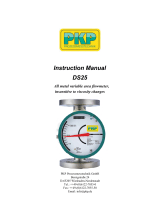
Description:
Model series FK10 conductive level switches are intended
to be used with the FKE electrode relay for detecting the
level of conductive fluids. An A.C. voltage is applied to an
electrode insulated from the tank. When the electrode is
wetted by the process fluid, a low current flows from the
electrode through the fluid to the tank wall (in the case of
plastic tanks, the current flows to a ground electrode). This
current flow is detected by the electrode relay and output
as a switching signal.
Typical Applications:
• To detect the fill limit in tanks containing conductive fluids
• To report whether the tank is empty or full
• To switch over between two filling heights
• To provide overflow protection
• To provide dry-running protection
Benefits:
• No moving parts
• Not influenced by specific gravity of fluid

PKP Process Instruments Inc.
10 Brent Drive · Hudson, MA 01749
SS+1-978-212-0006 · TT+1-978-568-0060
Email: [email protected] · Internet: www.pkp.eu
PKP Prozessmesstechnik GmbH
Borsigstraße 24 · D-65205 Wiesbaden
SS+49 (0) 6122-7055-0 · TT+49 (0) 6122-7055-50
Email: [email protected] · Internet: www.pkp.de
145
Model Coding:
Order Number: FK10.
Conductive Level Switch
Model:
1 = Standard
2 = OEM design
(minimum order: 20 units;
available upon request)
Materials for connector housing /
Process connection:
0 = Delrin (OEM-design only)
1 = Delrin (standard)
2 = Delrin / stainless steel 1.4571
3 = Polypropylene, small
4 = Polypropylene, small /
stainless steel 1.4571
5 = Polypropylene, large
6 = Polypropylene, small /
stainless steel 1.4571
7 = PTFE, small
8 = PTFE, small /
stainless steel 1.4571
9 = PTFE, large
10 = PTFE, large /
stainless steel 1.4571
11 = Stainless steel 1.4571 /
stainless steel 1.457
Process connection:
15 = G1/2 thread (max. 1 electrode)
25 = G1 thread* (max. 3 elctrodes)
32 = G1 1/4 (stainless steel connection
only, max. 4 electrodes)
40 = G1 1/2 thread (max. 5 electrodes)
50 = G2 thread
F50 = DIN DN50 flange
Number of electrodes:
1…5
Electrode material:
1 = Stainless steel 1.4404 (standard)
2 = Hastelloy B (4 mm diameter only)**
3 = Hastelloy C (4 mm diameter only)**
4 = Titanium (4, 8, 10 mm diameters only)**
Electrode diameter:
1 = 4 mm (standard)
2 = 6 mm
3 = 8 mm
4 = 10 mm
Electrode insulation:
1 = Polyamid (standard)
2 = Halar (PTFE)
Electrode length (from edge of seat)
LA = length 500 mm
LB = length 1,000 mm
LS = Special order
Example of ordering notation: L1300 / L2400 / L3500, etc.
* max. two electrodes with stainless steel thread
** with electrode isolation from Halar only
1. 15. 1. 1.
1. 1. 1. LA
Models:
FK10.1: Single/multiple-electrode designs with
mounting thread at plastic housing
Stainless steel housing with plastic or
stainless steel mounting thread
FK10.2: OEM design with plastic (Delrin) housing
as a one- or two-electrode sensor probe,
process connection (1/2“ or 1”), and
stainless steel electrode(s) with perma-
nently attached connection cable
(3 m PUR)
Technical Specifications:
Max. pressure: 10 bar (plastic);
20 bar (stainless steel)
Max. temperature: -20°C…90°C (plastic);
-20°C…100°C (stainless steel)
Protection type: IP65 (FK10.1)
IP68 (FK10.2)
Materials:
Housing: Delrin, polypropylene,
PTFE, stainless steel 1.4571
Process connection: Delrin, polypropylene,
PTFE, stainless steel 1.4571
Sensor stem: Stainless steel 1.4404, Hastelloy
B,Hastelloy C, titanium
Coating: Polyamide, Halar (PTFE)
Dimensions:
FK10.1.1.15.1… (plastic) FK10.1.6 .15.1… (stainless steel)
/