Page is loading ...

PKP Prozessmesstechnik GmbH
Borsigstrasse 24
D-65205 Wiesbaden-Nordenstadt
Tel: 06122 / 7055 - 0
Fax: 06122 / 7055 – 50
Operating Instructions
PDP02
Differential pressure gauge with diaphragm
measuring system and two measuring chambers

INSTRUCTION LEAFLET FOR PRESSURE GAUGES
WARNING:
Incorrect use of pressure gauges can cause damage and injuries. Under this Directive, the user must ensure that pressure gauges are installed
and used in such a way that pressure-related hazards are eliminated to a maximum extent.
Before starting installation, follow the recommendations of standard EN 837-2:
Check that the pressure gauge, designed in compliance with standard EN 837-1/3, is suitable for the planned use in terms of:
▪ Operating pressure (OP) ▪ Type of mounting
▪ Operating temperature (OT) ▪ Compatibility of materials in contact with the fluid to be measured
▪ Safety level of the pressure gauge ▪ Environmental conditions, vibrations, shocks, pulses, ambient atmosphere
▪ Connection interface ▪ Check that the pressure gauge is compatible with the surrounding atmosphere
USE IN AN OXYGEN CIRCUIT
Check that the pressure gauge is designed for such an application. The dial must have the word OXYGEN printed in red and the international
symbol “oil-free” (a crossed-out burette). The pressure gauge must not have been in contact with oil or grease that is incompatible with oxygen:
RISK OF EXPLOSION!
Mounting
A pressure gauge must be mounted in compliance with standard practice.
We advise to mount with an isolation valve.
The user must check that the connections are perfectly sealed by using suitable seals that are compatible with the fluid to be measured.
Use a correctly sized spanner to tighten connections. NEVER TWIST THE CASE IN ORDER TO TIGHTEN CONNECTIONS.
Comply with the instructions given on the device when putting it into service.
For pressure gauges fitted with a rear blow-out disc for protection against overpressure, ensure that there is a gap of at least 10 mm
between the rear panel of the casing and the panel immediately next to it.
Likewise, for this type of rear blow-out disc and a casing filled with damping fluid, do not remove the disc from its location.
Only re-use a pressure gauge if the medium is the same as for its first use.
USE
Warning: The operating conditions must be such that the device can be used safely.
THE PRESSURE GAUGE MUST NOT BE SUBJECTED TO:
Mechanical shocks: if there is a risk install it at a distance with a hose connection.
Vibrations: if there is a risk install it at a distance with a hose connection or use a liquid filled pressure gauge.
Pressure pulses: if there is a risk mount a pulsation damper.
Warning: pressure pulses cause a considerable shortening of the operating life of pressure gauges.
Pressures greater than operating pressures (OP). Otherwise use a pressure relief valve.
Temperatures greater or less than operating temperatures (OT). If there is a risk use a siphon mount or mount with hose connection to
respect the temperature at the pressure gauge.
NOTE:
Failure to observe the conditions above may reduce pressure gauge safety. In such cases contact us.
DISASSEMBLY
During disassembly, check that the pressure gauge is no longer under pressure. As a precaution, disassemble it slowly.
Check that the temperature of the pressure gauge body is not sufficient to cause burning.
Check that residues of the product present in the tube and block of the pressure gauge are not dangerous for the operator and the
environment.
MAINTENANCE
The general safety of a facility often depends on the reliability of indications on the pressure gauges installed in the facility.
Any pressure gauge that seems to be giving false readings must be removed immediately, then tested. If the tests prove it is unreliable, it
must be replaced with a new device.
Periodic verifications should be carried out to check the accuracy of pressure gauges.
Any pressure gauge considered to have been subjected to abnormal conditions of use (e.g. fire, wrong fluid, blows, etc.) must not be used.
MAINTENANCE, VERIFICATION OR RECALIBRATION MUST BE CARRIED OUT BY
PERSONNEL APPROVED BY THE CONSTRUCTOR AND USING SUITABLE EQUIPMENT.
IMPORTANT
The instructions in this leaflet must be strictly followed.
The manufacturer declines all responsibility for any direct or indirect damage to property or persons as well as for the consequence, for
example, of lost production resulting from failure to observe the instructions in this leaflet.

Pressure Measurement and Monitoring
PKP Process Instruments Inc.
10 Brent Drive · Hudson, MA 01749
S +1-978-212-0006 · T +1-978-568-0060
Email: [email protected] · Internet: www.pkp.eu
PKP Prozessmesstechnik GmbH
Borsigstraße 24 · D-65205 Wiesbaden
S +49 (0) 6122-7055-0 · T +49 (0) 6122-7055-50
Email: [email protected] · Internet: www.pkp.de
Differential pressure gauge
with diaphragm sensing system
and two measuring chambers
• Low-costdesign
• Madecompletelyofstainlesssteel,
gaskets of Viton and PTFE
• Availablemeasuringranges:
from 0–0.6 bar to 0–16 bar
• Max.staticpressure:20bar
• Highoverloadprotection:
max.4xmeasuringrangeendvalue
• Housingdiameter:100or160mm
• Designsforalltypesofinstallations
available
PDP02
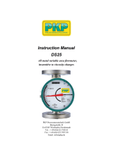
Description:
Model PDP02 differential pressure gauges have two measur-
ing chambers, which are separated by a diaphragm. The dif-
ference in pressure between both chambers causes the dia-
phragm to deflect, the result of which is indicated by the
movement of the needle relative to the gauge scale. These
devices are made completely of stainless steel with gaskets
of Viton and PTFE and available in housing diameters of 100
mm or 160 mm. Housing designs are available for essentially
all possible types of installations.
Typical Applications:
Model PDP02 differential pressure gauges are primarily used
in the following areas of application:
– Filter monitoring
– Petrochemical industry
– Oil and gas systems
– Ship building
– Off-shore facilities
– General industrial applications
– Flow measurement by means of orifice plates or based
on the differential-pressure principle
6/10

PKP Process Instruments Inc.
10 Brent Drive · Hudson, MA 01749
S +1-978-212-0006 · T +1-978-568-0060
Email: [email protected] · Internet: www.pkp.eu
PKP Prozessmesstechnik GmbH
Borsigstraße 24 · D-65205 Wiesbaden
S +49 (0) 6122-7055-0 · T +49 (0) 6122-7055-50
Email: [email protected] · Internet: www.pkp.de
Models:
Nominal size: Housing diameter of 100 or 160 mm
Materials: Housing made of stainless steel 1.4301,
process connection made of stainless steel
1.4571, diaphragm made of Duratherm
Process connection:
2 x G 1/2“ or 2 x 1/2” NPT connections, male
thread; special-order connections optionally
available
Designs:
Version K: for mounting on piping, connection on bottom
Version L: for surface mounting with rim flange on back
side, connection on bottom
Version M: for mounting on piping, connection on back
Version N: for panel mounting, with three-hole bezel, con-
nection on back
Version O: for panel mounting, with three-hole bezel,
connection on bottom
TechnicalSpecifications:
Housing: Round gauge housing made of
stainless steel 1.4301, d = 100 or
160 mm
Pressure-responsive element:
Diaphragm made of Duratherm
(NiCrCo alloy)
Needle movement: Brass, nickel-plated
Glass face: Instrument glass (4 mm)
Scale and needle: Aluminum
Process connection: 1/2" straight thread or NPT (stan-
dard), 1/4", 3/8" straight thread or
NPT (optional), all made of stainless
steel 1.4404. Other connections
available upon request
Gasket: Viton / PTFE
Measuring ranges: See table “Measuring Ranges”
Max. static pressure: See table “Measuring Ranges”
Overload protection: See table “Measuring Ranges”
Media temperature: − 20 °C to +80 °C
Accuracy: Class 2.5
Protection type: IP65
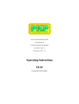
Measuringranges:
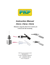
PrincipleofOperation:
1 = Needle movement
2 = Mechanical linkage to measuring element
3 = Diaphragm
ModelCoding:
Order Number: PDP02 10. EV. 15G. 0. K75. 0. 0
Differential pressure gauge
with diaphragm sensor
Models:
10 = Housing diameter of 100 mm
16 = Housing diameter of 160 mm
Materials:
E = Stainless steel, seals Viton / PTFE
S = Special order
Process connection:
15G = 2 x G 1/2 male thread
15N = 2x 1/2" NPT male thread
S = Special-order connection (see table
“Options and Accessories”)
Vibration dampening:
0 = None
Designs and measuring ranges:
K67 to O76 = See table “Measuring Ranges”
Electrical accessories:
0 = None
Options and accessories (more than one may be selected):
0 = None
xxx = See table ”Options and Accessories”
Measuring range
in bar (max. static
pressure, on both
sides) / overload
protection in bar
Designs
Ordering codes
0 … 0.6 (20 / 2.4) K67 L67 M67 N67 O67
0 … 1 (20 / 4) K69 L69 M69 N69 O69
0 … 1.6 (20 / 6.4) K70 L70 M70 N70 O70
0 … 2.5 (20 / 10) K72 L72 M72 N72 O72
0 … 4 (20 / 16) K73 L73 M73 N73 O73
0 … 6 (20 / 20) K74 L74 M74 N74 O74
0 … 10 (20 / 20) K75 L75 M75 N75 O75
0 … 16 (20 / 20) K76 L76 M76 N76 O76

PKP Process Instruments Inc.
10 Brent Drive · Hudson, MA 01749
S +1-978-212-0006 · T +1-978-568-0060
Email: [email protected] · Internet: www.pkp.eu
PKP Prozessmesstechnik GmbH
Borsigstraße 24 · D-65205 Wiesbaden
S +49 (0) 6122-7055-0 · T +49 (0) 6122-7055-50
Email: [email protected] · Internet: www.pkp.de
6/10
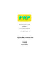
Abmessungen:
PDP02…K
for mounting
on piping,
connection on
bottom
PDP02…L
for surface
mounting with
rim flange on
back side,
connection on
bottom
PDP02…M
for mounting
on piping,
connection
on back
PDP02…N
for panel
mounting, with
three-hole bezel,
connection
on back
PDP02…O
for panel
mounting, with
three-hole bezel,
connection
on bottom
Housing diameter (mm)
100 160
A101.5 162
B80 80
C11 11
E89 119
T20 20
Housing diameter (mm)
100 160
A101.5 162
B80 80
E120 120
T20 20
Housing diameter (mm)
100 160
A101.5 162
B83 83
C14 14
D132 196
E89 119
P116 178
H4.5 6
T20 20
Housing diameter (mm)
100 160
A101.5 162
B80 80
D132 196
E120 120
F3.5 3
G13 15.5
H4.5 6
P116 178
T20 20
Housing diameter (mm)
100 160
A101.5 162
B80 80
C11 11
D132 196
E89 119
F3.5 3
G13 15.5
H4.5 6
P116 178
T20 20

PKP Process Instruments Inc.
10 Brent Drive · Hudson, MA 01749
S +1-978-212-0006 · T +1-978-568-0060
Email: [email protected] · Internet: www.pkp.eu
PKP Prozessmesstechnik GmbH
Borsigstraße 24 · D-65205 Wiesbaden
S +49 (0) 6122-7055-0 · T +49 (0) 6122-7055-50
Email: [email protected] · Internet: www.pkp.de
Description: Code
Scale in psi P
Double scale in bar / psi BP
Special-order scale SK…
Process connection G 1/4 08G
Process connection G 3/8 10G
Process connection 1/4” NPT 08N
Process connection 3/8” NPT 10N
Three-valve manifold made of stainless steel
Process connection: 2 x G 1/4 female thread
Instrument connection: 2 x G 1/2 with rotary
sleeve clamp
3VD-35
The model 3VD-35 valve manifold serves to block off the
connection to the process as well as to provide pressure
compensation between both inlets of the differential pressure
gauge before the actual measurements are taken.
The device is made completely of stainless steel 1.4401.
The fitting packing consists of PTFE.
The valve manifold can be used for all differential pressure
gauges with a minimum distance of 35 mm between the
process connections.
Three-valvemanifoldforPDP02:
Function:
OptionsandAccessories:
/