J COLLECTION DSW3020-MN Installation guide

Type
Installation guide
INSTALLATION
GUIDE
2
TABLE OF CONTENTS
1. SAFETY AND LIABILITY ......................................................................................................................................................... 2
2. TOOLS AND SUPPLIES ......................................................................................................................................................... 3
3. INSTALLATION PROCESS .................................................................................................................................................. 3
3.1 Getting started ................................................................................................................................................ 3
3.2 Fillers ......................................................................................................................................................................... 7
3.3 General installation information ...................................................................................................... 9
3.4 Appliances ............................................................................................................................................................ 9
1. SAFETY AND LIABILITY
The decision has been made to install the cabinets and accessories yourself. This installation
guide is meant to assist you in the general installation process. The installation of cabinetry can
be a challenging task and we do recommend that you use a qualied cabinet installer. However
you may have the skill set to complete the installation on your own. J Collection has no control over
the installation, so you are responsible and liable for completing the installation correctly and safely.
SAFETY AND LIABILITY DISCLAIMER:
Please note that the following instructions are only a guide to cabinet installation.
J Collection will not be liable for any damage to cabinets, cabinet hardware, ooring,
walls, etc., due to improper installation or mishandling of cabinets.
To reduce the risk of serious or fatal injury, read and understand this installation guide
before commencing with the installation.
This J Collection installation guide is not intended to cover every possible contingency
that might be encountered during installation or to endorse the use of any particular tool.
J Collection hereby expressly disclaims all warranties and all liability for any claims
for injury or death related to or based upon the use of this installation guide.
A qualied service professional should be used for any electrical or gas line work.
All gas, electrical and water connections must be shut off in any work area.
ITEMS THAT YOU SHOULD CONSIDER:
Do you have experience with carpentry and cutting miters?
Required tools: for a quality installation you will require several tools. They can be
expensive and require experience to operate in a safe and efcient manner.
Condition of the site: oors are level, and walls are square and level.
Basic plumbing and electrical skills may also be required.
It is recommended that there are two people to install the cabinets.
3
2. TOOLS AND SUPPLIES
The following may or may not be required depending on the complexity of your installation:
UL approved safety goggles, steel-toe shoes and earplugs.
Table saw, miter saw and jig saw.
Drill and bits, compressor, pin nailer and nails.
Clamps, levels, squares, straight edge and line levels.
Extension cord, lighting and ladders.
Stud nder, handle jig and circuit tester.
Tape measure, screwdrivers, hammer pencil and masking tape.
Installation wood screws (1 1/8" and 2 1/2") and screw caps (for wood stud construction).
Carpenter glue.
3. INSTALLATION PROCESS
UNDERSTANDING OUR CABINET CODES - EXAMPLES:
CODE DESCRIPTION
W1830 Wall cabinet 18" wide and 30" high
WA2440 Wall angle corner cabinet 24" wide and 40"
high
B30 Base cabinet, 30" wide and 34 1/2" high
T302484.5 Pantry cabinet, 30" wide, 24" depth and
84 1/2" high
All measurements will be referred to in imperial.
3.1 GETTING STARTED
Check to make sure the cabinets and accessories that you have received are what you
ordered. If anything is not on site, then do not start your project until you have everything
required.
Double-check that you have all the required tools.
Appliances should be moved to another room for easier maneuvering in the work area.
Walls should be nished with the rst coat of paint applied.
4
84 ½" tall cabinet with 30" wall cabinet
94 ½" tall cabinet with 40" wall cabinet
All dimensions are taken with the nished oor installed
It is common that the nished oors are not perfectly level and for that reason all J Collection
cabinets come with legs that are adjustable, making the installation easy and simple to level.
Follow the next steps for the correct installation of your cabinets.
40"
34-1/2"
94-1/2"
54-1
/
2"
34-1/2"
84
-
1/2
"
1) Verify that walls are square and level.
Walls that are not square or level will make
installation more difcult. You can use the
3, 4, 5 method shown to check your corner.
2) Before beginning installation, you must
rst nd the highest point of your oor by
checking it with a level.
5
3) Use a stud nder to mark all the studs
that will be used to install your cabinets.
4) Draw a level line at 34 1/2" from the highest
point of your oor and another level line at
54 1/2" from the same point. Install the top
of the base cabinets level with the 34 1/2"
line by using the adjustable legs to level
the cabinets. Install the bottom of the wall
cabinets level with the 54 1/2" inch line.
5) Starting with the corner wall cabinet,
install (x4) 2 1/2" cabinet screws through
the fastening strips on the cabinet into
the wall studs. Be sure to check for level
before fastening the cabinet into place.
Wall corner
Filler
6) If you do not have a corner, start with
the end closest to a wall, making sure to
leave room for the required ller, as per
your plan.
6
7) Set the next cabinet tight to the rst
cabinet and use clamps to hold in place
while you level it and make sure that
the front edges are ush. Attach the two
cabinets together using 1 1/8" particle
board screws. Attach the cabinet to the
wall with 2 1/2" screws into the studs.
Continue with the same process for all
upper cabinets.
8) Always start with the corner base cabinet
making sure it is level. Install 2 1/2" screws
through the top fastening strip into the
studs that were previously marked.
10) With the base cabinets in place, insert
the toe-kick clips into the leg. Set the
toe-kick in place and push down on the
clip to secure the toe-kick.
9) When installing the base cabinets, start
by unfolding the legs and adjust them
to 4 1/2" from the cabinet base. Place the
cabinet on its legs and put into place.
Further adjustment may be needed to
make the top of the cabinet level with
your 34 1/2" level line.
1
2
3
Push & click
Push down
on clip
7
12)
Set the next cabinet tight to the rst
cabinet and use clamps to hold it place
while you level it and make sure that
the front edges are ush. Attach the two
cabinets together using 1 1/8" particle
board screws. Attach the cabinet to the
wall with 2 1/2" screws into the studs.
Continue with the same process for all
base cabinets.
3.2 FILLERS
A ller is always required against a wall. To cut your ller, measure from the cabinet to the wall
and cut the ller accordingly.
Hold the ller in place; turn it over and on the back side make a pencil mark at the top and
bottom where it should be cut. To prevent chipping when cutting llers, place masking tape over
the surface that is being cut. Join the two marks with a pencil line and saw along that line. Put
the ller in place and drill a pilot hole at hinge-level through the cabinet and into the ller. Attach
the ller to the adjacent cabinet by fastening together with wood screws.
Filler
11) For designs without a corner cabinet,
start with the rst cabinet leaving space
for a ller, as per your plan.
8
When installing a sink or cooktop, trimming the top support
rails may be necessary. Using the template supplied by the
sink or cooktop manufacturer, cut the top rails as required
using a jigsaw.
SINK/COOKTOP INSTALLATION
BASE AND BASE BLIND CORNER CABINETS
BBC (base blind corner) cabinets may be pulled out from the corner if required and the room is
available. When installing a base cabinet at a right angle to a BBC cabinet you must use a ller
to provide clearance for door and drawer handles. The ller width required is usually 1 3/4" - 3"
depending on the type of pull used on the cabinets. Cut the 3" ller to required width. Fasten the
ller to the two adjacent cabinets by drilling through the side of the cabinet into the ller. Screw
together. Ensure cabinets are square in corner and attach the unit to the wall. Make sure all
cabinets are plumb and level. The remaining base cabinets are installed in the same manner.
Using the two C-clamps, align stiles, drill and screw together. Proceed around the room making
sure all cabinets are plumb and level, shimming where necessary, then tighten all screws.
• Minimum 42 3/4"
does not allow
for ller/hardware
clearance.
• Maximum
45 3/4" is with
3" ller attached
to be ush with
the door. Filler not
included.
30"
18"
Filler
Trim this
side of
the ller
to make
it t
#8 x 1 1/2"
screws
Install the remaining base cabinets by aligning the front of the cabinet edges. Clamp the
cabinets together and attach using the 1 1/8" screws. Level the cabinet, adjust as required, and
attach to the wall studs using 2 1/2" screws through the hanging rail located at the top of the
base cabinet. After inserting the screws remove the clamps.
9
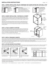
Base Corner Cabinet (BC36LS) - Base corner cabinets are placed squarely in the corner, leveled
and adjusted as required. They are held in place by cabinets on either side. Counter-sink screws on
BC36LS door handles.
Dishwasher Gables - Measure 24 1/8" over from the cabinet at the front and the back and draw a line
on the oor. Draw a plumb line on the wall from the oor to the base cabinet line. These lines
mark the position of the inside of the dishwasher gable. Install a ledger board 24 1/8" long below
the base cabinet guideline. The panel is then installed by attaching it to the ledger strip, oor and
countertop with metal L-brackets.
3.3 General Install Information
The front edge of a fridge gable should be ush with front of the cabinet doors.
Install all cabinets level and plumb.
Install bumpers on all door and drawer fronts, especially corner cabinets.
All cutouts for piping should be as close to pipes as possible with a clean cutout edge.
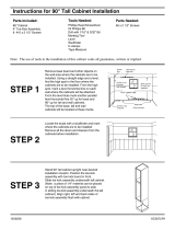
Fridge and Dishwasher Panels/Gables
Fridge panels are fastened to the upper cabinet from the inside of the cabinet. The panel is
to be level and plum with the cabinet. Make sure to add the ller if specied.
Where applicable, raise panels to allow for installation of hardwood ooring (typically
13/16" above sub-oor). Be aware of its construction: 3/4" hardwood, engineered hardwood,
laminate, tile or linoleum ooring have various requirements. The bottom is to be attached to
the nished oor with silicone or an L-bracket.
3.4 Appliances
Today’s appliances are available in all shapes and sizes. Because of this, you must conrm
opening sizes against the spec sheet provided with your paperwork, as well as the manufacturer's
specications.
Standard dishwasher openings are to be 24" wide (unless otherwise specied).
Standard fridge opening is 36" wide x 72" high (unless otherwise specied).
Standard range openings are to be 31 1/4" wide between base cabinets (unless otherwise
specied).
Slide-in ranges – the opening and nished counter height is crucial when dealing with slide-
in ranges. Type of ooring and countertop thickness has to be taken into account. Fillers or
scribe on each side maybe required to make sure drawers and doors clear the range. If base
cabinets are set too low or high the range will not sit ush with the countertop. Countertop
top should be 36" unless otherwise noted.
Note: Never attempt to move an appliance on nished ooring. Do not connect or disconnect any
appliance that is hard-wired or connected to a water source. Always ask for help before attempting
to move an appliance, as appliances are often heavy and there is a high risk of personal injury or
property damage if not properly handled.
  • Page 1 1
  • Page 2 2
  • Page 3 3
  • Page 4 4
  • Page 5 5
  • Page 6 6
  • Page 7 7
  • Page 8 8
  • Page 9 9

J COLLECTION DSW3020-MN Installation guide

Type
Installation guide

Ask a question and I''ll find the answer in the document

Finding information in a document is now easier with AI