Triton Systems 9600 Series Owner's manual

Type
Owner's manual
MEDECO HIGH SECURITY
CUSTOM LOCK INSTALLATION
9100 9600 9700
RL5000 RL2000
RT2000 FT5000 FT5000
XP
ARGO
07103-28209 JUNE 12, 2013
C
ORPORATE HEADQUARTERS:
21405 B Street
Long Beach, MS 39560
Phone: (800) 259 6672
Fax: (228) 868 9445
COPYRIGHT NOTICE
© 2012 Triton. All Rights Reserved. TRITON logo is
a registered trademark of Triton Systems of Delaware.
2
MEDECO HIGH SECURITY LOCK INSTALLATION
PURPOSE
This guide covers the steps for the installation of the high security Medeco key lock. The advantage of the
high security lock is that the key is removable only in the locked position; and its unique design makes
it more tamper proof.
SCOPE
This procedure applies to all VERIFIED TRITON TRAINED service personnel involved in the process
of maintaining or converting Triton ATMs.
APPLICATION
This procedure applies to 9100, 9600, 9700, RL2000, RL5000, RT2000, FT5000, FT5000
XP
& ARGO units.
Note the requirement to reposition the lock’s stop washer in the 9700, RL1600, RL2000, RL5000 & ARGO
fascia installations, (page 6) and spacer washer installation for the 9600 and RL5000 door brackets. (page 7)
REQUIRED PARTS AND TOOLS
TOOLS REQUIRED
Flat tip screwdriver
7/16 inch nutdriver or socket and ratchet
adjustable wrench to take off large nut
Document Updates
August 3, 2012 Original
September 18, 2012 page 7 washer use clari cation
June 12, 2013 Added ARGO
LOCK REMOVAL ...............................................................................................................................pg 3
LOCK INSTALLATION ON ALL CONTROL PANELS ...................................................................pg 4
LOCK INSTALLATION FASCIA 9100 9600 .....................................................................................pg 5
LOCK INSTALLATION FASCIA 9700 RL1600 RL2000 RL5000 ARGO..........................................pg 6
SPACER WASHER INSTALLATION .................................................................................................pg 7
LOCK INSTALLATION RT2000 FT5000 FT5000XP ........................................................................pg 8
3
LOCK REMOVAL ALL LOCKS CONTROL PANEL AND FASCIA
1. Open the control panel or fascia door. Return
the lock to the locked position. Leave the key in
the lock to act as a handle.
2. Remove the 1 (one) bolt holding the latch cam,
and remove the bolt, lock washer and latch cam.
Replace the bolt back on to the lock to retain the
inner tumbler mechanism.
Bolt
Washer
Latch Cam
3. Remove the nut securing the lock, and remove
the lock from the front.
Nut
Removal of the current lock assembly is the same for all cabinets, both the control panel and front fascia
doors. The picture provided is generic to all removals.
4
MEDECO HIGH SECURITY LOCK INSTALLATION
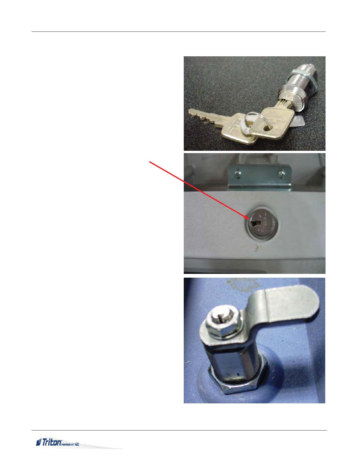
LOCK INSTALLATION ALL CONTROL PANELS
1. Position the lock as shown in the gure to the
right.
Note the “ ats” of the lock body are on the left
and right. The key is in the “locked” position.
Turn key to the right to “unlock”. Return to the
“locked” position. This can be veri ed by remov-
ing the key. Reinsert the key to act as a handle.
2. Remove the large nut, insert the lock into the
control panel opening and reinstall the large nut.
Tighten the nut. Key should be horizontal with
teeth facing to the right.
Representative picture at right.
3. Hold the key, while removing the small nut and
washer from the lock. Do not remove the round
stop washer under the lock washer. With the nut
removed, the inner tumbler mechanism may fall
out if the key is not held rmly.
4. Maintain the hold on the key, install the hasp
onto the end of the lock.
Note the ats on the side of the lock and hasp.
Install the hasp in the vertical “locked” position.
Reinstall the lock washer and nut. Tighten the nut
securely.
Hasp part number:
02113-00008 RL1600 & RL2000
03011-02099 RL5000, 9100/9600/9700
03011-01974 ARGO
Representative lock/hasp installation, 9100
shown in the locked position.
5. Test the movement of the lock before closing
the Control Panel. Ensure the key can be removed
in the closed, locked position only.
5
LOCK INSTALLATION FASCIA PANELS
9100, 9600 Hasp part number 03011-05272
The lock will be installed in the same manner as the Control Panel. Orient the key in the lock horizontally
in the locked position. Below are illustrations of the hasp installed in the locked position. Rotate the key
clockwise to unlock the lock.
9100 9600
Fascia back showing stop washer cam
Fascia back showing hasp and nut/locked
Fascia back showing hasp/locked
6
MEDECO HIGH SECURITY LOCK INSTALLATION
9700, RL1600, RL2000, RL5000, ARGO Hasp part number 03011-02099
1. The lock will be installed in the same manner as the Control Panel. Orient the key in the lock horizon-
tally in the locked position, key on left, teeth facing right.
NOTE: Once the lock body is installed into the door, the stop washer must be repositioned.
2. While holding the key, remove the small nut
and lock washer.
The stop washer should appear as the picture at
the right.
3. Maintain the hold on the key, carefully remove
the stop washer, ip it over, and reinstall. It should
appear as the picture at the right.
4. Maintain the hold on the key, install the hasp
onto the end of the lock.
Note the ats on the side of the lock and hasp.
Install the hasp pointing down. Representative
installation at right showing the locked position.
Install the lock washer and nut, tighten the nut.
5. Test the movement of the lock before closing
the Fascia. The lock rotates to the LEFT to un-
lock. Ensure the key can be removed in the closed,
locked position only.
7
SPACER WASHER INSTALLATION
9600 RL5000
These units may require spacer washers installed behind the cabinet door lock bracket to properly align
the bracket and hasp. Check lock hasp engagement to determine if washers are necessary.
Remove the bolts retaining the bracket and place one washer behind each mounting bolt location. Test the
alignment of the hasp and bracket.
RL5000 9600
8
MEDECO HIGH SECURITY LOCK INSTALLATION
LOCK INSTALLATION RT2000 FT5000 FT5000XP CAM PART NUMBER 03011-01932
1. Open the rear cabinet door. Return the lock to
the locked position, key vertical. Leave the key
in the lock to act as a handle.
2. Remove the 1 (one) bolt holding the latch
cam, and remove the bolt, lock washer and latch
cam. Retain the lock washer.
Bolt
Washer
Latch Cam
3. Remove the nut securing the lock, and remove
the lock from the front.
Nut
4. Position the new lock as shown (locked) and insert into the door. Hold the lock assembly as shown
to ensure the tumbler mechanism does not come out throughout the rest of the installation. Secure the
lock with the nut provided.
9
7. Ensure all hardware is tight. Test the lock
before closing the door. Observe that the key can
only be removed when the door is locked. (Key
horizontal)
6. Install the latch cam, lock washer (retained
from disassembly), and nut.
5. Remove the nut from the end of the lock. En-
sure the lock stop plate stays correctly positioned,
and the tumbler mechanism does not come out
the front.
Cam
Washer
Nut
Lock Stop Plate
  • Page 1 1
  • Page 2 2
  • Page 3 3
  • Page 4 4
  • Page 5 5
  • Page 6 6
  • Page 7 7
  • Page 8 8
  • Page 9 9

Triton Systems 9600 Series Owner's manual

Type
Owner's manual

Ask a question and I''ll find the answer in the document

Finding information in a document is now easier with AI