Page is loading ...

Millerfi
October
1993
Form:
OM-1588
Effective
With
Serial
No.
KD506226
Read
and
follow
these
instructions
and
all
safety
blocks
carefully.
Have
only
trained
and
qualified
persons
install,
operate,
or
service
this
unit.
call
your
distributor
if
you
do
not
understand
the
directions.
OWNERS
MANUAL
DS-64M
(12)
And
(16)
Foot
Boom
Mounted
Wire
Feeder
Boom-Mounted
Microprocessor
Controlled
Constant
Speed
Dual
Wire
Feeder
Multi-Power
Source
Compatible
For
GMAW.
GMAW-P.
And
FCAW
Welding
For
.023
To
1/8
in
(0.6
To
3.2
mm)
Wires
Standard
Wire
Feed
Speed
Of
50
To
780
ipm
(1.3
To
19.8
mpm)
Programmable
Pulse
Weld
Parameters
Circuit
Breaker
Protected
Give
this
manual
to
the
operator.
For
help,
call
your
distributor
or:
MILLER
Electric
Mfg.
Co.,
P.O.
Box
1079,
Appleton,
WI
54912
414-734-9821
cover
7/93
ST-800
172
'
1993
MILLER
Electric
Mig
Cc-
PRINTED
IN
USA

MILLERS
TRUE
BLUETM
LIMITED
WARRANTY
Effective
January
1,
1992
(Equipment
with
a
aerial
number
preface
of
XC
or
newer)
This
limited
werrenty
supersedes
eli
previous
MILLER
werrsntlee
end
is
exclusive
with
no
other
guerentees
or
werrenties
expressed
or
implied.
LIMITED
WARRANTY
Subject
to
the
terms
end
conditions
below,
MILLER
Electric
MIg.
Co..
Appleton,
Wisconsin,
werrents
to
its
original
retell
purcheser
Ihet
new
MILLER
equipment
sold
efter
the
effective
dete
of
this
limited
werrenfy
is
free
of
de
fects
in
materiel
end
workmanship
et
the
time
it
is
shipped
by
MILLER,
THIS
WAR
RANTY
IS
EXPRESSLY
IN
LIEU
OF
ALL
OTHER
WARRANTIES.
EXPRESS
OR
IMPLIED,
INCLUDING
THE
WARRANTIES
OF
MERCHANTABILITY
AND
FIT
NESS.
Within
the
werrenty
periods
listed
below.
MILLER
wilt
repeir
or
reptece
any
war-
rented
perts
or
components
that
fell
due
to
such
detects
in
meteriel
or
worlrnenship.
MILLER
musf
be
notified
in
writing
within
thirty
(30)
deys
of
such
defect
or
failure,
et
which
time
MILLER
will
provide
instructions
on
the
werrenty
cleim
procedures
to
be
followed.
MILLER
shell
honor
werrenty
cleims
on
werrented
equipment
listed
below
in
the
event
of
such
e
feilure
within
the
werrenty
time
periods,
All
werrenty
time
periode
alert
on
the
dete
that
the
equipment
wee
delivered
to
the
origlnel
retelt
purcheser.
or
one
yeer
eher
the
equipment
is
sent
to
the
distributor.
1.
5
Veers
Pens
3
Years
Lebor
Original
mein
power
rectifiers
2.
3
Veers
Perle
end
Lebor
Treneformer/Rectifler
Power
Sources
Plesme
Arc
Cutting
Power
Sources
SemI-Autometic
end
Autometic
Wire
Feeders
Robote
3.
2
Veers
Pens
end
Lebor
Engine
Driven
Welding
Generetore
(NOTE:
Engines
ere
werrented
eeperetely
by
the
engine
menufecturer.)
*
Air
Compressors
4.
1
Veer
Pens
end
Lebor
Motor
Driven
Guns
Process
Controllers
*
Weter
Coolent
Systems
HF
Unite
Grids
Spot
Welders
Loed
Benks
SDX
Trensformers
Running
Geer/Treilere
Field
Options
(NOTE:
Field
options
ere
covered
under
True
Blue
TM
for
the
remelning
werrenty
period
of
the
product
they
ere
instelled
in,
or
for
e
minimum
of
one
yeer
whichever
is
greeter.)
5.
6
Months
Befteries
6.
90
Deys
Pane
end
Lebor
MIG
Gune/TIG
Torches
Plesme
Cutting
Torches
al-
Remote
Controls
Accessory
Kits
Replecement
Pens
MILLERS
True
Blue
TM
Limited
Werrenty
shell
not
epply
to:
1.
Items
furnished
by
MILLER,
but
menufectured
by
others,
such
es
engines
or
trede
ecceesoriee.
These
items
are
covered
by
the
menufecturers
werrenty.
if
eny.
2.
Coneumeble
components:
such
es
contect
tips,
cutting
nozzles.
contectors
end
releys
or
pens
thet
fell
due
to
normel
weer.
3.
Equipment
thet
hes
been
modified
by
eny
petty
other
then
MILLER,
or
equip
ment
thet
hes
been
improperly
instelled,
improperly
opereted
or
misused
beeed
upon
industry
etenderds,
or
equipment
which
he,
not
hed
reesoneble
end
neceseery
maintenance,
or
equipment
which
he,
been
used
tor
operetion
outxide
of
the
specificetione
for
the
equipment.
MILLER
PRODUCTS
ARE
INTENOED
FOR
PURCHASE
AND
USE
BY
COMMER
CIALJINDUSTRIAL
USERS
AND
PERSONS
TRAINED
AND
EXPERIENCED
IN
THE
USE
AND
MAINTENANCE
OF
WELDING
EOUIPMENt
In
the
event
of
e
werrenty
cleim
covered
by
this
werrenty,
the
exclusive
remedies
shell
be,
et
MILLERS
option:
(1)
repeir:
or
(2)
replecement;
or.
where
euthorized
in
writing
by
MILLER
in
eppropriete
cexes.
(3)
the
reesoneble
cod
of
repeir
or
replece
ment
at
en
euthorized
MILLER
service
station;
or
(4)
payment
of
or
credit
for
the
pur
chese
price
(tees
reesonebledeprecietlon
based
upon
ecluel
use)
upon
return
of
the
goods
et
customers
risk
end
expense.
MILLERS
optIon
of
repair
or
replecem,ant
will
be
FOB.,
Fectory
et
Appleton.
Wisconsin.
or
FOB.
etc
MILLER
euthorized
ser
vice
facility
cx
determined
by
MILLER.
Therefore
no
compeneation
or
reimburse
ment
for
transportation
costs
of
any
kind
will
be
allowed.
TO
THE
EXTENT
PERMITTED
BY
LAW,
THE
REMEDIES
PROVIDED
HEREIN
ARE
THE
SOLE
AND
EXCLUSIVE
REMEDtES.
IN
NO
EVENT
SHALL
MILLER
BE
LIABLE
FOR
DIRECt
INDIRECt
SPECIAL,
INCIDENTAL
OR
CONSEOUENTIAL
DAMAGES
(INCLUDING
LOSS
OF
PROFIT),
WHETHER
BASED
ON
CON
TRACT.
TORT
OR
ANY
OTHER
LEGAL
THEORY.
ANY
EXPRESS
WARRANTY
NOT
PROVIDED
HEREIN
AND
ANY
tMPLIED
WAR
RANTY,
GUARANTY
OR
REPRESENTATION
AS
TO
PERFORMANCE.
AND
ANY
REMEDY
FOR
BREACH
OF
CONTRACT
TORT
OR
ANY
OTHER
LEGAL
THEORY
WHICH,
BUT
FOR
THIS
PROVISION,
MIGHT
ARISE
BY
IMPLICATION,
OPERATION
OF
LAW.
CUSTOM
OF
TRADE
OR
COURSE
OF
DEALING,
IN
CLUDING
ANY
IMPLIED
WARRANTY
OF
MERCHANTABILITY
OR
FITNESS
FOR
PARTICULAR
PURPOSE,
WITH
RESPECT
TO
ANY
AND
ALL
EOUIPMENT
FURNISHED
BY
MILLER
IS
EXCLUDED
AND
DISCLAIMED
BY
MILLER.
Some
states
in
the
U.S.A.
do
not
allow
limitations
of
how
long
en
implied
warranty
feats,
or
the
esciuxion
of
incidental,
indirect,
specisl
or
consequential
damages,
so
the
above
limitation
or
exclusion
may
nof
apply
to
you.
This
warranty
provides
spe
cific
legal
rights.
and
other
rights
may
be
available.
but
mey
vary
from
dde
to
state.
In
Canada.
legislation
in
come
provinces
providex
for
certain
additional
warranties
or
remedies
other
then
as
elated
herein,
and
to
the
eetent
that
they
may
not
be
waived,
the
limitations
and
exclusions
set
out
above
may
not
apply.
This
Limited
Warranty
provides
specific
legal
rights.
and
other
rights
may
be
available,
but
may
vary
from
province
to
province.
i-u
j
I
RECEIVING-HANDLING
Before
unpacking
equipment,
check
carton
for
any
damage
that
may
have
occurred
during
shipment.
Fi(e
any
Claims
for
loss
or
damage
with
the
delivering
carrier.
Assistance
for
fi)ing
or
Settling
claims
may
be
obtained
from
distributor
and/or
equipment
manufacturers
Transportation
Department.
When
requesting
information
about
this
equipment,
always
provide
Model
Designation
and
Serial
or
Sty)e
Number.
Use
the
folloWing
spaces
to
record
Model
Designation
and
Serial
or
Style
Number
of
your
unit.
The
information
is
located
on
the
rating
label
or
nameplate.
Model
_________
Serial
or
Style
No.
Date
of
Purchase
miller
5/93a

ERRATA
SHEET
June
2,
1994
FORM:
OM-1
588
-
Use
above
FORM
number
when
ordering
extra
manuals.
After
this
manual
was
printed,
refinements
in
equipment
design
occurred.
This
sheet
lists
exceptions
to
data
appearing
later
in
this
manual.
CHANGES
TO
SECTION
3INSTALLATION
Replace
Section
3-12B.
Welding
Wire
Installation:
Installation
Of
Optional
Wire
Reel
And
Reel
Type
Wire
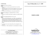
Figure
3-15.
Installation
Of
Optional
Wire
Reel
And
Reel
Type
Wire
CHANGES
TO
SECTION
15
ELECTRICAL
DIAGRAMS
Replace
Figure
15-1.
Circuit
Diagram
For
Wire
Feeder
(see
Pages
2
and
3
on
this
Errata
Sheet)
Replace
Figure
15-2.
Wiring
Diagram
For
Wire
Feeder
(see
Pages
4
and
5
on
this
Errata
Sheet)
1
Retaining
Ring
2
Spanner
Nut
3
Lock
4
Wire
Retainer
5
Wire
Reel
6
Hub
7
Hub
Pin
8
ReelSupport
Remove
retaining
ring.
Pull
lock
and
turn.
Remove
spanner
nut,
wire
retainer,
and
wire
reel
from
hub.
Lay
wire
reel
assembly
on
flat
sur
face,
and
install
wire
as
shown.
Tighten
spanner
nut
until
lock
is
in
position
over
hole
in
wire
retainer.
Pull
lock
and
turn
to
insert
locking
pin
into
wire
retainer.
Slide
wire
reel
assembly
onto
hub,
and
turn
assembly
until
hub
pin
is
seated
in
hole
in
reel.
Reinstall
re
taining
ring.
ST-143
478-A
/
ST-152
463

FRONT
DISPLAY
CM-c
I
09
~
C
LEFT/RIGHT
SELECT
o
o
P825
o
o
P821
LEFT
TRIGGER
o
0
uur~
~-~
1
r
C~ANT
FLOW
5blflQ~
~
P824
d,swxM~uRc
GG
~IXT40I~NT
I
IPI-G8i
(CPTIGHAL)
PLC83
RC23
LEFT
TRIGGER
~T.
PLG23
4
>______~1
I
>
~
14>
4
~fl~D
LED
3
>.IIJ
3
>
)
13>
3
2
LEFT
I
>~
~l
>
,
SIhWP&R)l
~>
SELECT
LED
I-I
P1026
II
---H
~
wr(~5fl
~
1
r
c~ANT
FLOW
SWITD~
d
swn~uPc
~
ukEmo.e4T
I
1P1G8i
(OPTIGHAL)
PLG83j
~I4>--~I4
>
~1W)14
4
~I
~
~)I3>
3
NIT)2>
2
~
l)_____~II
>~.~O~SI6PV5~A)II
PLG29
II
~
L
1L
4IcR~R~ESS~
80650
RCIO/PLGIO
PCI I/PLGI
I
PC
I
2/PLC
12
PC
I
5/PLC
IS
PC
16/PLC
16
PC
I
7/PIG
17
10
TRIGGERDEcRE~NT
I
I
-I
~
NN
~e
a~
(1
(1
~
PLG57/PLG57
C12+04
<2E-~<~
2
TK2
COI44AI~C
I
E-~--<~
~
E~-<
7E-~7
>A~<1i
<
69
~~
<3~I
3
~
~
~I3(
~
RIGHT
~~ir
<I
E_L
<II
~*ii>~LL~<1
8/~*
<I6.E~<6.~-~6>--~<I6(
2<14
E_.L.<4
~
>_L..<I
4(2
GS2~
I
6
<5E~-<5E-~45)--~-(15(
6
L
_)
Figure
15-1.
Circuit
Diagram
For
Wire
Feeder
DSPL2
SIDE
DISPLAY
~I~I!I~I~I:
~
oI~I~I~~kII
-1~
r
-
-
-
~T~&;:
~
-
I
C~iECTIGH
FGG
RE~CTE
PRI)IRAJ4
SELECT
I
(SEE
FIELD
DSTRLtTII)I)
I
I I
I
~I111~twiTtifl
____________
~
________________
__
PARAIETER
PARAŁTER
SELECT
SELECT
PC3O
SELECT
I
IOOTO
6
6 6
6
6
I
~
~
________
i23456~
DATA
CARD
)
~
RCIOO-I>>
___________
PC
100-2
>>
___________
!~i
fl
~flfl
I!
fl ~i
_________
RC6I
~~II
RPS-8
____________
FILTER
BOARD
RCIOO-3))-
D~DCNT
OECRE~NT
~,
C1
I
H
I
PC6O
Ii
RCIOI/PLGIOI
I
vv
__
o o o o
CM
T
I
RC6O/PLG6O
I
RCIoo-5>>-
CJ P1
~
N
0000000
ci
PSIl
P842
~
I
RC6I/DATACAROJI
P843
PB44
~u
P040
1IP1~0cu_liC
I
_~.
__~.
RC4I/PLC4I
~
I
o
o
0
0
~
RC
41
~
Lvvvvv
I
_vvvvvvvvJ
~L
~
I
I
I
I
I
_
I I
___
~I~iII~
I
I~~I
~
___________
~I
~I
~i;
I
~I~IdI~
P~AAAAAA
_______________
w
(a
C)
CM
C)
CM
0
j)~)~C_~~)
~~777
mc
c
~
34
CABLE
_______
PCIO
P1~GE
RC24
RIGHT
TRIGGER
o
0
P823
RC26>>
TRIGGER
PC27>
LED
RIGHT
SELECT
LEO
/7
/8
RC2S-I
Rc25-e
TRIGGER
IICPEINT
PC
11-4
PCI
I-8>>--~
PCI
I-I
>>~~
PCI
I-5>>---~
PCI
I-2>>---~~~
PCI
I-6>>-~
PCI
I_3>>___~I5
PCI
1-7
L
I
P
O.E.I
~TICAL
PC2O
Rc24/P1G24
Rc25-7>
RC2S/P1625
I
CR
01
I
~
XTAD$NT
I
IPTII31
N~
~0
~Ic
P1G57/PLGSI
I
:2~I
2
~I7
~
~
~I7~
~
3~Q,3
I
<-~-<l
iE-~-*I
>2~<
:6
4-~-<6<~~6
>-~-<6~-~-
?
2<14
~
>~<I~
GSIS.
I I
~
<~
S
u~~-.<
5E-~-~5
>~<I
5u(~L
OM-1588
Page
2

~1
R1~CTE
PEI~OAP)T
RPS-8
(OPTION)
RPS-8
SWITcH
BOARD
RD
I
0/PIG
I
10
SHIELD
~RClIO-4
~RCI
10-3
-~RCI
10-I
I
.~RclIo-5
0PDCANT
<<RCIIO-2
I
I
~,
o._.~uo
IJI~
I
5~g/
II
~~RV
It
r
i
14
PIN
PLL~
IOV
Pf~W
I
>c
~3WC
I
P.S.
CO4O~
acw1
>0
__________________________________________________________________
I
L
/0
4
cOIOXTDR
_
C~~
____________
-
Rc55-4
RD55-8
RCS5-l
-
Rc55-5
RD55-2
5C54-
I
17
PC5O
INTERFACE
BOARD
RCGO/PLGSO
RCS
I/Pt.GS
I
RCO2/P1652
RCO3/PLGS3
RDO4/PLGO4
Rc55/PLGSS
:~ce~-u
,1C82-B
9C82-3
PC8O
I
FILTER
BOARD
9C82/P1G82
I
r
~
cO4lR
~aZ~
RC89/PIG7O
I
RC9O/PLG9O
I
I
RC8I-F
)
7
PIN
C~O~
I
~
F
I
RC8I-C
>
cC/Dy
(~24V.CV(
I
~
c
I
RC8I-E>Q.RRENT
FEEDBAD(
(IV,I0OA)IE)–f~L~E
I
RC8I-G>flOXTA~cE
(0-IOV(
Ic>~c
I
RC8I-M
>
VCLTAGE
FEEOBAD(
(tv/by)
IN)~~
N
CQ*ECT
I
TO
POWER
I
I
RC87
45RC70
I
PLO7O
W~
~RD~
SD~DR
r
>
I
H~
i
IDRTIONAL)
I
L
(SEE
FIELD
INSTRLCTI~G)
rUSED
WITH
SWIPGARC
DETA$NT
PTIDR
L
RC9O-
I
>>~~~8~>.<
8
(
>8
~
>...
DRIVE
ASSY
PICK-IP(RIGHT)
RC9O-5
>~B~O(~~
~
PI~-~
(LEFT)
____
~
________
DRIVE
ASSY
SENSE
CLA~#
182-0
RD82-1
1C82-8
III
~
.0 0
~
~
I
~
RC82-6
182-Il
RC9O-2
RC9O-4
RC9O-6
RC9O-3
RC89-
I
>
PfA*~
RC89-2
>>~
RC89-3>>
acw
RC80>HF
STUD
<<RC4-4~
~
RC4-I
0
RcS-3:
RcO-Io:
RCA-6
RC4-9
5Db-I
PC
I
MOTOR BOARD
RC
I/PIG
I
RC2/PLG2
RC3/PIG3
RC4/PLG4
RCS/PLGS
RCG/PLG6
PIG
19
~
>
F
~
)H
P.S.
COATACTOR
.
I
)
B
I
CO*ECT
TO
POWER
24VACCI~O
.EP1
>~
L
SD-164
541-B
OM-1588
Page
3

PC2O
FRONT
DISPLAY
Pc
10
MICROPROCESSOR
RC27
PLG27
efifiuI
690(6C37-7)
430(RC37-e)
6&I(6C37-3)
(RC37-4
I
6 2
IOA~(Rt37-2
6
IIE(RC37-II
-
6F(RC37-5)
1H(RC37-6)
PLG33
RC37
3
20/
~LL
~I~I
~
PLG37
~II
)
LA
C
Figure
15-2.
Wiring
Diagram
For
Wire
Feeder
C
C
a
OM-1588
Page
4

PLG3B
RIGHT
c1P19,
Is
PCI
MOTOR
BOARD
II
PLG2B
LEFT
A
C
U
3
SD-164
540-B
OM-1588
Page
5

CHANGES
TO
SECTION
16
PARTS
LIST
Change
Parts
List
as
follows:
Dia.
Mkgs.
Part
No.
Replaced
With
91-
Added
165798
91-
Added
163282
92-2
164
842
155
024
Description
Quantity
RETAINER,
spool
support
(Eff
w/KE621
826)
(consisting
of)
1
LABEL,
caution
falling
wire
reel
can
cause
damage
1
NUT,
spanner
retaining
(Eff
w/KE621
826)
1
Eff
w/KE593886
PANEL,
front
(Eff
w/KE623992)
1
WASHER,
fIat
.625
ID
nylafil
(Eff
w/KE623992)
...
1
KNOB,
pointer
(Eff
w/KE623992)
1
WASHER,
shldr
.612
ID
(Effw/KE623992)
1
RING,
ring
ext
.625
shaft
grv
x
.045
thk
E
style
(Effw/KE623992)
1
SPRING,
cprsn
.573
OD
x
.088
wire
x
1.062
Ig
(Effw/KE644333)
2
SPACER,
locating
(Eff
w/KE552693)
2
WASHER,
flat
.257
ID
stl
(Eff
w/KE644333)
2
SPRING,
pressure
arm
retaining
LH
(Effw/KE644333)
2
SPRING,
pressure
arm
retaining
RH
(Effw/KE644333)
2
NUT,
.250-28
stl
(Eff
w/KE644333)
2
LENS,
clear
anti
glare
1
**First
digit
represents
page
no
digits
following
dash
represent
item
no.
+When
ordering
a
component
originally
displaying
a
precautionary
label,
the
label
should
also
be
ordered.
BE
SURE
TO
PROVIDE
MODEL
AND
SERIAL
NUMBER
WHEN
ORDERING
REPLACEMENT
PARTS.
83-12
124905
+168
104
83-13
124904
85-24
.
PLG1O3
.
135635
87-2
161714
87-10
157
113
.87-11
097924
87-
Added
87-
Added
166594
168103
Deleted
167697
010291
167700
167633
159264
91-14
133603
165934
91-32
154031
91-
Added
91-
Added
167387
165799
163281
OM-1588
Page
6

ARC
WELDING
SAFETY
PRECAUTIONS
ELECTRIC
SHOCK
can
kill.
Touching
live
electrical
parts
can
cause
fatal
shocks
or
severe
burns.
The
electrode
and
work
circuit
is
electrically
live
whenever
the
output
is
on.
The
input
power
circuit
and
machine
internal
circuits
are
also
live
when
power
is
on.
In
semiautomatic
or
automatic
wire
welding,
the
wire,
wire
reel,
drive
roll
housing,
and
all
metal
parts
touching
the
welding
wire
are
electrically
live.
Incorrectly
installed
or
improperly
grounded
equipment
is
a
hazard.
1.
Do
not
touch
live
electrical
parts.
2.
Wear
dry,
hole-free
insulating
gloves
and
body
protection.
3.
Insulate
yourself
from
work
and
ground
using
dry
insulating
mats
or
covers.
4.
Disconnect
input
power
or
stop
engine
before
installing
or
servicing
this
equipment.
FLYING
SPARKS
AND
HOT
METAL
can
cause
injury.
Chipping
and
grinding
cause
flying
metal.
As
welds
cool,
they
can
throw
oft
slag.
5.
Properly
install
and
ground
this
equipment
according
to
its
Owners
Manual
and
national,
state,
and
local
codes.
6.
When
making
input
connections,
attach
proper
grounding
conductor
first.
7.
Turn
off
all
equipment
when
not
in
use.
8.
Do
not
use
worn,
damaged,
undersized,
or
poorly
spliced
cables.
9.
Do
not
wrap
cables
around
your
body.
10.
Ground
the
workpiece
to
a
good
electrical
(earth)
ground.
11.
Do
not
touch
electrode
if
in
contact
with
the
work
or
ground.
12.
Use
only
well-maintained
equipment.
Repair
or
replace
damaged
parts
at
once.
13.
Wear
a
safety
harness
if
working
above
floor
level.
14.
Keep
all
panels
and
covers
securely
in
place.
1.
Wear
approved
face
shield
or
safety
goggles.
Side
shields
recommended.
2.
Wear
proper
body
protection
to
protect
skin.
a
WARNING
ARC
WELDING
can
be
hazardous.
PROTECT
YOURSELF
AND
OTHERS
FROM
POSSIBLE
SERIOUS
INJURY
OR
DEATH.
KEEP
CHILDREN
AWAY.
PACEMAKER
WEARERS
KEEP
AWAY
UNTIL
CONSULTING
YOUR
DOCTOR.
In
welding,
as
in
most
jobs,
exposure
to
certain
hazards
occurs.
Welding
is
safe
when
precautions
are
taken.
The
safety
information
given
below
is
only
a
summary
of
the
more
complete
safety
information
that
will
be
found
in
the
Safety
Standards
listed
on
the
next
page.
Read
and
follow
all
Safety
Standards.
HAVE
ALL
INSTALLATION,
OPERATION,
MAINTENANCE,
AND
REPAIR
WORK
PERFORMED
ONLY
BY
QUALIFIED
PEOPLE.
ARC
RAYS
can
burn
eyes
and
skin;
~I
NOISE
can
damage
hearing.
Arc
rays
from
the
welding
process
produce
intense
heat
and
strong
ultraviolet
rays
that
can
burn
eyes
and
skin.
Noise
from
some
processes
can
damage
hearing.
NOISE
1.
Use
approved
ear
plugs
or
ear
muffs
if
noise
level
is
high.
ARC
RAYS
2.
Wear
a
welding
helmet
fitted
with
a
proper
shade
of
filter
(see
ANSI
Z49.
1
listed
in
Safety
Standards)
to
protect
your
face
and
eyes
when
welding
or
watching.
3.
Wear
approved
safety
glasses.
Side
shields
recommended.
4.
Use
protective
screens
or
barriers
to
protect
others
from
flash
and
glare;
warn
others
not
to
watch
the
arc.
5.
Wear
protective
clothing
made
from
durable,
flame-resiŒtant
material
(wool
and
leather)
and
foot
protection.
FUMES
AND
GASES
can
be
hazardous
5.
Work
in
a
confined
space
only
if
it
is
well
ventilated,
or
while
to
your
health.
wearing
an
air-supplied
respirator.
Shielding
gases
used
for
Welding
produces
fumes
and
gases.
Breathing
these
fumes
and
gases
can
be
hazardous
to
your
health.
welding
can
displace
air
causing
injury
or
death.
Be
sure
the
breathing
air
is
safe.
1.
2.
Keep
your
head
out
of
the
fumes.
Do
not
breathe
the
fumes,
.
If
inside,
ventilate
the
area
and/or
use
exhaust
at
the
arc
to
6.
Do
not
weld
in
locations
near
degreasing,
cleaning,
or
spraying
operations.
The
heat
and
rays
of
the
arc
can
react
with
vapors
to
form
highly
toxic
and
irritating
gases.
remove
welding
fumes
and
gases.
7.
Do
not
weld
on
coated
metals,
such
.as
galvanized,
lead,
or
3.
If
ventilation
is
poor,
use
an
approved
air-supplied
respirator.
cadmium
plated
steel,
unless
the
coating
is
removed
from
the
4.
Read
the
Material
Safety
Data
Sheets
(MSDSs)
and
the
weld
area,
the
area
is
well
ventilated,
and
if
necessary,
while
manufacturers
instruction
for
metals,
consumables,
coatings,
wearing
an
air-supplied
respirator.
The
coatings
and
any
metals
and
cleaners,
containing
these
elements
can
give
oft
toxic
fumes
if
welded.
WELDING
can
cause
fire
or
explosion.
5.
Watch
for
fire,
and
keep
a
fire
extinguisher
nearby.
Sparks
and
spatter
fly
off
from
the
welding
arc.
The
flying
sparks
and
hot
metal,
weld
spatter,
hot
6.
Be
aware
that
welding
on
a
ceiling,
floor,
bulkhead,
or
partition
can
cause
fire
on
the
hidden
side.
workpiece.
and
hot
equipment
can
cause
fires
and
burns.Accidentalcontactofelectrodeorweldingwire
7.
.
Do
not
weld
on
closed
containers
such
as
tanks
or
drums.
to
metal
objects
can
cause
sparks,
overheating,
or
fire.
8.
Connect
work
cable
to
the
work
as
close
to
the
welding
area as
practical
to
prevent
welding
current
from
traveling
long,
possibly
.
1.
Protect
yourself
and
others
from
flying
sparks
and
hot
metal.
2.
Do
not
weld
where
flying
sparks
can
strike
flammable
material.
9.
unknown
paths
and
causing
electric
shock
and
fire
hazards.
.
Do
not
use
welder
to
thaw
frozen
pipes.
3.
Remove
all
flammables
within
35
ft
(10.7
m)
of
thewelding
arc.
If
10.
Remove
stick
electrode
from
holder
or
cut
off
welding
wire
at
this
is
not
possible,
tightly
cover
them
with
approved
covers,
contact
tip
when
not
in
use.
4.
Be
alert
that
welding
sparks
and
hot
materials
from
welding
can
11.
Wear
oil-free
protective
garments
such
as
leather
gloves,
heavy
easily
go
through
small
cracks
and
openings
to
adjacent
areas.
shirt,
cuffless
trousers,
high
shoes,
and
a
cap.
Sri
9/92

CYLINDERS
can
explode
if
damaged.
Shielding
gas
cylinders
contain
gas
under
high
pressure.
If
damaged,
a
cylinder
can
explode.
Since
gas
cylinders
are
normally
part
of
the
welding
process,
be
sure
to
treat
them
carefully.
1.
Protect
compressed
gas
cylinders
from
excessive
heat,
mechanical
shocks,
and
arcs.
2.
Install
and
secure
cylinders
in
an
upright
position
by
chaining
them
to
a
stationary
support
or
equipment
cylinder
rack
to
prevent
falling
or
tipping.
3.
Keep
cylinders
away
from
any
welding
or
other
electrical
circuits.
4.
Never
allow
a
welding
electrode
to
touch
any
cylinder.
5.
Use
only
correct
shielding
gas
cylinders,
regulators,
hoses,
and
fittings
designed
for
the
specific
application;
maintain
them
and
associated
parts
in
good
condition.
6.
Turn
face
away
from
valve
outlet
when
opening
cylinder
valve.
7.
Keep
protective
cap
in
place
over
valve
except
when
cylinder
is
in
use
or
connected
for
use.
8.
Read
and
follow
instructions
on
compressed
gas
cylinders,
associated
equipment,
and
CGA
publication
P-i
listed
in
Safety
Standards.
ENGINE
EXHAUST
GASES
can
kill.
1.
Use
equipment
outside
in
open,
well-ventilated
areas.
2.
If
used
in
a
closed
area,
vent
engine
exhaust
outside
and
Engines
produce
harmful
exhaust
gases.
away
from
any
building
air
intakes.
ENGINE
FUEL
can
cause
fire
or
1.
Stopenginebeforecheckingoraddingfuel.
explosion.
2.
Do
not
add
fuel
while
smoking
or
if
unit
is
near
any
sparks
or
open
flames.
3.
Allow
engine
to
cool
before
fueling.
If
possible,
check
and
add
Engine
fuel
is
highly
flammable.
fuel
to
cold
engine
before
beginning
job.
4.
Do
not
overfill
tank
allow
room
for
fuel
to
expand.
5.
Do
not
spill
fuel.
If
fuel
is
spilled,
clean
up
before
starting
engine.
MOVING
PARTS
can
cause
injury.
3.
Have
only
qualified
people
remove
guards
or
covers
for
maintenance
and
troubleshooting
as
necessary.
Moving
parts,
such
as
fans,
rotors,
and
belts
can
cut
fingers
and
hands
and
catch
loose
clothing.
SPARKS
can
cause
BATTERY
GASES
TO
EXPLODE;
BATTERY
ACID
can
burn
eyes
and
skin.
Do
not
allow
tools
to
cause
sparks
when
working
on
a
battery.
Do
not
use
welder
to
charge
batteries
or
jump
start
vehicles.
Observe
correct
polarity
(+
and
)
on
batteries.
ir~
~
.
.~
/
STEAM
AND
COOLANT
can
skin.
The
coolant
in
the
r
under
pressure.
PRESSURIZED
HOT
burn
face,
eyes,
and
adiator
can
be
very
hot
and
1.
2.
3.
Donotremoveradiatorcapwhenengineishot.Allowengine
to
cool.
Wear
gloves
and
put
a
rag
over
cap
area
when
removing
cap.
Allow
pressure
to
escape
before
completely
removing
cap.
PRINCIPAL
SAFETY
STANDARDS
Safety
in
Welding
and
Cutting,
ANSI
Standard
Z49.1,
from
American
Welding
Society,
550
N.W.
LeJeune
Rd,
Miami
FL 33126
Safety
and
Health
Standards,
OSHA
29
CFR
1910,
from
Superinten
dent
of
Documents,
U.S.
Government
Printing
Office,
Washington,
D.C.
20402.
Recommended
Safe
Practices
for
the
Preparation
for
Welding
and
Cutting
of
Containers
That
Have
Held
Hazardous
Substances,
Ameri
can
Welding
Society
Standard
AWS
F4.i
from
American
Welding
So
ciety,
550
N.W.
LeJeune
Rd.
Miami,
FL
33126
National
Electrical
Code,
NFPA
Standard
70,
from
National
Fire
Pro
tection
Association,
Batterymarch
Park,
Quincy,
MA
02269.
Safe
Handling
of
Compressed
Gases
in
Cylinders,
CGA
Pamphlet
P-i,
from
Compressed
Gas
Association,
1235
Jefferson
Davis
High
way,
Suite
501,
Arlington,
VA
22202.
Code
for
Safety
in
Welding
and
Cutting,
CSA
Standard
Wi
17.2,
from
Canadian
Standards
Association,
Standards
Sales,
178
Rexdale
Bou
levard,
Rexdale,
Ontario,
Canada
M9W
I
R3.
Safe
Practices
For
OccupafionAnd
EducationalEyc
And
Face
Protec
tion,
ANSI
Standard
Z87.1,
from
American
National
Standards
Institute,
1430
Broadway,
New
York,
NY
10018.
Cutting
And
Welding
Processes,
NFPA
Standard
518,
from
National
Fire
Protection
Association,
Batterymarch
Park,
Quincy,
MA
02269.
a
WARNING
ENGINES
can
be
hazardous.
I.
Keep
all
doors,
panels,
covers,
and
guards
closed
and
securely
in
place.
2.
Stoc
enaine
before
installing
or
connecting
unit.
4.
To
prevent
accidental
starting
during
servicing,
disconnect
negative
()
battery
cable
from
battery.
5.
Keep
hands,
hair,
loose
clothing,
and
tools
away
from
moving
parts.
6.
Reinstall
panels
or
guards
and
close
doors
when
servicing
is
finished
and
before
starting
engine.
Batteries
contain
acid
and
generate
explosive
gases.
1.
2.
3.
4.
5.
Always
wear
a
face
shield
when
working
on
a
battery.
Stop
engine
before
disconnecting
or
connecting
battery
cables.
srI
9/92

PRECAUTIONS
DE
SECURITE
EN
SOUDAGE
A
LARC
DESSAI.
LELECTROCUTION
peut
Œtre
mortelle.
Une
decharge
electrique
peut
vous
tuer
ou
vous
briDler
gravement.
LØlectrode
et
le
circuit
de
soudage
sont
sous
tension
au
dØmarrage.
Le
circuit
dentrØe
et
les
circuits
internes
des
matØriels
sont
aussi
sous
tension
des
Ia
mise
en
marche.
En
soudage
automatique
ou
semi-automatique
avec
fil,
ce
dernier,
le
support
de
roquette,
le
logement
des
galets
dentraInement
et
toutes
les
piŁces
metalliques
en
contact
avec
le
tilde
soudage
sont
sous
tension.
Des
matØriels
mal
installØs
ou
mal
mis
a
Ia
terre
sont
dangereux.
1.
Ne
touchez
pas
a
des
piŁces
sous
tension.
2.
Portez
des
gants
et
des
vØtements
isolants,
secs
et
non
trouŁs.
3.
lsolez-vous
de
Ia
tle
a
souder
et
de
Ia
mise
ala
terre
au
moyen
de
petits
tapis
isolants
ou
autres.
4.
DØconnectez
Ia
prise
dentrØe
des
matØriels
ou
arrŒtez
leur
moteur
avant
de
les
installer
ou
den
faire
Ientretien.
LE
SOUDAGE
A
LARC
est
dangereux.
5.
Veillez
a
installer
ces
matØriels
eta
es
mettre
ala
terre
selon
le
manuel
dutilisation
et
es
codes
nationaux,
provinciaux
et
locaux
applicables.
6.
ArrŒtez
tous
les
matØriels
aprŁs
utilisation.
7.
Nutilisez
pas
de
cables
uses,
endommagØs,
mat
ØpissØs
ou
de
calibre
trop
petits.
8.
Nenroulez
pas
de
cables
autour
de
votre
corps.
9.
Mettez
ala
terre
Ia
tote
a
souder
au
moyen
dune
bonne
prise
de
terre.
10.
Ne
touchez
pas
a
lØlectrode
si
vous
Œtes
en
contact
avec
le
circuit
de
soudage
(terre).
11.
Nutilisez
que
des
matØriels
en
bon
Øtat.
ROparez
ou
remplacez
sur-le-champ
les
piŁces
endommagØes.
12.
Portez
un
harnais
de
sØcuritØ
Si
vous
travaillez
en
hauteur.
13.
Fermez
solidement
tous
es
panneaux
et
les
capots.
Le
RAYONNEMENT
DE
LARC
peut
brUler
les
yeux
et
Ia
peau;
le
BRUIT
peut
endommager
IouIe.
Larc
de
soudage
produit
une
chaleur
et
des
rayons
ultraviolets
intenses,
susceptibles
de
brler
les
yeux
et
a
peau.
Le
bruit
cause
par
certains
procØdØs
peut
endommager
louIe.
1.
Portez
un
casque
de
soudeur
avec
Øcran
filtrant
de
teinte
appropriee
(consultez
Ia
norme
ANSI
Z49
indiquØe
ci-apres),
pour
vous
proteger
le
visage
et
les
yeux
lorsque
vous
soudez
ou
I
Les
VAPEURS
ET
LES
FUMEES
sont
dangereuses
pour
Ia
sante.
I!
Le
soudage
dØgage
des
vapeurs
et
des
fumØes
quil
est
dangereux
de
respirer.
1.
Ecartez
le
visage
pour
Øviter
de
respirer
les
fumØes.
2.
A
lintØrieur,
assurez-vous
que
laire
de
soudage
est
bien
ventilØe
ou
que
les
fumØes
et
es
vapeurs
sont
aspirØes
a
arc.
3.
Si
Ia
ventilation
est
mauvaise,
portez
un
respirateur
a
adduction
dair
approuve.
4.
Lisez
es
fiches
signalØtiques
et
les
consignes
du
fabricant
relatives
aux
mØtaux,
aux
produits
consummables,
aux
revŒtements
et
aux
produits
nettoyants.
Le
SOUDAGE
peut
causer
un
incendie
ou
une
explosion.
Larc
produit
des
Øtincelles
et
des
projections.
Avec
Ia
chaleur
intense
degagee
par
Ia
tote
et
es
matØriels,
elles
peuvent
causer
un
incendie
et
des
brlures.
Le
contact
accidentel
de
IØlectrode
avec
un
objet
metallique
peut
provoquer
des
Øtincelles,
un
Øchauffement
ou
un
incendie.
1.
ProtØgez-vous,
ainsi
que
es
autres,
contre
es
Øtincelles
et
les
projections.
2.
Ne
soudez
pas
dans
un
endroit
oiD
des
Øtincelles
peuvent
atteindre
des
matØriaux
inflammables.
3.
Enlevez
toutes
les
matiŁres
intlammables
dans
un
rayon
de
10,7
metres
autour
de
Iarc,
ou
couvrez-les
soigneusement
avec
des
bches
approuvØes.
4.
MØfiez-vous
des
Øtincelles
et
des
Øclats
brCilants,
susceptibles
de
pØnØtrer
dans
des
aires
adjacentes
par
de
petites
ouvertures
ou
fissures.
que
vous
observez
IexØcution
dune
soudure.
-
2.
Portezdes
lunettes
de
sØcuritØ
approuvØes.
Des
Øcrans
latØraux
sont
recommandØes.
3.
Entourez
Iaire
de
soudage
de
rideaux
ou
de
cloisons
de
protection
contre
es
coups
darc
ou
IØblouissement;
avertissez
es
observateurs
de
ne
pas
regarder
arc.
4.
Portez
des
vØtements
en
tissus
ignifuge
durable
(lame
et
cuir)
et
des
chaussures
de
sØcuritØ.
5.
Portez
un
casque
antibruit
ou
des
bouchons
doreille
approuvØs
site
niveau
de
bruit
est
ØlevØ.
5.
Ne
travaillez
dans
un
espace
confine
que
sit
est
bien
ventilØ;
sinon,
portez
un
reSpirateur
adduction
dair.
Les
gaz
protecteurs
de
soudage
peuvent
dØplacer
loxygŁne
de
lair
et
causer
des
blessures
ou
Ia
mort.
Assurez-vous
que
air
est
propre
a
Ia
respiration.
6.
Ne
soudez
pas
a
proximitØ
dopØrations
de
dØgraissage,
de
nettoyage
ou
de
pulvØrisation.
La
chaleur
et
les
rayons
de
Iarc
peuvent
reagir
avec
des
vapeurs
et
former
des
gaz
hautement
toxiques
et
irritants.
7.
Ne
soudez
pas
de
tOles
galvanisØes
ou
plaquees
en
p10mb
ou
en
cadmium
sans
es
avoir
grattees
a
fond,
car
ces
mØtaux,
et
tout
revØtement
qui
en
contient,
peuvent
alors
dØgager
des
fumØes
toxiques.
Assurez-vous
dune
bonne
ventilation
et
portez
un
respirateur
a
adduction
dair
si
cest
nØcessaire.
5.
Mefiez-vous
des
incendies
et
gardez
un
extincteur
a
portee
de
Ia
main.
6.
Noubliez
pas
quune
soudure
sur
un
plafond,
un
plancher,
une
cloison
ou
une
paroi
peut
en
enflammer
Iautre
ctØ.
7.
Ne
soudez
pas
un
recipient
termØ,
comme
un
reservoir
ou
un
tonneau.
8.
Connectez
le
cable
de
soudage
le
plus
pres
possible
de
Ia
tote
de
soudage
pour
empOcher
le
courant
de
suivre
un
parcours
long
et
inconnu,
et
prØvenir
ainsi
tes
risques
dOlectrocution
et
dincendie.
9.
Ne
faites
pas
degeler
des
tuyaux
avec
un
chalumeau.
10.
Videz
votre
carquois
porte-electrodes
ou
coupez
le
fit
au
tube-
contact
aprŁs
le
soudage.
11.
Portez
des
vOtements
protecteurs
non
huileux,
tels
des
gants
en
cuir,
une
chemise
Øpaisse,
un
pantalor,
sans
revers,
des
chaussures
montantes
et
un
casque.
MISE
EN
GARDE
PROTEGEZ-VOUS,
AINSI
QUE
LES
AUTRES,
CONTRE
LES
BLESSURES
GRAVES
POSSIBLES
OU
LA
MORT.
NE
LAISSEZ
PAS
LES
ENFANTS
SAPPROCHER,
NI
LES
PORTEURS
DE
STIMULATEUR
CARDIAQUE
(A
MOINS
QUILS
NAIENT
C0NSL,LTE
UN
MEDECIN).
Le
soudage,
comme
Ia
plupart
des
activitØs
industrielles,
expose
a
certains
risques.
Le
soudage
nest
pas
dangereux
lorsquon
prend
des
precautions.
Les
consignes
di~ØcuritØ
suivantes
ne
font
que
rØsumer
linformation
contenue
dans
les
normes
ØnumØrØes
ci-aprŁs.
Lisez
et
respectez
toutes
ces
normes.
SEULES
DES
PERSONNES
OUALIFIEES
DOIVENT
FAIRE
DES
TRAVAUX
DINSTALLATION,
DE
REPARATION,
DENTRETIEN
ET
=~

Les
BOUTEILLES
endommagØes
peuvent
exploser.
Les
bouteilles
contiennent
des
gaz
protecteurs
sous
haute
pression.
DesbouteillesendommagŁespeuvent
exploser.
Comme
les
bouteilles
font
normalement
partie
du
procede
de
soudage,
traitez-les
avec
soin.
1.
Les
bouteilles
doivent
Œtre
protegees
contre
les
sources
de
chaleur
intense,
les
chocs
et
les
arcs
de
soudage.
2.
EnchaInez
verticalement
es
bouteilles
a
un
support
ou
a
un
cadre
fixe
pour
es
empŒcher
de
tomber
ou
dŒtre
renversØes.
3.
Eioignez
les
bouteilles
de
tout
circuit
Ølectrique
ou
de
soudage.
4.
EmpŒchez
tout
contact
entre
une
bouteille
et
une
electrode.
5.
Nutilisez
que
des
bouteilles
de
gaz
protecteur,
des
dØtendeurs,
des
flexibles
et
des
raccords
concus
pour
chaque
application
spØcifique;
ces
matØriels
et
les
piŁces
connexes
doivent
Œtre
en
bon
etat.
6.
Ne
mettez
pas
le
visage
devant
le
robinet
de
bouteille
en
louvrant.
7.
Remettez
le
chapeau
de
bouteille
aprŁs
utilisation.
8.
Lisez
et
respectez
los
consignes
relatives
aux
bouteilles
de
gaz
comprimØ
et
aux
matØriels
connexes,
ainsi
que
Ia
publication
P-i
de
Ia
CGA,
ŁnumØrees
dans
les
normes
ci-dessous.
Les
GAZ
DECHAPPEMENT
DES
MOTEURS
PEU
VENT
ETRE
MORTELS.
Les
moteurs
produisent
des
gaz
dØchappement
nocifs.
Le
CARBURANT
peut
causer
un
incendie
ou
une
explosion.
Le
carburant
est
hautement
inflammable.
1.
ArrŒtez
le
moteur
avant
de
verifier
le
niveau
de
carburant
ou
de
faire
le
plein.
2.
Ne
faites
pas
le
plein
en
fumant
.ou
proche
dune
source
Des
PIECES
EN
MOUVEMENT
peuvent
causer
des
blessures.
Des
piŁces
en
mouvement,
telles
des
ventilateurs,
des
rotors
et
des
courroies
peuvent
couper
les
doigts
et
es
mains,
ou
accrocher
des
vŁtements
amples.
1.
Assurez-vous
que
les
portes,
les
panneaux,
les
capots
et
les
protecteurs
sont
bien
fermŁs.
2.
Avant
dinstaller
ou
de
connecter
un
systeme,
arrŒtez-en
le
moteur.
3.
Seules
des
personnes
qualifiees
doivent
dØmonter
des
Des
ETINCELLES
peuvent
FAIRE
EXPLOSER
UN
ACCUMULATEUR;
LELECTROLYTE
DUN
ACCUMULATEUR
peut
brUler
Ia
peau
et
les
yeux.
Les
accumulateurs
contiennent
de
lelectrolyte
et
degagent
des
vapeurs
explosives.
1.
Portez
toujoUrs
un
Øcran
facial
en
travaillant
sur
Safety
in
Welding
and
Cutting
norme
ANSI
Z49.
1,
American
Welding
Society,
550,
N.W.
LeJeune
Rd.,
Miami
FL
33128.
Safety
and
Health
Standards
OSHA
29
CFR
1910,
Superintendent
of
Documents,
U.S.
Government
Printing
Office,
Washington
D.C.
20402.
Recommended
Safe
Practices
For
the
Preoaration
For
Welding
and
Cutting
of
Containers
That
Have
Held
Hazardous
Substances
norme
AWS
F4.1,
American
Welding
Society,
550.
NW.
LeJeune
Rd.,
Miami
FL
33128.
Les
MOTEURS
peuvent
Œtre
dangereux.
1.
Utilisez
des
machines
a
lextØrieur
dans
des
aires
ouvertes
et
bien
ventilØes.
2.
Si
vous
utilisez
des
machines
dans
un.
endroit
confine,
les
fumØes
dØchappement
doivent
Œtre
envoyØes
a
lextØrieur,
loin
des
prises
dair
du
btiment.
dØtincelles
ou
dune
flamme
nue.
3.
Si
cest
possible,
laissez
le
moteur
refroidir
avant
de
faire
le
plein
de
carburant
Cu
den
verifier
le
niveau
au
debut
du
soudage.
4.
Ne
faites
pas
le
plein
de
carburant
a
ras
bord
:~prevoyez
de
lespace
pour
son
expansion.
5.
Faites
attention
de
ne
pas
renverserde
carburant.
NettOyez
tout
carburant
renversØ
avant
de
faire
dØmarrer
le
moteur.
protecteurs
ou
des
capots
pourfaire
lentretien
ou
le
depannage
nØcessaire.
4.
Pour
empecher
un
demarrage
accidentel
dun
systŁme
pendant
lentretien,
dŁbranchez
le
cable
daccumulateur
a
Ia
borne
negative.
5.
Napprochez
pas
les
mains
ou
les
cheveux
do
piŁces
en
mouvement;
elles
peuvent
aussi
accrocher
des
vØtements
amples
et
des
outils.
6.
RŁinstallez
les
capots
ou
es
protecteurs
et
fermez
les
portes
aprŁs
des
travaux
dentretien
et
avant
de
faire
dØmarrer
le
moteur.
un
accumulateur.
2.
ArrŒtez
le
moteur
avant
de
connecter
ou
de
dŁconnecter
des
cables
daccumulateur.
3.
Nutilisez
que
des
outils
anti-Øtincelles
pour
travailler
sur
un
accumulateur.
4.
Nutilisez
pas
un
paste
de
soudage
pourchargerun
accumulateur
Cu
connecter
provisoirement
un
vØhicule.
Utilisez
Ia
polarite
correcte
(+
et
-)
de
laccumulateur.
Safe
Handling
of
Compressed
Gases
in
Cylinders
document
P-i,
Compressed
Gas
Association,
1235
Jefferson
Davis
Highway,
Suite
501,
Arlington,
Va
22202.
Code
for
Safety
in
Weldina
and
Cutting
norme
CSA
Wi
17.2,
Asso
ciation
canadienne
de
normalisation,
Standards
Sales,
176
Rexdale
Boulevard,
Rexdale,
Ontario,
Canada
M9W
1
R3.
Safe
Practices
for
Occupation
and
Educational
Eve
and
Face
Protec
Ii~n,
norme
ANSI
Z87.
1
,American
National
Standards
Institute,
1430
Broadway,
New
York,
NY
10018.
5.
National
Electrical
Code
norme
70
NFPA,
National
Fire
Protection
Association,
Batterymarch
Park,
Quincy,
MA
02269.
srlf
9/91
Cutting
and
Welding
Processes
norme
51B
NFPA,
National
Fire
Protection
Association,
Batterymarch
Park,
Quincy,
MA
02269.
LES
ETINCELLES
ET
LES
metaL
En
refroidissant,
Pa
soudure
peut
projeter
du
laitier.
PROJECTIONS
BRULANTES
peuvent
causer
des
blessures.
Le
piquage
et
le
meulage
produisent
des
Øclats
de
1.
2.
Portez
un
Øcran
facial
ou
des
lunettes
a
coques
approuvees.
Des
Øcrans
latØraux
sont
recommandØs.
Portez
des
vŒtements
de
protection
individuelle
appropriØs.
MISE
EN
GARDE
La
VAPEUR
ET
LE
LIQUIDE
DE
1.
Ntez
pas
le
bouchon
de
radiateur
tant
que
le
moteur
na
pas
REFROIDISSEMENT
BRULANT
SOUS
PRESSION
peuvent
brler
Ia
peau
et
les
eux
Le
liquide
de
refroidissement
dun
radiateur
peut
etre
2.
3.
refroidi.
Mettez
des
gants
et
posez
un
torchon
sur
le
bouchon
pour
lter.
Laissez
Pa
pression
sØchapper
avant
dter
completement
le
bouchon.
brlant
et
sous
pression.
PRINCIPALES
NORMES
DE
SECURITE

EMF
INFORMATION
TABLE
OF
CONTENTS
SECTION
1
SAFETY
IN
FORMATION
SECTION
2
SPECIFICATIONS
3INSTALLATION
Equipment
Connection
Diagram
Installing
Swivel
Into
Pipe
Post
Installing
Control
Box
Onto
Swivel
Installing
Boom
And
Reel
Support
Installing
Wire
Guide
Extension
Wire
Guide
And
Drive
Roll
Installation
Welding
Gun
Connections
Wire
Feed
Motor
And
Gas
Valve
Control
Connections
Control
Connection
Shielding
Gas
And
Weld
Cable
Connections
Removing
Safety
Collar
And
Adjusting
Boom
Welding
Wire
Installation
Motor
Start
Control
Threading
Welding
Wire
SECTION
4GLOSSARY
14
SECTION
5
OPERATION
5-1.
Front
Panel
Controls
5-2.
Side
Panel
Controls
5-3.
Rear
Panel
Controls
5-4.
Setting
Switches
On
450
Ampere
lnverter
Model
Welding
Power
Source
SECTION
6STEPPING
THROUGH
THE
MICROPROCESSOR
CONTROLS
6-1.
Front
Panel
Microprocessor
Controls
6-2.
Side
Panel
Microprocessor
Push
Buttons
SECTION
7-
STANDARD
PULSE
WELDING
PROGRAMS
27
SECTION
8
GETTING
STARTED
8-1.
Welding
With
Only
Front
Panel
Controls
36
8-2.
Setting
Sequence
Pulse
Welding
Parameters
On
Side
Panel
Display
37
OM-1580
10/93
NOTE
~
Considerations
About
Welding
And
The
Effects
Of
Low
Frequency
Electric
And
Magnetic
Fields
The
following
is
a
quotation
from
the
General
Conclusions
Section
of
the
U.S.
Congress.
Office
of
Technology
Assessment,
Biological
Effects
of
Power
Frequency
~lectric
&
Magnetic
Fields
Background
Paper,
OTA-BP-E-53
(Washington,
DC:
U.S.
Government
Printing
Office,
May
1989):
.
. .
there
is
now
a
very
large
volume
of
scientific
findings
based
on
experiments
at
the
cellular
level
and
from
studies
with
animals
and
people
which
clearly
establish
that
low
frequency
magnetic
fields
can
interact
with,
and
produce
changes
in,
biological
systems.
While
most
of
this
work
is
of
very
high
quality,
the
results
are
complex.
Current
scientific
understanding
does
not
yet
allow
us
to
interpret
the
evidence
in
a
single
coherent
framework.
Even
more
frustrating,
it
does
not
yet
allow
us
to
draw
definite
conclusions
about
questions
of
possible
risk
or
to
ofter
clear
science-based
advice
on
strategies
to
minimize
or
avoid
potential
risks.
To
reduce
magnetic
fields
in
the
workplace,
use
the
following
procedures:
1.
Keep
cables
close
together
by
twisting
or
taping
them.
2.
Arrange
cables
to
one
side
and
away
from
the
operator.
3.
Do
not
coil
or
drape
cables
around
the
body.
4.
Keep
welding
power
source
and
cables
as
far
away
as
practical.
5.
Connect
work
clamp
to
workpiece
as
close
to
the
weld
as
possible.
About
Pacemakers:
The
above
procedures
are
among
those
also
normally
recommended
for
pacemaker
wearers.
Consult
your
doctor
for
complete
information.
modlo.1
4/93
SECTION
3-1.
3-2.
3-3.
3-4.
3-5.
3-6.
3-7.
3-8.
3-9.
3-10.
3-11.
3-12.
3-13.
3-14.
2
3
3
4
4
5
6
6
7
8
9
10
11
12
17
19
20
21
22
24

SECTION
9-TEACHING
A
PULSE
WELDING
PROGRAM
9-1.
Pulse
Waveform
Explained
41
9-2.
Teach
Points
Explained
42
9-3.
Teaching
A
Pulse
Welding
Program
43
9-4.
Changing
To
Adaptive
Pulse
Welding
46
SECTION
10.-
TEACHING
A
MIG
WELDING
PROGRAM
47
SECTION
11
SETTING
DUAL
SCHEDULE
PARAMETERS
51
SECTION
12
USING
THE
OPTIONAL
DATA
CARD
12-1.
Installing
Data
Card
53
12-2.
Using
The
Data
Card
53
SECTION
13SETUP
13-1.
Setup
Flow
Chart
57
13-2.
Using
Setup
Displays
58
13-3.
Selecting
Process
Capability
58
13-4.
Selecting
Welding
Power
Source
Range
59
13-5.
Selecting
Security
Lock
60
13-6.
Selecting
Or
Changing
Access
Code
61
13-7.
Selecting
Voltage
Correction
62
13-8.
Selecting
Voltage
Sensing
Method
62
13-9.
Selecting
Regular
Or
Hot
Arc
Start
63
13-10.
Selecting
Type
Of
Dual
Schedule
Switch
63
13-11.
Selecting
Trigger
Program
Select
64
13-12.
Selecting
Remote
Increase/Decrease
Capability
65
13-13.
Resetting
Arc
Time
65
13-14.
Using
Self
Test
66
13-15.
Selecting
Units
For
Wire
Feed
Speed
And
Motor
Type
67
13-16.
Selecting
Bench
Or
Boom
Model
Type
67
13-17.
Resetting
Memory
68
13-18.
Selecting
Voltage
Error
Shutdown
68
13-19.
Selecting
Program
Name
Feature
69
13-20.
Software
Version
Number
69
SECTION
14
MAINTENANCE
&
TROUBLESHOOTING
14-1.
Routine
Maintenance
70
14-2.
Replacing
The
Hub
Assembly
71
14-3.
Overload
Protection
71
14-4.
Error
Displays
72
14-5.
Diagnostic
Indicator
LEDs
73
14-6.
Troubleshooting
74
SECTION
15
ELECTRICAL
DIAGRAMS
76
SECTION
16
PARTS
LIST
Figure
16-1.
Main
Assembly
80
Figure
16-2.
Support,
Hub
&
Reel
83
Figure
16-3.
Control
Box
84
Figure
16-4.
Panel,
Front
w/Cornponents
87
Figure
16-5.
Boom
Assembly
88
Figure
16-6.
Wire
Drive
Assembly
90
Figure
16-7.
Panel,
Side
w/Components
92
Table
16-1.
Drive
Roll
And
Wire
Guide
Kits
93

SECTION
1
SAFETY
IN
FORMATION
Figure
1-1.
Safety
Information
modl.1
2/93
1
Safety
Alert
Symbol
2
Signal
Word
WARNING
means
possible
death
or
serious
injury
can
happen.
CAUTION
means
possible
minor
injury
or
equipment
damage
can
happen.
3
Statement
Of
Hazard
And
Result
4
Safety
Instructions
To
Avoid
Hazard
5
Hazard
Symbol
(If
Available)
6
Safety
Banner
Read
safety
blocks
for
each
sym
bol
shown.
7
NOTE
Special
instructions
for
best
oper
ation
not
related
to
safety.
SECTION
2
SPECIFICATIONS
Table
2-1.
Wire
Feeder
These
are
wire
feed
speed
ranges
for
GMAW.
While
Pulse
welding.
wire
feed
speed
ranges
may
be
more
limited
(see
Section
9).
OM-1588
Page
1
Read
all
safety
messages
throughout
this
manual.
Obey
all
safety
messages
to
avoid
injury.
Learn
the
meaning
of
WARNING
and
CAUTION.
2
a
WARNING
2
a
CAUTION
L
~
ELECTRIC
SHOCK
can
kiII.~~
~
_______________________________
Keep
away
from
moving
parts.
Oo
not
touch
live
electrical
parts
Oisconnect
input
power
beforej~
4
MOVING
PARTS
can
injure.
Keep
all
panels
and
covers
closed
when
operating
nstalling
or
servicing
/
5
READ
SAFETY
BLOCKS
at
start
of
Section
3-1
before
proceeding.
7H
NOTE
~
Turn
Off
switch
when
using
high
frequency.
Specification
Description
Type
Of
Input
Power
From
Welding
Power
Source
Maximum
Weld
Circuit
Rating
Welding
Power
Source
Type
Wire
Feed
Speed
Range*
Wire
Diameter
Range
Welding
Processes
Input
Power
Cord
Maximum
Height
With
4
ft
(1.2
m)
Post
Weight
Vertical
Lift
Of
Boom
Single-Phase
24
Volts
AC.
10
Amperes,
50/60
Hertz
100
Volts,
750
Amperes,
100%
Duty
Cycle
Constant
Voltage
(CV)
DC,
With
Contactor
Standard:
5OTo
780
ipm
(1.3
To
19.8
mpm)
High
Speed:
92
To
1435
ipm
(2.3
To
36.5
mpm)
Low
Speed:
13
To
213
ipm
(0.3470
5.38
mpm)
.023
Thru
1/8
in
(0.6
To
3.2
mm)
Gas
Metal
Arc
(GMAW).
Gas
Metal
Arc
-
Pulse
(GMAW-P),
Flux
Cored
Arc
Welding
(FCAW)
lOft(3.1
m)
12
ft
(3.7
m)
Boom
17ft(5.2
m)
Net:
207
lb
(94
kg)
Ship:
318
lb
(144
kg)
Horizontal
To
60
Above
Horizontal
16
ft
(4.9
m)
Boom
21
ft
(6.4
m)
Net:
280
lb
(127
kg)
Ship:
411
lb
(186
kg)
Horizontal
To
60
Above
Horizontal

SECTION
3INSTALLATION
3-1.
Equipment
Connection
Diagram
a
WARNING
CYLINDERS
can
explode
if
damaged.
Keep
cylinders
away
from
welding
and
other
electrical
circuits.
Never
touch
cylinder
with
welding
electrode.
Always
secure
cylinder
to
running
gear,
wall,
or
other
stationary
support.
HOT
SURFACES
can
burn
skin.
Allow
gun
to
cool
before
touching.
ELECTRIC
SHOCK
can
kill.
Do
not
touch
live
electrical
parts.
Turn
Off
wire
feeder
and
welding
power
source,
and
disconnect
input
power
before
making
connections.
The
welding
wire,
drive
rolls,
drive
assembly,
and
all
metal
parts
touching
the
welding
wire
are
electrically
live
when
welding
or
feeding
wire
using
gun
trigger.
Have
only
qualified
persons
install
this
unit.
2
wfwarn91
2/93
4
1
Welding
Power
Source
2
Remote
14
Connections
3
Negative
()
Weld
Output
Cable
4
Positive
(+)
Weld
Output
Cable
5
Workpiece
6
Voltage
Sensing
Clamp
7
Weld
Control
8
Boom
9
Gun
10
Swivel
11
Pipe
Post
And
Base
12
Gas
Hoses
12
13
Gas
Supplies
5T-800
173
10
11
9
Figure
3-1.
Typical
System
Connections
OM-1
588
Page
2

3-2.
Installing
Swivel
Into
Pipe
Post
a
WARNiNG
I.
RELEASE
OF
SPRING
PRESSURE
WITHOUT
BOOM
ATTACHED
can
cause
serious
personal
injury.
Do
not
remove
safety
collar
until
instructed
to
do
so.
FALLING
BOOM
can
cause
serious
personal
injury
and
equipment
damage.
Securely
mount
pipe
post
to
base
that
can
support
weight
of unit
with
boom
in
horizontal
position.
Use
proper
equipment
for
lifting
swivel
and
boom
into
place.
Figure
3-2.
Swivel
Installation
Figure
3-3.
Control
Box
Installation
5
4
3
1
Swingpak
Base
or
CBC
Cart
2
Pipe
Post
With
Base
3
Steel
Bolt
Secure
as
shown
using
as
a
mini
mum
1/2
in
diameter
SAE
grade
5
steel
bolts.
4
Swivel
Assembly
Insert
into
pipe
post.
Lubricate
swivel.
5
Safety
Collar
Do
not
remove
until
instructed
to.
Tools
Needed:
-
~
3/4
in
ST-152382
3-3.
Installing
Control
Box
Onto
Swivel
2
3~
1
Weld
Control
2
Bracket
3
Screw
Bracket
and
screws
are
installed
onto
bottom
of
control
at
factory.
4
Swivel
Loosen
screws.
Place
control
on
swivel
and
slide
forward.
Tighten
screws.
ST-BOO
174
4
OM1588
Page
3

3-4.
InstaHing
Boom
And
Reel
Support
READ
SAFETY
BLOCKS
at
start
of
Section
3-2
before
proceeding.
Figure
3-4.
Boom
Installation
1
Swivel
Plates
2
Yoke
Remove
hardware
from
swivel
plates
and
yoke.
3
Boom
7
Set
boom
into
swivel
as
shown.
4
Yoke
Pin
Install
pin
through
yoke.
Install
cot
ter
pin
and
spread
ends.
5
Bolt
Install
bolt,
washers,
and
nut.
lighten
hardware,
and
back
bolt
off
one
half
turn.
6
Locking
Knob
Install
locking
knob
but
do
not
tighten.
7
Reel
Support
Install
reel
support.
Tools
Needed:
~
3/8,3/41n
S~-153
170
3-5.
Installing
Wire
Guide
Extension
1
Wire
Guide
Fitting
2
Bolt
3
Monocoil
Liner
4
Wire
Guide
Extension
lighten
bolt
to
secure
liner
in
wire
guide
fitting.
Do
not
overtighten
bolt
and
crush
liner.
Repeat
procedure
for
opposite
side.
5T-152
383
Tools
Needed:
~T.~~J==~O
3/8
in
Figure
3-5.
Wire
Guide
Extension
Installation
OM-1588
Page
4

3-6.
Wire
Guide
And
Drive
Roll
Installation
a
WARNING
ELECTRIC
SHOCK
can
kill.
Do
not
touch
live
electrical
parts.
Turn
Off
wire
feeder
and
welding
power
source,
and
disconnect
input
power
before
inspecting
or
installing.
A.
Wire
Guide
Installation
B.
Drive
Roll Installation
Figure
3-6.
Wire
Guide
Installation
Figure
3-7.
Drive
Roll
Installation
wtwłrnl.1
2/93
When
changing
wire
size
or
type,
check
guide
size
(see
Table
16-1).
1
Drive
Rolls
Remove
drive
rolls
before
installing
wire
guides
(see
Figure
3-7).
2
Wire
Guide
Securing
Screws
Loosen
wire
guide
screws.
3
Inlet
Wire
Guide
4
Intermediate
Wire
Guide
Insert
intermediate
guide
until
flange
on
guide
rests
against
cast
ing.
and
secure
with
guide
screw.
Install
drive
rolls
(see
Figure
3-7).
Repeat
procedure
for
opposite
side
of
wire
feeder.
Ref.
ST-137
391.F
/
ST.142
597A
Tools
Needed:
5
4
~
When
chaRging
wire
size
or
type,
check
drive
roll
size
(see
Table
16-1).
1
Spring
Shaft
Carrier
2
Drive
Roll
Nut
3
Drive
Roll
Carrier
Turn
all
nuts
one
click
until
lobes
of
nut
line
up
with
lobes
of
drive
roll
carrier.
4
Drive
Roll
Slide
drive
rolls
onto
drive
roll
carri
ers.
Turn
nut
one
click.
5
Drive
Assembly
Cover
Close
cover.
Repeat
procedure
for
opposite
side
of
wire
feeder.
ST.142
597-A
2
3
OM-1588
Page
5

3-7.
Welding
Gun
Connections
ELECTRIC
SHOCK
can
kill.
Do
not
touch
live
electrical
parts.
Turn
Off
wire
feeder
and
welding
power
source,
and
disconnect
input
power
before
inspecting
or
installing.
___
a
WARNING
wfw~rn1
.1
2/93
4
3
I
Drive
Assembly
Cover
2
Gun
Securing
Knob
3
Gun
Connector
Loosen
securing
knob.
Insert
gun
connector
until
it
bottoms
against
drive
assembly.
Tighten
knob.
4
Gun
Trigger
Plug
5
Gun
Trigger
Receptacle
Insert
plug
into
free-hanging
recep
tacle
and
tighten
threaded
collar.
6
Trigger
Cord
7
Trigger
Plug
8
Weld
Control
Trigger
Receptacle
Insert
plug
into
receptacle
and
tighten
threaded
collar.
Repeat
procedure
for
gun
on
oppo
site
drive
assembly.
Ref.
ST
152
466
/
Ref.
ST.800
178
/
Ref.
ST.800
175
Figure
3-8.
Gun
And
Trigger
Lead
Connections
3-8.
Wire
Feed
Motor
And
Gas
Valve
Control
Connections
Figure
3-9.
Boom
Connections
OM-1588
Page
6
/