INSTRUCTION MANUAL
ROTATING LASER
INSTRUCTION MANUAL
ROTATING LASER

Declaration of Confomity
R&TTE-Directive:99/5/EC
WE: TOPCON EUROPE B.V.
Esse Baan 11, 2908 LJ Capelle a/d IJssel,
The Netherlands.
declare on our own responsibility, that the product:
Kind of Product:
Rotating Laser
Type Designation:RL-VH3C
is in compliance with the following norm(s) or documents:
I-ETS 300 220 / 10.1993
ETS 300 683
EN 60950
EU

1
Foreword
Thank you for purchasing the Topcon RL-VH3C Rotating Laser.
It is one the world’s most advanced lasers.
To quickly and effectively use the RL-VH3C, please read these brief instruc-
tions carefully; and keep them in a convenient location for future reference.
Handling Precautions
1 Vibration and Impact Protection
When transporting the instrument, provide protection to minimize risk of severe vibration
or impact. Severe vibration or impacts may affect beam accuracy.
2.Laser Scanning Interference
Particular reflective surfaces such as mirrors and some glass surfaces, can cause beam
reflection that in very rare circumstances can interfere with the laser scanning function. If
this should happen, simply change the location of the laser or cover the reflective surface.
Caution:
Use of adjustment controls or performance procedures other than those specified herein
may results in hazardous radiation exposure.

2
Safety Information
In order to encourage the safe use of products, to prevent damage to properties, and to
prevent any danger to the operator and to others, important warnings are placed on the prod-
ucts and inserted in the instruction manuals.
We suggest that everyone understand the meaning of the following displays and icons before
reading the “Safety Cautions” and text.
Injury refers to hurt, burn, electric shock, etc.
Physical damage refers to damage to equipment and structure or furnishings.
Display Meaning
WARNING
Ignoring or disregard of this display may lead to death or serious
injury.
CAUTION
Ignoring or disregard of this display may lead to personal injury or
physical damage to the instrument.

3
Safety Cautions
WARNING
• There is a risk of fire, electric shock or physical harm if you attempt to disassem-
ble or repair the instrument yourself.
This is to be carried out by TOPCON or an authorized dealer, only!
• Laser beam can be dangerous, and can cause eye injury if used incorrectly.
Never attempt to repair the instrument yourself.
• Cause eye injury or blindness.
Do not stare into beam.
• Risk of fire or electric shock.
Do not use a wet battery.
• May ignite explosively.
Never use an instrument near flammable gas or liquid matter, and do not use in a coal
mine.
• Battery can cause explosion or injury.
Do not dispose in fire or heat.
• The short circuit of a battery can cause a fire.
Do not short circuit battery when storing it.

4
CAUTION
Use of controls or adjustment or performance of procedures other than those specified
herein may result in hazardous radiation exposure.
Let the laser beam reach the aimed object or the target without anybody else in the laser
beam path. When operating in an open area, avoid radiating laser beam at eye level. It
is quite possible for the beam to enter into one's eyes, and it is possible to lose visual
sight temporarily, and lose one's caution and awareness of other dangers - avoid glaring
beam.
Do not allow skin or clothing to come into contact with acid from the batteries, if this does
occur then wash off with copious amounts of water and seek medical advice.
Risk of injury by dropping the instrument or case.
Do not use a carrying case with damaged belts, grips or latches.
It could be dangerous if the instrument falls over, please check that you fix the instrument
to the wallmount or tripod.
Risk of injury by dropping a tripod and an instrument.
Always check that the screws of tripod are tightened.
Please note that the tips of tripod can be hazardous, be aware of this when setting up
or carrying the tripod.

5
User
Wear the required protectors (safety shoes, helmet, etc.) when operating.
Exceptions from Responsibility
1) The user of this product is expected to follow all operating instructions and make periodic checks of the
product’s performance.
2) The manufacturer, or its representatives, assumes no responsibility for results of a faulty or intentional
usage or misuse including any direct, indirect, consequential damage, and loss of profits.
3) The manufacturer, or its representatives, assumes no responsibility for consequential damage, and
loss of profits by any disaster, (an earthquake, a fire, an accident, storms, floods, an act of a third party
and/or a usage other than under normal conditions.)
4) The manufacturer, or its representatives, assumes no responsibility for any damage, or loss of profits
due to a change of data, loss of data, an interruption of business etc., caused by using the product or
an unusable product.
5) The manufacturer, or its representatives, assumes no responsibility for any damage, or loss of profits
caused by usage other than those usages explained in the user manual.
6) The manufacturer, or its representatives, assumes no responsibility for damage caused by wrong
movement, or action due to connecting with other products.

6
Laser Safety
This product projects a visible laser beam during operation. This product is manufactured
and sold in accordance with “Performance Standards for Light-Emitting Products” (FDA/BRH
21 CFR 1040) or “Radiation Safety of Laser Products, Equipment Classification, Require-
ments and User’s Guide” (IEC Publication 825) provided on the safety standards for laser
beam.
As per the said standard, this product is classified as “Class 2 (II) Laser Products”.
This is a simple product to operate and does not require training from a laser safety officer.
In case of any failure, do not disassemble the instrument. Contact TOPCON or your
TOPCON dealer.
Labels
The labels on your unit may be slightly different from the samples shown due to specific
local requirements.
CLASS LASER PRODUCT
WAVE LENGTH 635nm
1mW MAXIMUM OUTPUT
LASER RADIATION-DO NOT
STARE INTO BEAM
CAUTION
AVO ID EXPOSURE
LASER LIGHT IS EMITTED
FROM THIS APERTURE
CLASS 2 LASER PRODUCT
DO NOT STARE INTO BEAM
LASER RADIATION
Maximum output 1 W Wave length 635nm
Beam aperture
Beam aperture

7
Contents
Foreword .............................................1
Handling Precautions .......................1
Safety Information ............................. 2
Safety Cautions ................................ 3
User ..................................................5
Exceptions from Responsibility ......... 5
Laser Safety ......................................6
Contents ...........................................7
Standard System Components ......... 8
Nomenclature and Functions ............ 9
Preparation For Use ........................... 11
Battery Installation ............................ 11
Instrument Set-up Procedure ...........11
Horizontal Rotation ........................... 11
Vertical Rotation ...............................12
Battery warning lamp ........................12
Auto-leveling lamp ............................12
To turn the automatic leveling off ......12
Operation ............................................. 13
Scanning Mode ................................. 13
Laser Sensor Mode .......................... 14
Laser Pointing Mode (stop) ...............14
Changing rotation speed
(only available in laser pointing mode)14
Height Alert function .........................15
Setting Slopes ...................................16
How to set slopes ..............................17
To cancel slope settings ....................17
Setting slope in Y axis .......................17
Line Control
(manual vertical beam alignment)......18
Maintaining Power Sources ...............19
How to replace dry batteries .............19
Checking and Adjusting .....................20
Horizontal Calibration ........................21
Horizontal Rotation Cone Error..........24
Vertical Calibration ............................25
Storage Precautions ...........................28
Standard / Optional Accessories .......29
Specifications ......................................37

8
Standard System Components
1 RL-VH3C Instrument.............................................................................1pc.
2 Magnetic Target ....................................................................................1pc.
3Wall Mount (Model 1C)..........................................................................1pc.
4 D-size dry cells .....................................................................................4pcs.
5 Carrying case .......................................................................................1pc.
6 Calibration decals..................................................................................1set
7 Instruction manual.................................................................................1vol.
Please make sure that all of the above items are in the box when you unpack.
Additional Magnetic Scanning Targets may be included in some markets.
Remote Control Option
There are two RL-VH3C models, standard and remote control compatible.
Standard models cannot be operated using the optional RC-30 remote controller (see page 36).
Remote control compatible models are designated by the letter "R" following the model name
on the serial number tag as shown below.
RL-VH3C
########
Standard model
RL-VH3C R
########
Remote control compatible

9
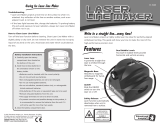
Nomenclature and Functions
Handle
Rotary head
Battery compartment lock
Battery holder
Laser emitting window
Beam aperture
Leveling screw
Panel
RL-VH3C Magnetic Scanning Target
Magnet
Datum line
Index
Index
Wall Mount 1C
Clamp lever
Laser Mounting
screw
Elevation
clamp knob
Reflectors

10
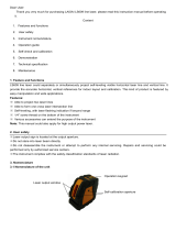
Control Panel
Auto/manual leveling control
Leveling lamp
Power switch
Manual mode lamp
Mode switch control
Scan mode
Laser sensor mode
Laser pointing mode
X/Y axis selection key
X/Y axis lamp
Head rotates slowly,
searching for Magnetic
Scanning Target. When
target is placed in beam
path, laser rapidly scans
back and forth on target.
Laser sensor mode
Head rotates at 300 rpm.
Use this setting when using
an optional electronic laser
sensor such as the Topcon
LS-70.
Head stops rotating and the
beam can be positioned by
manually turning the head.
Select X or Y axis for
manual beam sloping.
ON: Manual leveling mode
OFF: Auto-leveling mode
ON/OFF of Auto-leveling. To turn
off the auto-leveling, press this
key twice. To turn on the auto-lev-
eling again, press this key once.
Circular level for
vertical operation
Flashing: Laser is leveling
On: Auto-leveling is completed
(RL-VH3C remote control model has
standby mode)
Laser mode is switched
alternately as follows.
Speed control
With 'Laser Point-
ing Mode'
selected, the rota-
tion speed of the
head can be
changed.
Alignment
control
Low battery alert

11
Preparation For Use
Battery Installation
For battery placement or replacement instructions, see Maintaining Power Sources section,
page 19.
Instrument Set-up Procedure
Horizontal Rotation
1 Set the instrument on any smooth surface that is
within ±5° of true level. The RL-VH3C auto-level
system will not function if the unit is placed more
that 5° out of level. For best operation, it is recom-
mended that it be mounted to a tripod or the Top-
con Wall Mount Model 1C (provided).
Slope can be set in both axes, X and Y. See "Setting
Slope" section, page 16.
Leveling range
Horizontal

12
Vertical Rotation
1 Place the instrument on its back as shown in the illustra-
tion.
2 Turn the leveling screw on the instrument until the bubble
is centered in the circular level vial.
Battery Warning Lamp
Flashing : The power is low
ON Solid: Dead batteries
Replace the batteries with new ones.
Auto-leveling lamp
Flashing : Auto-leveling is in process. When automatic leveling is almost complete, the
flashing rate will be slow. The head will not rotate and the laser beam will not
emit during the auto-leveling process.
ON Solid: Auto-leveling is complete.
The rotary head is active and emits the laser beam.
To turn automatic leveling off
To turn OFF the auto-leveling function (manual mode), press the Auto-Manual control pad
twice in quick succession. The manual mode indicator light will illuminate. The instrument
can be positioned in any direction, the laser beam remains on and the head will rotate.
IMPORTANT: In manual mode, the laser beam will not shut off if disturbed! To return to Auto-
leveling mode, press Auto/Manual control pad once.

13
Operation
Scanning Mode
In scan mode, the laser rotates slowly, "searching" for the Magnetic Scanning Target. When
the target is properly placed in the beam path, the laser beam will scan rapidly back and forth
on the target and "track" the target as it is moved in its path.
1 To change to scanning mode when operating, press the Mode Control Pad.
2 To initiate target scanning, place the Magnetic Scanning Target in the beam path with the
reflective strips facing toward the laser.
3 To end target scanning and resume searching beam, remove target from beam path.
Vertical rotation
Horizontal rotation
Set scanning mode
Face the target toward the instrument to start scanning.

14
Laser Sensor Mode
For long range or outdoor applications, the instrument can be used with an optional elec-
tronic laser sensor. The Topcon models LS-70B or LS-70A are recommended. Press the
Mode Control Pad to select Laser Sensor Mode. The beam rotates at 300 rpm in this setting.
Laser Pointing Mode (stop)
This mode stops rotation and allows the laser beam to be pointed
by manually rotating the head. Press the mode control pad to select
Laser Pointing Mode. Beam rotation stops in this mode.
Changing rotation speed
(only available in Laser Pointing Mode)
After selecting Laser Pointing mode, press either Speed Control
pad to change rotation speed. The right pad increases the rotation
speed. The left pad reduces the rotation speed.
Laser pointing

15
Height Alert function
When auto-leveling is active, this function prevents the instrument from operating if it is dis-
turbed. This serves as a reminder to the user that to insure accurate control, the height of the
beam should be re-checked after the unit has been disturbed.
1 To activate the Height Alert function, depress and
hold the left Alignment control pad (see page 10) on
the control panel while turning on the instrument by
pressing the Power control pad. The three LEDs
(Leveling, Manual, Battery) will flash at the same time
for three seconds.
2 When this function is active and the unit is disturbed,
three visible LEDs will rapidly flash.
3 To re-activate auto-leveling and check the beam height, turn the unit off, then on again by
pressing the Power control pad twice. After auto-leveling is complete, check the beam
height to confirm it has not changed.
4 The Height Alert function is now inactive. To re-activate, turn unit off and repeat step 1.
Battery LED
Leveling LED
Manual LED

16
Setting Slopes
The laser beam can be manually sloped in either the
X or Y axis (single slope) or both axes (compound
slope).Using the Slope Control pads (see page 10),
the beam can be electronically raised or lowered 5
degrees above or below the inclination of the instru-
ment. This means that slopes up to 5 degrees can
be obtained if the instrument is set up on a level sur-
face. For slopes greater than 5 degrees, the instru-
ment must be manually positioned to within 5 degrees of the slope desired.
Horizontal
Inclination of the
instrument
X axis
Y axis
Single Axis
Dual Axes
Compound slope

17
How to set slopes
1 Turn the instrument on by pressing the Power control pad. Auto-leveling will start.
2 Press the X/Y Axis Selection control pad once after auto-leveling is complete (see page
10). The X axis lamp will flash. To change to Y axis, press the X/Y pad once again. Press-
ing the X/Y pad toggles between X and Y axis selection.
3 Select Laser Pointing mode to stop beam rotation and manu-
ally align the beam over the X axis (see illustration on previ-
ous page).
4 To move the laser beam up or down, press and hold the right
or left Alignment Control pad. The Manual mode lamp will
illuminate. The flashing X axis lamp will change to solid after
several seconds indicating slope has been entered in the X
axis.
5 To set a compound slope, repeat steps 2 to 4 for the Y axis.
To cancel slope settings
Press the Manual Mode pad. The instrument returns to auto-
leveling mode.
Setting slope in Y axis
Raise or lower the laser beam by pressing the right or left Alignment Control pad.
Sample; Laser pointing mode
Move the beam up or down by
pressing the right or left align-
ment keys

18
Line Control (manual vertical beam alignment)
1 Position the instrument for vertical operation as
instructed on page 12.
2 Press the Power Control pad to turn unit on.
When auto-leveling is complete, the laser beam
will be emitted.
3 Select the Laser Pointing operating mode and
using the laser beam, position the unit so the
beam aperture is directly over point A and is
roughly in line with point B (see illustration).
4 Rotate the head so the beam is pointing toward
point B. Press either one of the Alignment Con-
trol pads to move the beam right or left until it is
precisely aligned to point B.
5 Select the operating mode using the Mode Con-
trol pad best suited for your application.
Note
• While an alignment control pad is pressed the auto-leveling beam shut-off
will not operate.
• To aid in beam alignment, Vertical Alignment targets are available from Top-
con.
Page is loading ...
Page is loading ...
Page is loading ...
Page is loading ...
Page is loading ...
Page is loading ...
Page is loading ...
Page is loading ...
Page is loading ...
Page is loading ...
Page is loading ...
Page is loading ...
Page is loading ...
Page is loading ...
Page is loading ...
Page is loading ...
Page is loading ...
Page is loading ...
Page is loading ...
Page is loading ...
Page is loading ...
/