Honeywell MS1690 User guide
- Category
- Bar code readers
- Type
- User guide
This manual is also suitable for

METROLOGIC INSTRUMENTS, INC.
MS1690 Focus
®
Series
Area Imaging Bar Code Scanner
Installation and User's Guide

Copyright
© 2008 by Metrologic Instruments, Inc. All rights reserved. No part of this
work may be reproduced, transmitted, or stored in any form or by any means
without prior written consent, except by reviewer, who may quote brief
passages in a review, or provided for in the Copyright Act of 1976.
Trademarks
Metrologic is a registered trademark of Metrologic Instruments, Inc.
Products identified in this document are hereby acknowledged as
trademarks, registered or otherwise, of Metrologic Instruments, Inc. or their
respective companies.

ii
T
ABLE OF
C
ONTENTS
Introduction
Product Overview ............................................................................................. 1
Scanner and Accessories................................................................................. 2
Scanner Components....................................................................................... 4
The PowerLink Cable ....................................................................................... 5
Labels............................................................................................................... 6
Maintenance..................................................................................................... 6
Installing the Scanner to the Host System
RS232 MS1690-14........................................................................................... 7
Keyboard Wedge MS1690-47 .......................................................................... 8
Stand Alone Keyboard MS1690-47 .................................................................. 9
IBM MS1690-11 ............................................................................................. 10
Full Speed USB MS1690-40 (Integrated)....................................................... 11
Low Speed USB MS1690-38 (Integrated) ...................................................... 11
Stand Kits
Stand Components, MLPN 46-00147............................................................. 12
Hard Mounting the Stand................................................................................ 13
Assembling the Stand .................................................................................... 14
Scanner Operation
Two Default Modes of Operation.................................................................... 15
Audible Indicators........................................................................................... 16
Visual Indicators ............................................................................................. 17
Failure Modes................................................................................................. 18
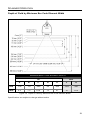
Depth of Field by Minimum Bar Code Element Width .................................... 19
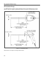
IR Activation Range........................................................................................ 20
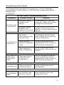
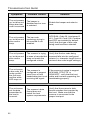
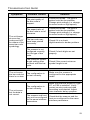
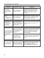
Troubleshooting Guide ....................................................................................... 21
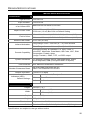
Design Specifications ......................................................................................... 25
Applications and Protocols ................................................................................. 27
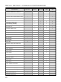
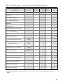
Default Settings – Communication Parameters.................................................. 28

iii
T
ABLE OF
C
ONTENTS
Configuration Modes .......................................................................................... 32
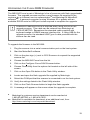
Upgrading the Flash ROM Firmware.................................................................. 33
Scanner and Cable Terminations
Scanner Pinout Connections.......................................................................... 34
Cable Connector Configurations .................................................................... 36
Limited Warranty ................................................................................................ 38
Regulatory Compliance
Safety ............................................................................................................. 39
EMC ............................................................................................................... 40
Patents ............................................................................................................... 42
Index .................................................................................................................. 43
Contact Information and Office Locations........................................................... 45

1
I
NTRODUCTION
Product Overview
Metrologic's MS1690 Focus
®
series of high performance hand-held area imaging
bar code scanners utilizes high-resolution CMOS imaging sensors for superior
image quality. Omniplanar, Inc.’s SwiftDecoder
®
software, for provides reliable
decoding of both 1D and 2D bar code symbologies. Sharp images can be
captured and transmitted in a variety of outputs including: .jpg, .bmp, and .tiff.
Omnidirectional scanning capabilities and an extended depth of field provides
aggressive scanning of all standard 1D, RSS, PDF417, microPDF, Composite,
Matrix and Postal Codes symbology types. Firmware updates are easily loaded
via Flash ROM.
The MS1690 series provides an extended depth of field and a built in object
detection sensor (IR) that instantly turns on the scanner when an object is
presented within the scanner’s field of view. Automatic in-stand detection
switches the scanner to a “presentation” mode for convenient in-stand scanning.
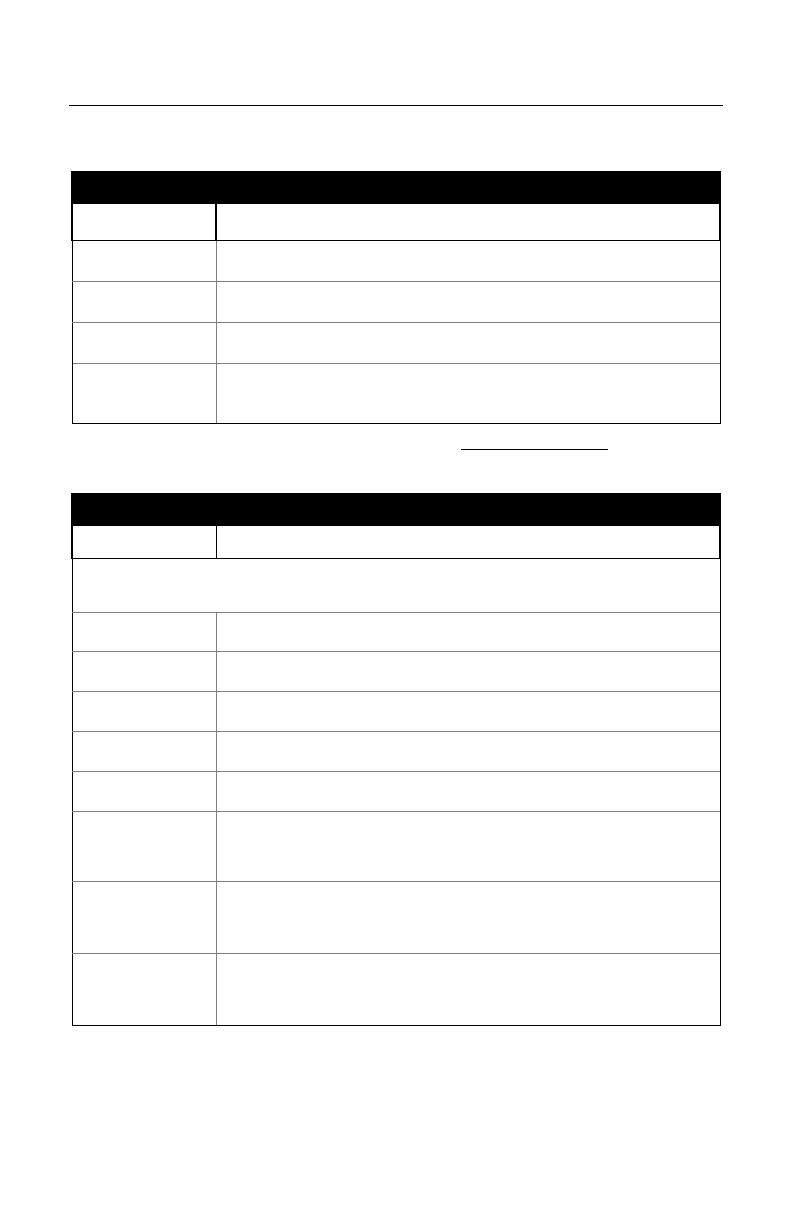
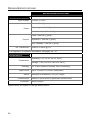
Model Interface
MS1690 – 11 IBM 468X/469X, RS232-TXD, RXD, RTS, CTS
MS1690 – 14 RS232 (TX, RX, RTS, CTS, DTR)
MS1690 – 38 Low Speed USB
MS1690 – 40 Full Speed USB
MS1690 – 47
Keyboard Wedge, Stand-Alone Keyboard and
RS232 Transmit/Receive
2
I
NTRODUCTION
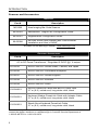
Scanner and Accessories
B
ASIC
K
IT
Part # Description
MS1690 Area Imaging Bar Code Scanner
00-02544 MetroSelect
®
Single-Line Configuration Guide*
00-02281 Supplemental Configuration Guide*
00-02098
MS1690 Series Area Imaging Bar Code Scanner
Installation and User’s Guide*
*
Available on the Metrologic website - www.metrologic.com
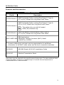
O
PTIONAL
A
CCESSORIES
Part # Description
AC to DC Power Transformer - Regulated 5.2VDC @ 1 A output.
46-00525 90VAC-255VAC United States, Canada, and Japan
46-00526 90VAC-255VAC Continental European
46-00527 90VAC-255VAC United Kingdom
46-00528 90VAC-255VAC Australia
46-00529 90VAC-255VAC China
53-53000-3
RS232 PowerLink Cable with Built in Power Jack
2.7 m (9 ft.) coiled cord, long strain relief, black
53-53002-3
Keyboard Wedge PowerLink Cable with Adapter Cable
2.7 m (9 ft.) coiled cord, long strain relief, black
53-53020-3
Stand Alone Keyboard PowerLink Cable
2.7 m (9 ft.) coiled cord, long strain relief, black
Other items may be ordered for the specific protocol being used. To order additional items,
contact the dealer, distributor or call Metrologic’s Customer Service Department at
1-800-ID-METRO or 1-800-436-3876.
3
I
NTRODUCTION
Scanner and Accessories
O
PTIONAL
A
CCESSORIES
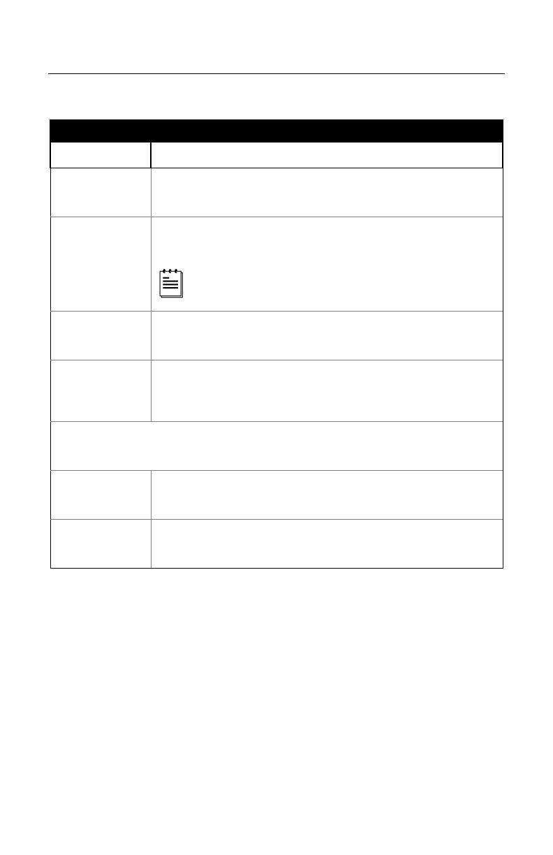
Part # Description
53-53213x-N-3
USB Full Speed Cable, Locking Plus-Power™ Type A,
2.7 m (9 ft.) coiled cord, long strain relief, black
53-53214x-N-3
USB Full Speed Cable, Locking Plus-Power™ Type A,
4.5 m (15 ft.) coiled cord, long strain relief, black
This cable is for use with full speed
USB (-40) interface only.
53-53235x-N-3
USB Low Speed Communication Cable Type A,
2.7 m (9 ft.) coiled cord, long strain relief, black
MVC-2MPC-IB9
IBM Applications
Metrologic Voltage Converter (MVC) Cable*
±12VDC to +5.2VDC
* Contact a Metrologic customer service representative for additional
information on the MVC cable series and the host connections available.
00-02001 MS1690 Stand (46-00147) Installation Guide
46-00147 Modular Presentation Stand
Other items may be ordered for the specific protocol being used. To order additional items,
contact the dealer, distributor or call Metrologic’s Customer Service Department at
1-800-ID-METRO or 1-800-436-3876.
4
I
NTRODUCTION
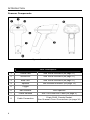
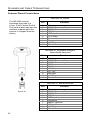
Scanner Components
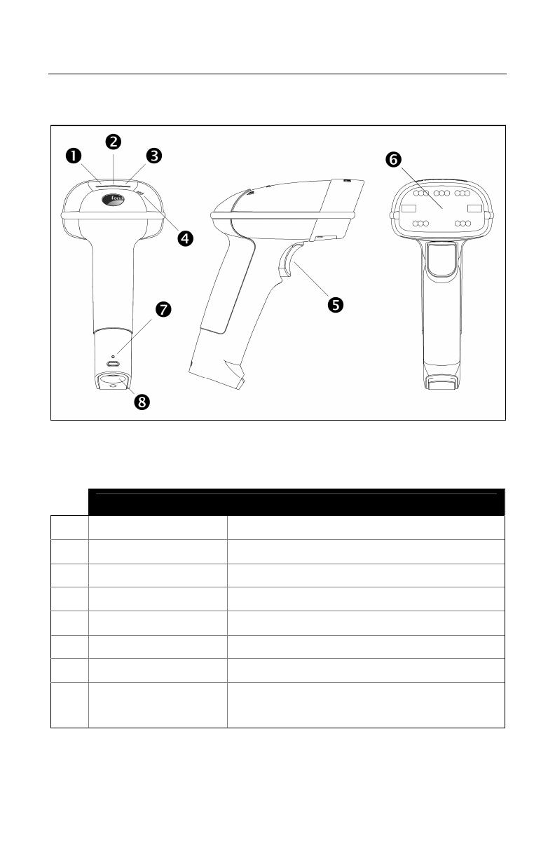
Figure 1. Scanner Components
Item Description
1 Yellow LED See Visual Indicators (on page 17)
2 White LED See Visual Indicators (on page 17)
3 Blue LED See Visual Indicators (on page 17)
4 Speaker See Audible Indicators (on page 16)
5 Trigger
6 Red Window LED Aperture
7 Cable Release See The PowerLink Cable (on page 5)
8 Cable Connection
10-pin RJ45, Female Socket,
See Scanner Pinout Connections (on page 34)
5
I
NTRODUCTION
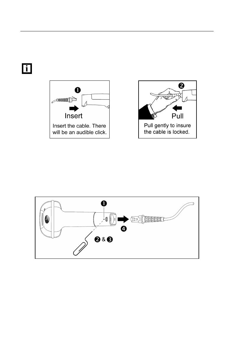
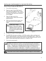
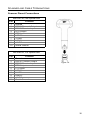
The PowerLink Cable
Connecting
Important: If the PowerLink cable is not fully ‘latched’ the unit can
power intermittently.
Figure 2. Figure 3.
Disconnecting
Before removing the cable from the scanner, Metrologic recommends that the
power on the host system is off and the power supply has been disconnected
from the PowerLink cable.
Figure 4. Releasing the PowerLink Cable
1. Locate the small ‘pin-hole’ on the handle of the unit near the cable.
2. Bend an ordinary paperclip into the shape shown above.
3. Insert the paperclip (or other small metallic pin) into the small ‘pin-hole’.
4. There will be a faint ‘click’ when the lock is released. Pull gently on the
strain-relief of the PowerLink cable to remove the cable from the unit.

6
I
NTRODUCTION
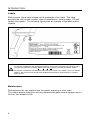
Labels
Each scanner has a label located on the underside of the head. This label
provides the unit’s model number, date of manufacture, serial number, CE and
caution information. The following figure gives an example of the label and its
location.
Figure 5. Label Sample and Location
Caution:
To maintain compliance with applicable standards, all circuits connected to the scanner must
meet the requirements for SELV (Safety Extra Low Voltage) according to EN/IEC 60950-1.
To maintain compliance with standard CSA-C22.2 No. 60950-1/UL 60950-1 and norm EN/IEC
60950-1, the power source should meet applicable performance requirements for a limited
power source.
Maintenance
Smudges and dirt can interfere with the proper scanning of a bar code.
The output window should be routinely cleaned with glass cleaner sprayed onto a
lint free, non-abrasive cloth.

7
I
NSTALLING THE
S
CANNER TO THE
H
OST
S
YSTEM
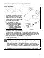
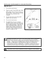
RS232 MS1690-14
1. Turn off the host device.
2. Plug the male 10-pin RJ45 end of
the PowerLink cable into the 10-pin
socket on the MS1690. There will be
an audible click when the connector
lock engages.
3. Connect the 9-pin D-type connector
of the communication cable to the
proper COM port of the host device.
4. Plug the power supply into the power
jack on the PowerLink cable.
Check the AC input
requirements of the power
supply to verify the voltage
matches the AC outlet.
The outlet must be located
near the equipment and be
easily accessible.
5. Connect AC power to the transformer.
6. The MS1690 will start to initialize. All LEDs (yellow, white, and blue) will
light for approximately 2 seconds then start to alternately flash. When the
scanner has finished initializing the LEDs will stop flashing and the unit will
beep 3 times indicating that the scanner is ready for use.
7. Turn on the host device.
Plugging the scanner into a port on the host system does not guarantee
that scanned information will be communicated properly to the host
system. The scanner is shipped from the factory configured with default
settings. Please refer to the MetroSelect Single-Line Configuration
Guide (
MLPN
00-02544) or MetroSet2’s help files for instructions on
changing the scanner’s configuration. In addition, please check that the
scanner and host system are using the same communication protocol.
See power source caution statement located on page 6 of this manual.
Figure 6.

8
I
NSTALLING THE
S
CANNER TO THE
H
OST
S
YSTEM
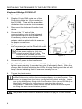
Keyboard Wedge MS1690-47
1. Turn off the host device.
2. Plug the 10-pin RJ45 male end of the
PowerLink cable into 10-pin socket on
the MS1690. There will be an audible
click when the connector lock engages.
3. Disconnect the keyboard from the host
device.
4. Connect the “Y” ends of the
communication cable to the keyboard
and keyboard port on the host device.
If necessary use the male/female
adapter cable supplied with the scanner
for proper connections.
5. Plug the external power supply (required)
into the power jack on the PowerLink cable.
Check the AC input requirements
of the power supply to verify the
voltage matches the AC outlet. The
outlet must be located near the
equipment and be easily accessible.
6. Connect AC power to the transformer.
7. The MS1690 will start to initialize. All LEDs (yellow, white, and blue) will
light for approximately 2 seconds then start to alternately flash. When the
scanner has finished initializing the LEDs will stop flashing and the unit will
beep 3 times indicating that the scanner is ready for use.
8. Turn on the host device.
Plugging the scanner into a port on the host system does not guarantee that
scanned information will be communicated properly to the host system. The
scanner is shipped from the factory configured with default settings. Please
refer to the MetroSelect Single-Line Configuration Guide (
MLPN
00-02544) or
MetroSet2’s help files for instructions on changing the scanner’s
configuration. In addition, please check that the scanner and host system
are using the same communication protocol.
See power source caution statement located on page 6 of this manual.
Figure 7.

9
I
NSTALLING THE
S
CANNER TO THE
H
OST
S
YSTEM
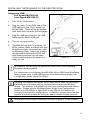
Stand Alone Keyboard MS1690-47
1. Turn off the host device.
2. Plug the male 10-pin RJ45 end of
the PowerLink cable into the 10-pin
socket on the MS1690. There will be
an audible click when the connector
lock engages.
3. Plug the other end of the
communication cable into the host’s
keyboard port.
4. Plug the external power supply into
the power jack on the PowerLink
cable.
Check the AC input
requirements of the power
supply to verify the voltage
matches the AC outlet. The
outlet must be located near
the equipment and be easily
accessible.
5. Connect AC power to the transformer.
6. The MS1690 will start to initialize. All LEDs (yellow, white, and blue) will
light for approximately 2 seconds then start to alternately flash. When the
scanner has finished initializing the LEDs will stop flashing and the unit will
beep 3 times indicating that the scanner is ready for use.
7. Turn on the host device.
Plugging the scanner into a port on the host device does not guarantee
that scanned information will be communicated properly to the host
device. The scanner is shipped from the factory configured with default
settings. Please refer to the MetroSelect Single-Line Configuration
Guide (
MLPN
00-02544) or MetroSet2’s help files for instructions on
changing the scanner’s configuration. In addition, please check that the
scanner and host system are using the same communication protocol.
See power source caution statement located on page 6 of this manual.
Figure 8.
10
I
NSTALLING THE
S
CANNER TO THE
H
OST
S
YSTEM
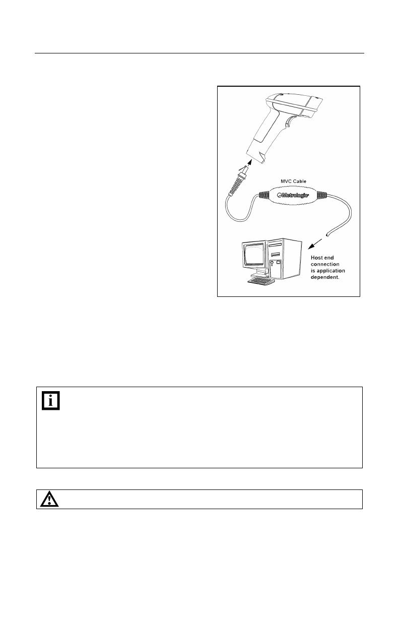
IBM MS1690-11
1. Turn off the host device.
2. Plug the male 10-pin RJ45 end of the
MVC cable into the 10-pin socket on
the MS1690. There will be an audible
click when the connector lock
engages
3. Connect the other end of the MVC
cable to the host device.
4. Turn on the host device.
5. The MS1690 will start to initialize.
All LEDs (yellow, white, and blue) will
light for approximately 2 seconds then
start to alternately flash. When the
scanner has finished initializing the
LEDs will stop flashing and the unit
will beep 3 times indicating that the
scanner is ready for use.
Plugging the scanner into a port on the host system does not guarantee
that scanned information will be communicated properly to the host
system. The scanner is shipped from the factory configured with default
settings. Please refer to the MetroSelect Single-Line Configuration
Guide (
MLPN
00-02544) or MetroSet2’s help files for instructions on
changing the scanner’s configuration. In addition, please check that the
scanner and host system are using the same communication protocol.
See power source caution statement located on page 6 of this manual.
Figure 9.

11
I
NSTALLING THE
S
CANNER TO THE
H
OST
S
YSTEM
Integrated USB:
Full Speed MS1690-40
Low Speed MS1690-38
1. Turn off the host device.
2. Plug the male 10-pin RJ45 end of the
USB cable into the 10-pin socket on
the MS1690. There will be an audible
click when the connector lock engages.
3. Plug the USB type A end of the USB
cable into the host’s USB port.
4. Turn on the host device.
5. The MS1690 will start to initialize. All
LEDs (yellow, white, and blue) will light
for approximately 2 seconds then start
to alternately flash. When the scanner
has finished initializing the LEDs will
stop flashing and the unit will beep
3 times indicating that the scanner is
ready for use.
As a default, the MS1690-38 leaves the factory with USB Keyboard
Emulation Mode enabled.
For information on configuring the MS1690-38 for USB Serial Emulation
Mode, please refer to the USB section of the MetroSelect Single-Line
Configuration Guide (
MLPN
00-02544).
Plugging the scanner into a port on the host device does not guarantee
that scanned information will be communicated properly to the host
device. The scanner is shipped from the factory configured with default
settings. Please refer to the MetroSelect Single-Line Configuration
Guide (
MLPN
00-02544) or MetroSet2’s help files for instructions on
changing the scanner’s configuration. In addition, please check that the
scanner and host system are using the same communication protocol.
See power source caution statement located on page 6 of this manual.
Figure 10.
12
S
TAND
K
ITS
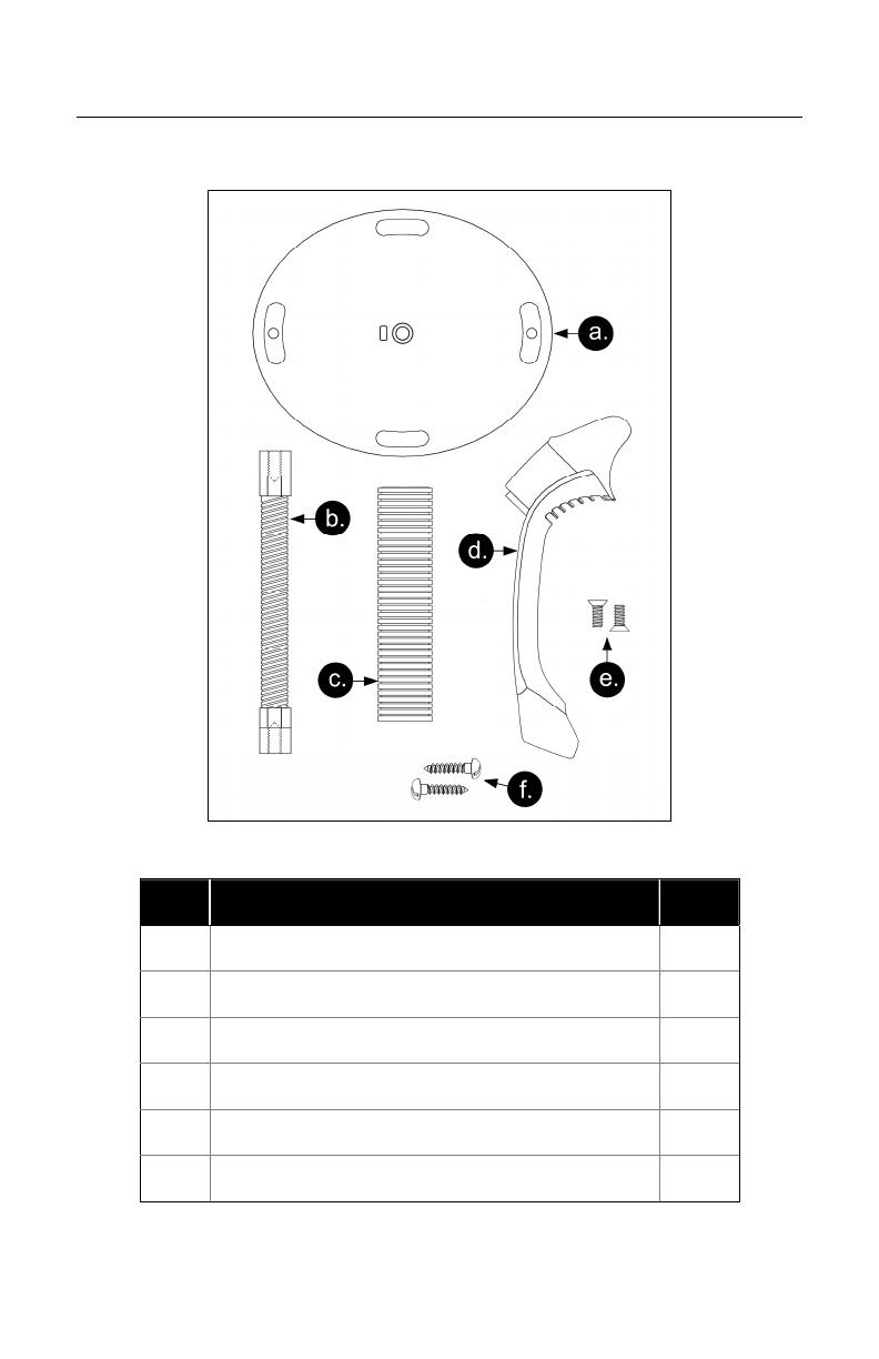
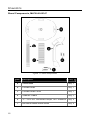
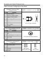
Stand Components, MLPN 46-00147
Figure 11. Stand Components
Item Description Qty.
a. Stand Base Qty. 1
b. Flexible Shaft Qty. 1
c. Flexible Shaft Cover Qty. 1
d. Scanner Cradle Qty. 1
e. ¼" – 20 x 3/8" Flat Head Phillips, 100° Undercut Qty. 2
f. #8 Round Head Wood Screw Qty. 2
13
S
TAND
K
ITS
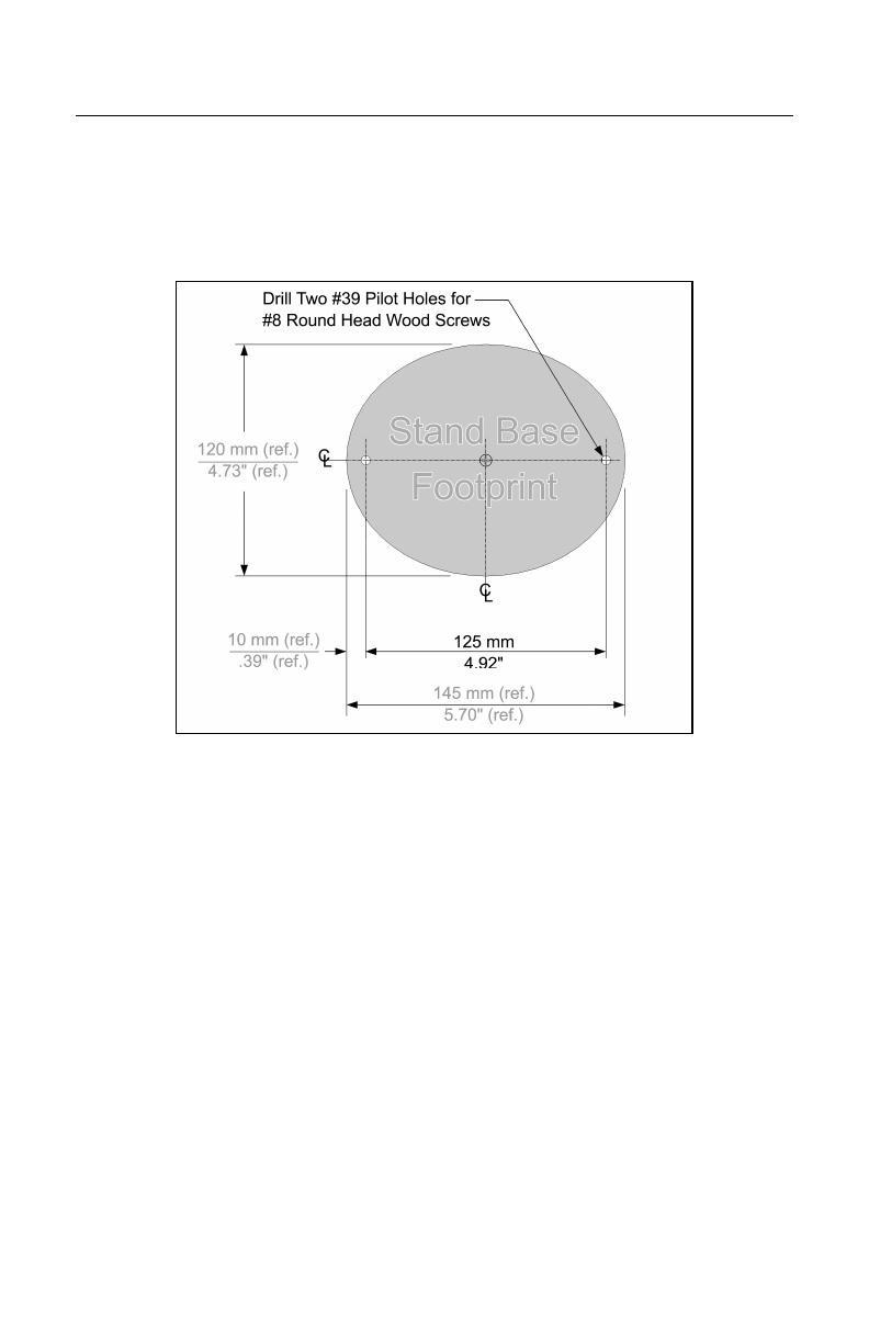
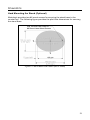
Hard Mounting the Stand (Optional)
Metrologic provides two #8 wood screws for securing the stand base to the
counter top. The following figure provides the pilot hole dimensions for securing
the stand base.
Figure 12. Stand Base Hole Pattern (Not to Scale)
14
S
TAND
K
ITS
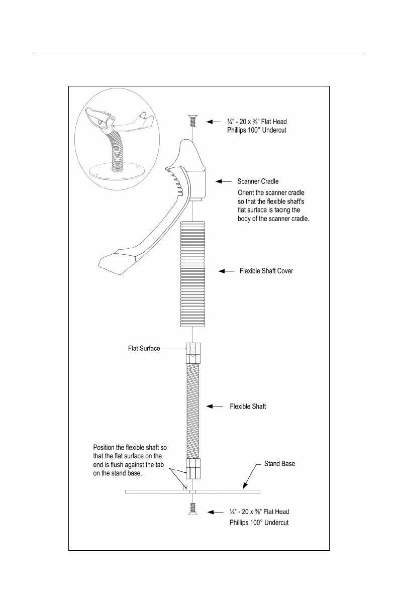
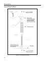
Assembling the Stand
Figure 13. Assembling the Stand

15
S
CANNER
O
PERATION
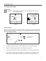
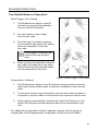
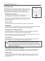
Two Default Modes of Operation*
Multi-Trigger, Out of Stand
1. The IR detects an object in the IR
activation range and automatically
turns on linear illumination.
2. Aim the scanner’s line of light
over the bar code.
3. Pull the trigger to initiate scanning.
The scanner’s light output will start to
flash as it attempts to scan the
bar code.
If the trigger is released the
scanner will stop trying to
scan.
4. When scanner successfully reads the
bar code it will beep once, the white
LED will flash and the decoded data
will be transmitted to the host.
Presentation, In-Stand
1. The IR detects an object in the IR activation range and the scanner’s
light output automatically starts to flash as it attempts to scan the bar
code.
2. The scanner continuously attempts to scan the bar code until either it
succeeds or the bar code is removed from the scanner’s field of view.
3. When scanner successfully reads the bar code it will beep once, the
white LED will flash and the decoded data will be transmitted to the
host.
* For additional configurable modes of operation, please refer to the Area
Imaging Bar Code Supplemental Configuration Guide (
MLPN
00-02281).
Figure 14. Multi-Trigger, Out-of-Stand

16
S
CANNER
O
PERATION
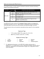
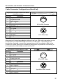
Audible Indicators
When the MS1690 is in operation, the scanner provides audible feedback.
These sounds indicate the status of the scanner. Eight settings are available for
the tone of the beep (normal, 6 alternate tones and no tone). To change the
tone, refer to the MetroSelect Single-Line Configuration Guide,
MLPN
00-02544 or
MetroSet2’s help files.
One Beep
When the scanner successfully reads a bar code it will beep once and the
white LED will turn on indicating data is being transmitted.
If the scanner does not beep once and the white light does not turn on, then
the bar code has not been successfully read.
Short Razzberry Tone
This tone is a failure indicator (see Failure Modes on page 18).
Long Razzberry Tone
This tone is a failure indicator (see Failure Modes on page 18).
Three Beeps - At Power Up
When The MS1690 first receives power it will start an initialization sequence.
All LEDs (yellow, white, and blue) will light for approximately 2 seconds then
start to alternately flash. When the scanner has finished initializing the LEDs
will stop flashing and the unit will beep 3 times indicating that the scanner is
ready for use.
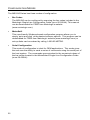
Three Beeps - Configuration Mode
When entering configuration mode, the white LED will flash while the scanner
simultaneously beeps three times. The white and blue LEDs will continue to
flash while in this mode. Upon exiting configuration mode, the scanner will
beep three times, and the LEDs will stop flashing.
When configured, 3 beeps can also indicate a communications timeout during
normal scanning mode.
When using single-code-configuring, the scanner will beep three times:
a normal tone followed by a short pause, a high tone and then a low tone.
This indicates that the single configuration bar code has successfully
configured the scanner.
Page is loading ...
Page is loading ...
Page is loading ...
Page is loading ...
Page is loading ...
Page is loading ...
Page is loading ...
Page is loading ...
Page is loading ...
Page is loading ...
Page is loading ...
Page is loading ...
Page is loading ...
Page is loading ...
Page is loading ...
Page is loading ...
Page is loading ...
Page is loading ...
Page is loading ...
Page is loading ...
Page is loading ...
Page is loading ...
Page is loading ...
Page is loading ...
Page is loading ...
Page is loading ...
Page is loading ...
Page is loading ...
Page is loading ...
Page is loading ...
Page is loading ...
Page is loading ...
-
 1
1
-
 2
2
-
 3
3
-
 4
4
-
 5
5
-
 6
6
-
 7
7
-
 8
8
-
 9
9
-
 10
10
-
 11
11
-
 12
12
-
 13
13
-
 14
14
-
 15
15
-
 16
16
-
 17
17
-
 18
18
-
 19
19
-
 20
20
-
 21
21
-
 22
22
-
 23
23
-
 24
24
-
 25
25
-
 26
26
-
 27
27
-
 28
28
-
 29
29
-
 30
30
-
 31
31
-
 32
32
-
 33
33
-
 34
34
-
 35
35
-
 36
36
-
 37
37
-
 38
38
-
 39
39
-
 40
40
-
 41
41
-
 42
42
-
 43
43
-
 44
44
-
 45
45
-
 46
46
-
 47
47
-
 48
48
-
 49
49
-
 50
50
-
 51
51
-
 52
52


Honeywell MS1690 User guide
- Category
- Bar code readers
- Type
- User guide
- This manual is also suitable for
Ask a question and I''ll find the answer in the document
Finding information in a document is now easier with AI
Related papers
-
Metrologic 5S-5S235-3 User manual
-
Metrologic Orbit MS7120-38 User manual
-
Honeywell MS7120 User manual
-
Honeywell AP-010-BT User manual
-
Metrologic Orbit MS7120 User guide
-
Honeywell MS5145 Eclipse User guide
-
-
Honeywell Vuquest 4980 User guide
-
-
Other documents
-
Metrologic MS1890 Series User manual
-
-
-
Metrologic MS1690 User manual
-
-
-
-
Metrologic Instruments MS9590i User manual
-
-