Metro DataVac PBH3060L Assembly Instructions
- Type
- Assembly Instructions

InterMetro Industries Corporation
North Washington Street
Wilkes-Barre, PA 18705
(717) 825-2741
Revision C
WB
S
ORK ENCH
YSTEM
Assembly Instructions
L01-194 9/2008
OVERHEAD LIGHTGRID ACCESSORIES
FLAT
WASHERS
BLACK EDGE
#10 X 1 3/4"
PAN HEAD SCREW
#10 STAR WASHER -
MAKE SURE IT DIGS
INTO SURFACE!
KEP NUT
1. Drill 3/16" dia. hole through benchtop
near one of the rear corners.
2. Assemble grounding wire as shown.
3. To ensure ESD properties, tighten nut
securely and connect other end of bench
grounding wire to facility ground.
Due to normal shrinkage and expansion
of laminates, it may be necessary to
retighten this connection. Periodically
check for continuity to ground.
NOTE: Benchtop is conductive only if
its edge banding is black.
First attach Light Supports
to rear Posts on plastic
sleeves positioned at the
top grooves. Then attach
Light to Supports as shown
above by assembling the
clamps around the
Supports, with the bolt
dropping down through the
middle of the Support.
Secure and tighten with
threaded plastic Knob as
shown.
ESD BENCHTOP
GROUNDING
INSTRUCTIONS
BULBS NOT
INCLUDED
GROUNDING
WIRE
PBL3060L
PBL3060LP
PBL3072L
PBL3072LP
PBL3060C
PBL3060CP
PBL3072C
PBL3072CP
PBH3060L
PBH3060LP
PBH3072L
PBH3072LP
PBH3060C
PBH3060CP
PBH3072C
PBH3072CP
Low Profile
Low Profile with Power
Low Profile
Low Profile with Power
Low Profile
Low Profile with Power
Low Profile
Low Profile with Power
High Profile
High Profile with Power
High Profile
High Profile with Power
High Profile
High Profile with Power
High Profile
High Profile with Power
MODEL NO. DESCRIPTION
Attach Bin Holders by first sliding top corner tabs up behind a horizontal Grid
rod, then press Bin Holder against the Grid and slide down until the Bottom
corner tabs are behind the next horizontal Grid rod down.
MONITOR SHELF
(END VIEW)
MONITOR SHELF
GRID SHELF
GRID SHELF
(END VIEW)
GRID
(END VIEW)
TO
FRONT
CATALOG/FILE HOLDER
(END VIEW)
HANGING FILE HOLDER
HANGING FILE HOLDER
(END VIEW)
CATALOG/FILE
HOLDER
11" BIN
HOLDER
22" BIN
HOLDER
SUPPORT
BRACE (2)
GRID
ACCESSORIES
TILT-ADJUSTING
SCREW - USE
HEX WRENCH
USE TWO
TIE WRAPS
TO SECURE
CORD TO
POST

8
9
3
4
5
1
12
10
2
A
7
11
6
F
I. EXPLODED VIEW - PARTS AND ACCESSORIES GUIDE
GRID ACCESSORIES
E
D
G
L
I
H
J
B
C
M
K
Front Post
Rear Post (slotted) - Low Profile
Rear Post (slotted) - High Profile
Plastic Split-Sleeves
Footrest Frame
Top Frame
Adjustable Foot Assembly
Bench Top
Top Brace (Rear Stringer)
Power Strip with Brackets
Ledge (60" long only)
Aluminum Split-Sleeves
High
Profile
Workbench
High Profile
Workbench
with Power
Low
Profile
Workbench
Low Profile
Workbench
with Power
1.
2.
3.
4.
5.
6.
7.
8.
9.
10.
11.
12.
2
-
2
6
1
1
4
1
1
-
1
4
2
-
2
6
1
1
4
1
1
1
1
4
2
2
-
4
1
1
4
1
-
-
1
4
2
2
-
4
1
1
4
1
-
1
1
4
KEY
PBA-LA60
PBA-1260CQ
PBA-BBCQ
PBA-SD6D
PBA-AD6D
PBA-SD12D
PBA-AD12D
PBA-GPCQ
PBA-MS
PBA-CHD
PBA-GSD
PBA-1BH
PBA-2BH
PBA-PFH
PBA-60PQ
A.
B.
C.
D.
-
-
E.
F.
G.
H.
I.
J.
K.
L.
M.
KEY MODEL # DESCRIPTION
DESCRIPTION
QUANTITY
MAIN COMPONENTS
AVAILABLE ACCESSORIES
Light Fixture
Cantilever Shelf
Bin Rail
6" Starter Drawer*
6" Add-on Drawer*
12" Starter Drawer*
12" Add-on Drawer*
Grid Panel
Monitor Shelf
Catalog/File Holder
Grid Shelf
11" Bin Holder
22" Bin Holder
Hanging File Folder
Power Strip
*Note:For Drawer with Lock, add 'L' to end of Model Number.
WEIGHT CAPACITIES
ELECTRICAL
SPECIFICATIONS
Work Surfaces -
PBA-1260CQ Cantilever Shelf -
PBA-GSD Grid Shelf -
PBA-MS Monitor Shelf -
Maximum Load on Grid -
1000 lbs. (453 kg) evenly distributed
weight
100 lbs. (45 kg) evenly distributed
weight
50 lbs. (23 kg) evenly distributed
weight
50 lbs. (23 kg) evenly distributed
weight
250 lbs. (113 kg) total
Light (PBA-LA60)
Power Strip (PBA-60PQ)
-ULListed.
- Accepts two 48" (122 cm) 32W
fluorescent bulbs (not included)
- Light Level: 70 foot candles (752 lux)
when measured at a distance of 39" (99
cm) from light to work surface in a
parallel position utilizing two 48"
(122 cm) 32W cool white
fluorescent bulbs.
- 7 ft. cord
- 6 outlets
- 115V, 15A, 60 Hz continuous service
- Includes illuminated ON/OFF switch
- Protected by 15A circuit breaker
- 9 ft. cord
X
37"
36"
35"
34"
33"
32"
31"
Do Not
Use
Bottom
Groove
LEVELING FOOT PAD

X
37"
36"
35"
34"
33"
32"
31"
Do Not
Use
Bottom
Groove
II. BASIC WORKBENCH ASSEMBLY
Locate the 2 front (unslotted) and 2 rear (slotted) Posts and the Footrest Frame. First lay carpet or
similar material down on floor to protect finish. Attach plastic sleeves at the first or second groove near
the bottom of each Post. Assemble the 4 Posts and the Footrest Frame as shown above, with the unit
on its back, by sliding the Posts up into the collars on the Footrest Frame.
Note that the Footrest can be attached either as
shown above or with the long footrest tube closer to the back of the bench. Put 4 Adjustable Foot
Assemblies together as shown above and install in the bottom ends of the 4 Posts. Set the bench
upright and seat the Footrest Frame collars firmly down onto the plastic sleeves, using a hammer and
block of wood or rubber mallet (to protect finish).
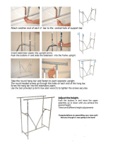
Should you ever desire to readjust bench height, carefully lay Workbench down on its back , grip foot
posts firmly with vice-grip pliers, then tap against pliers with hammer or mallet until Foot Assembly
comes back out of Post. Then move split sleeves to different groove locations and proceed as above.
Rotate Rear Posts care-
fully so the slots are facing exactly front and rear.
2
3
4
END VIEW
FOOTREST FRAME
H-FRAME IN PLACE
FRONT POST
FRONT POST
Set ALUMINUM
Split Sleeves on
TOP Groove
on front Post
Set
Sleeves on
the same
Groove
as on the
Front Posts
ALUMINUM
Split
FRONT OF
TOP FRAME
ROUND HOLES
KEYHOLE- SHAPED HOLES
KEYHOLE- SHAPED HOLES
ROUND HOLES
REAR
KEYHOLES
SHOULDER RIVETS
Set
Plastic
Split
Sleeves
on
first or
second
Groove
REAR POST - NOTE SLOTS FACING UP.
NOTE BLACK RIMS AT
BOTTOMS OF BLUE POSTS
BACK DOWN
HIGH PROFILE
LOW PROFILE
Set Benchtop in place on
the Top Frame and
ensure that it is centered
left-to-right and all the
way back against the
Rear Posts. Attach it
with the screws provided
as shown.
1
SMALLER
END
TOWARD
TOP
SMALL SPLIT SLEEVE
JAM NUT
FOOT PAD
LEVELING FOOT PAD
X
ADJUSTABLE FEET
To attach components: Begin by snapping a 2-piece plastic
sleeve together around each post at the groove indicated in
the instructions that follow. Be sure the smaller end of the
sleeve (and the ridge inside the sleeve) is toward the top of
the post. Note: for attaching the top frame, use the aluminum
split sleeves provided.
OPTION: ATTACH DRAWER ASSEMBLY
Attach Starter Drawer Assembly
as shown at left. First insert the
two straight pins on the back of the
drawer assembly into two ROUND
HOLES in the back of the top
frame (under the benchtop). Note
that drawer can be attached under
the top at several positions left-to-
right. Next, insert the shoulder
rivets on the top front of the
drawer assembly into two
KEYHOLES in the front of the top
frame. Be sure the rivets drop
down into the narrow parts of the
key holes and lock in place.
Optional Add-on Drawer attaches
to sides of Starter Drawer
Assembly with screws as shown
below.
HIGH PROFILE ONLY
TOP BRACE
5
High Profile only - attach Top Brace on
plastic sleeves set on the third groove
down from the top of each Rear Post.
4. After
Workbench
is upright in
desired
location,
rotate Foot
Pad for fine
adjustment,
then tighten
jam nut.
1. Thread jam nuts
half way onto the 4
Foot Pads as
shown, then screw
leveling feet into
foot posts - tighten jam nuts later.
2. Choose the approximate bench height you want and place the
small split sleeves on the appropriate grooves on the 4 Foot Posts
as shown at right (same groove on all 4).
3. Insert the completed Foot Assemblies into the bottom ends of the
blue bench posts.
Snap on
"C" Rings.
After placing the aluminum split sleeves on
the posts as shown, attach the top frame. Be
sure to orient the top frame correctly
Seat the frame firmly using a
hammer with a block of wood to protect the
finish. Then secure in place by tapping the
"C" rings into place.
so that
the front member that is welded directly to
the collars is positioned toward the front of
the bench.

1
2
To Front
III. GRID AND ACCESSORIES
TOP GRID SUPPORT BRACKET
BENCHTOP
BACK OF
TOP
FRAME
GRID
Drive screw (with
washer) through
Bracket, through
center hole on back of
Top Frame.
Snap QuikSlot Clips into the slots on the
backs of the Rear Posts as shown at left.
Hang Grid on QuikSlot Clips, then secure
to the Top Brace and the back of the Top
Frame as shown at right.
FOR SAFETY'S SAKE, BE
SURE TO CORRECTLY
INSTALL THE TOP AND
BOTTOM BRACKETS
Hang the bottom
bracket over the
bottom of the grid
at the center.
3
4
BIN BAR
OUTLET BAR
Attach Shelf to
Brackets through
the double wires.
CANTILEVER SHELF
CANTILEVER SHELF
CANTILEVER SHELF (END VIEW)
To attach cantilever shelf
brackets, follow the 3 steps
above, first hooking the top tab
of each shelf bracket into the
appropriate slot in the Rear Post,
and then swinging the other tabs
into the slots below. Be sure to
seat the shelf bracket firmly into
place - tap down lightly with a
rubber mallet or hammer and
wood block next to the Post if
necessary. Then position wire
shelf on top of brackets,
centered left-to-right. Attach
through the double wires to
brackets with screws as shown
above.
ADJUSTABLE
SHELF BRACKET
SLOTTED REAR POST
LEDGE
To install the ledge,
remove the backer
from the mounting
tape on the bottom
and apply to rear
edge of top as shown
at left. If you have a
72" top, center the
ledge left to right.
LEDGE
qwikSlot
Clip
OUTLET BAR
END VIEW
First attach 2 brackets
to rear posts as shown...
First attach 2
brackets to
rear posts
as shown...
...then attach Outlet Bar
between brackets with
screws provided.
...then attach Bin Bar
to brackets with screws
provided.
BIN
BAR
END
VIEW
Rotate Tab Up
to Lock in place.
Install qwikSLOT
clipsinthe4th&
5th slots below
the top brace.
Install qwikSLOT
clipsinthe6th&
7th slots above
the top frame.
Hang grid on 2nd hori-
zontal wire from the top
and the 3rd horizontal
wire from the bottom.
-
 1
1
-
 2
2
-
 3
3
-
 4
4


Metro DataVac PBH3060L Assembly Instructions
- Type
- Assembly Instructions
Ask a question and I''ll find the answer in the document
Finding information in a document is now easier with AI
Related papers
Other documents
-
 NewTechWood US-QD-PB-13-TK Installation guide
-
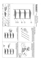
 Only Hangers 01-003CH Operating instructions
-
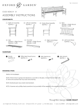 Oxford Garden Essex 8′ Bench Assembly Instructions
-
Unbranded DF3660 Operating instructions
-
Humble Crew WO619 User manual
-
Intermetro PHFIN3072C Installation guide
-
Edsal PC101 Assembly Manual
-
-
Winco 3-Tier Wire Shelving Cart, Chrome Plated, Double Handle User manual
-
 Muscle Rack WSCR121235-4S Operating instructions


