Page is loading ...

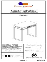
GRID
INSTALLATION
ESD BENCHTOP
GROUNDING
INSTRUCTIONS
Rear of Upright
GRID AND ACCESSORIES
GRID
ACCESSORIES
22" BIN
HOLDER
11" BIN
HOLDER
CATALOG/
FILE
HOLDER
UTILITY
RACK
GRID
SHELF
MONITOR
SHELF
WIRE
BASKET
Attach bin holders by first sliding top corner tabs up
behind a horizontal grid rod, then press bin holder
against the grid and slide down until the bottom corner
tabs are behind the next horizontal grid rod down.
WORKBENCH
SYSTEM
Assembly Instructions
MODEL NO. DESCRIPTION
MSB3060C 30 x 60, ESD
MSB3060L 30 x 60, Non-ESD
MSB3072C 30 x 72, ESD
MSB3072L 30 x 72, Non-ESD
MSB3660C 36 x 60, ESD
MSB3660L 36 x 60, Non-ESD
MSB3672C 36 x 72, ESD
MSB3672L 36 x 72, Non-ESD
InterMetro Industries Corporation
North Washington Street
Wilkes-Barre, PA 18705
For Product Information, Call (800) 433-2232
Visit Our Web Site: www.metro.com
L01-338
Rev. B
8/08
Information and specifications are subject to change
without notice. Please confirm at time of order.
Attach wire grid according to your
requirements. Typically, it’s a good idea
to install top of wire grid 12"-18" from top
of uprights.
Page 4

I. EXPLODED VIEW — PARTS AND ACCESSORIES GUIDE
Weight Capacities
Work Surfaces
1,000 lb. (453kg) evenly distributed
Cantilevered Shelves
100 lb. (45kg) evenly distributed weight
MSA-SMH Monitor Holder
45 lb. (21kg) evenly distributed weight
PBA-MS Monitor Shelf
50 lb. (23kg) evenly distributed weight
6" Drawer 12" Drawer
30 lb. (14kg) 40 lb. (18.4kg)
MSA-SBH Bin Panel Holder
50 lb. (23kg) evenly distributed weight
Electrical
Specications
LIGHT (MSA-LA60/MSA-LA72)
• UL Listing Pending
• Accepts two 48" (122cm) 40WT8
• fluorescent bulbs (not included)
• 7 foot cord
POWER STRIP
(MSA-PS60/MSA-PS72)
• 8 outlets
• 115V, 15A, 60Hz continuous service
• Includes ON
/OFF switch
• Protected by 15A circuit breaker
• 8 foot cord
12
17
18
13
11
14
15
16
19
60" 72"
KEY MODEL NO. MODEL NO. DESCRIPTION
1 MSA-LA60 MSA-LA72 Light Fixture with Mounting Arms
2 MSA-WS60 MSA-WS72 Cantilevered Shelf — Wire
3 MSA-LAM60 MSA-LAM72 Cantilevered Shelf — Laminate
4 MSA-BR60 MSA-BR72 Bin Rail
5 MSA-SDL6 MSA-SDL6 6" Drawer, Locking, Starter
6 MSA-SDL12 MSA-SDL12 12" Drawer, Locking, Starter
7 MSA-ADL6 MSA-ADL6 6" Drawer, Locking, Add-on
8 MSA-ADL12 MSA-ADL12 12" Drawer, Locking, Add-on
9 MSA-WG60 MSA-WG72 Wire Grid
10 PBA-MS PBA-MS Monitor Shelf
11 PBA-CHD PBA-CHD Catalog/File Holder
12 PBA-GSD PBA-GSD Grid Shelf
13 R24BR R24BR Utility Rack
14 H209C H209C Wire Basket
15 H210C H210C Wire Basket
60" 72"
KEY MODEL NO. MODEL NO. DESCRIPTION
16 H212C H212C Wire Basket
17 PBA-1BH PBA-1BH 11" Bin Holder
18 PBA-2BH PBA-2BH 22" Bin Holder
19 PBA-PFH PBA-PFH Hanging File Folder
20 MSA-PS60 MSA-PS72 Power Strip
21 MSA-FR60 MSA-FR72 Foot Rest
22 MSA-MARMS MSA-MARMS Overhead Mounting Arms
23 MSA-UR60 MSA-UR60 Uprights
24 MSA-TSH MSA-TSH Tool Storage Hanger
25 MSA-SSH MSA-SSH Solder Spool Holder
26 MSA-TT60 MSATT72 Tool Track and Trolley
27 MSA-SMH MSA-SMH Swing-Arm Monitor Holder
28 MSA-SBH MSA-SBH Swing-Arm Bin Panel Holder
29 MSA-LE MSA-LE Leg Extenders (4)
AVAILABLE ACCESSORIES
10
5
6 7 8
9
23
1
28
3
26
20
24
25
4
21
29
5
6
22
27
2
MOUNTING CHANNELS INCLUDED
WITH AND ONLY
OPTIONAL LEG EXTENDER INSTALLATION
ASSEMBLY TIP: Two (2) Allen wrenches are provided for bench assembly. However, a Ball-Socket Allen wrench will
shorten assembly time should you have access to one.
Page 1

II. BASIC WORKBENCH ASSEMBLY
1. Open cartons and identify the two leg assemblies
(A & B) and rails (C & D).
NOTE: Rear right and left legs of bench will have
pre-drilled hole for upright plate attachment (I) shown
below. Top side of rail will have pre-drilled holes for
mounting top.
2. Locate top of leg assemblies (A & B) and attach
rails (C & D) to legs with bracket (E) hardware and
Allen wrench provided.
3. Install foot inserts to bottom of legs by placing them
over the legs and tapping them into position with a
mallet. If optional leg extenders are being installed,
refer to diagram on opposite page.
4. Screw the leveling legs into the inserts and adjust
so that table is level.
5. If installing a grounding cable to the table top, it
must be attached to the underside of the top prior to
installing the top. See grounding diagram on page 4.
6. Position the table top (G) so that the rear of the top
is flush with the back of the table frame and has
equal overhang on both ends. Top must be flush
with back of the table, otherwise it may interfere with
upright mounting (shown below).
7. Attach the top to the frame by inserting the wood
screws (H) through the holes in the frame assembly
and screwing them into the underside of the top (G)
in eight places.
8. Make certain all bolts are securely tightened.
1. Open carton and identify the drawer mounting
channels and mounting hardware.
2. Install the mounting channels (K) on the underside
of the table frame; make sure that the short vertical
leg of the channel is to the inside of the drawer
on both channels. Tighten the hardware securely.
3. Remove the drawer (M) from the drawer frame (L)
by extending the drawer on its slides and then
flipping the slide safety stop downward to allow the
drawer to be disengaged from the frame.
4. Position the drawer frame (L) below the mounting
channels (K) and mount to the channels using the
hardware provided. Tighten the hardware securely.
5. Attach drawer front, handle and lock to drawer.
6. Reinstall the drawer to the drawer frame.
7. To install optional add-on drawers (N), remove
drawers from frames. Bolt frames together in
four places using the hardware provided with the
add-on drawer.
1. Orient the mounting brackets (I) so that the short flange is facing inward
(toward the table leg) and the long flange facing away from the table.
2. Attach the bracket to the table leg with the long bolt, washer, and nut.
3. Position the upright (J) against the mounting bracket and attach to the
bracket using the short bolt and rectangular nut. Follow the upright
accessory mounting instruction shown at the top of page 3.
4. The upright should always be attached using two bolts and at minimum,
it should be flush with the bottom of the bracket or protrude below.
(See overleaf for instructions on installation of upright mounted accessories.)
LONG
FLANGE
UPRIGHT
MOUNTING
PLATE
OPTION: ATTACH DRAWER ASSEMBLY
UPRIGHT MOUNTING INSTRUCTIONS
A
E
D
D
B
C
A
F
G
H
I
J
L
N
K
L
K
M
Page 2

1. With the exception of the wire shelf (see below), all
accessories that mount directly to the uprights are
attached in the same manner. Locate the Allen head
bolts and the rectangular nuts that are provided with
each accessory.
2. Insert the bolts through the mounting flange of
the accessory and attach the nuts to the bolts by
threading them on just a few threads. Make certain
that you thread the bolts into the nuts on the side of
the nut that has the double-serrated grooves on either
side of the threaded hole.
TYPICAL INSTALLATION FOR
UPRIGHT MOUNTED ACCESSORIES
1. Install the light support arms per instructions for upright mounted accessories (shown at top of page).
2. Position the light fixture below the support arms and attach to the
brackets following the same process as the assembly
of upright mounted accessories.
NOTE: If tool track
accessory is also to be mounted from support arms,
position front of light fixture at least 4" in on either side
of support arms.
3. To install bulbs, remove the two light diffuser
positioning screws from the front underside of the
light fixture. The screws are located approximately
1
/
3
of the way in from the end of the fixture.
4. To expose the bulb socket, slide the light diffuser forward
to allow the diffuser to drop out of the fixture at the rear.
5. Install the bulbs; replace the diffuser and reinstall the screws.
OVERHEAD LIGHT
BULBS NOT
INCLUDED
1. Determine whether the wire shelf will be installed
horizontally or pitched (see below).
1. Install the tubular shelf
supports per the
instructions above
for upright mounted
accessories.
2. Position the laminate
shelf on top of the
supports; attach the
shelf to the supports
by inserting the wood
screws through the
holes in the tubular
supports and screw-
ing them into the
underside of the
laminate shelf.
LAMINATE SHELFWIRE SHELF
TWO (2) 48" 40 WATT T8
FLUORESCENT BULBS REQUIRED.
3. Position the accessory on the upright in the desired location. Orient the rectangular nuts vertically so that
they will fit into the slot in the upright. Insert the Allen wrench into the nut and begin to tighten the bolt.
Make certain that the nut rotates a full 90° behind the anges of the upright. Check that the accessory
is at the desired position before tightening the bolt completely.
Page 3
2. Position the mounting
brackets in the desired
orientation and assemble
with the rectangular
nuts as shown above,
also using the Philips
head screws and flat
washers included in the
hardware bag.
NOTE: The short flanges
of the mounting brackets
should face inward when
properly installed.
3. Position the shelf on
the mounting brackets
and attach by inserting
two screws at each end
through the shelf and
threading into the bracket.
There are three narrowly-
spaced wires running front-to-back on the shelf; the
screws should go between the first and second wires
(starting from the outside edge of the shelf).
pitched
horizontal
/