Page is loading ...

1
vvvvbt
003-2417-00 Rev.B
Artizan
®
WallHungCabinetInstallation/UserManual
Applies to Models:
WHRS5400L/R
WHRS5800L/R
Modular Cabinets
Special Tools:
Level
Power Drill
3/4” Drill Bit
Language of origin: English
Note:
If applicable, Midmark casework unit must be connected to a dedicated
circuit with disconnect rated at 20A, 115V~, 60HZ. Failure to comply
could result in an overload of the electrical circuit and/or components.
All wiring, including disconnect, and plumbing must be installed by a
licensed electrician or plumbing contractor following applicable local, city,
and national codes.
Equipment Alert
Inspect all components for shipping damages. A concealed damage
report must be filed with the carrier (by the person receiving the
goods) within 15 days of delivery.
GA1144
WHRS5800R
GA1143
WHRS5400L
NextNext
BackBack

2
Equipment Alert
Indicates a potentially hazardous situation which
could result in equipment damage if not avoided.
Caution
Indicates a potentially hazardous situation which may
result in minor or moderate injury if not avoided. It
may also be used to alert against unsafe practices
WARNING
Indicates a potentially hazardous situation which
could result in serious injury if not avoided.
Important Information and Symbols
These symbols may appear on your equipment and / or in the manuals.
Note:
Amplifies a procedure, practice or condition.
Intended Use
The Midmark Artizan wall hung line of cabinetry is designed to be used as a
storage unit and workstation inside the healthcare office environment.
41 F
5 C 38 C
100 F
Proper Shipping Orientation
Fragile
Keep Dry
Consult User Guide
AC (Alternating Current)
Pressure Limits
Humidity Limit
Temperature Limit
Type B Applied Part
No Stacking
Corrugated Recycle
Disposal of Equipment / Consumable Goods
At the end of this products life, the unit, accessories and other consumable goods may
be contaminated from normal use. Consult local codes and
ordinates for proper disposal of this equipment and other consumables.
• Approved for indoor use only.
Transportation / Storage / Operating Conditions
Transportation / Storage Temperature Range: ..0°F to 140°F (-18°C to 60°C)
Relative Humidity:...............................................10% to 90% (Non-Condensing)
Atmospheric Pressure:.......................................7.2 PSI to 15.3 PSI (50 kPa to 106 kPa)
Operating Temperature Range...........................59°F to 95°F (15°C to 35°C)
Specications
~
Contact Information:
Midmark Corporation
115 G.L. Comer Road
Glasgow, Kentucky 42141
Phone: 1-800-643-6275 ext. 88015
Fax: (270)-651-1732
NextNext
BackBack

3
Wall Layout (WHRS5400)
Note:
Have licensed electrical and plumbing
contractors position and install electrical
outlet receptacles and related plumbing
using the pre-installation template or layout.
Assure wall is of such construction that
the unit will be adequately supported and
anchored. If necessary contact a licensed
contractor to reinforce the wall.
GA1159
Note:
A full size, pre-installation floor template is available
upon request:
• WHRS5400L, P/N: 003-2418-00
• WHRS5400R, P/N: 003-2418-01
GA1155
GA1156
WHRS5400L
WHRS5400R
NextNext
BackBack

4
Wall Layout (WHRS5800)
Note:
Have licensed electrical and
plumbing contractors position and
install electrical outlet receptacles and
related plumbing using the
pre-installation template or layout.
Assure wall is of such construction that
the unit will be adequately supported
and anchored. If necessary contact
a licensed contractor to reinforce the
wall.
Note:
A full size, pre-installation floor template is available
upon request:
• WHRS5800L, P/N: 003-2419-00
• WHRS5800R, P/N: 003-2419-01
GA1159
GA1157
GA1158
WHRS5800L
WHRS5800R
NextNext
BackBack

5
Step 1: Remove the cabinets from shipping pallet
A) Cut straps and remove shipping materials.
B) Remove cabinet drawers and doors (see Drawer Removal,
Installation, and Adjustment in this manual).
Wall Hung Installation
WARNING
Cabinet weighs 125-150 pounds. Remove the doors
and drawers to make the cabinet lighter and to keep
them from coming open during installation. Lift with two
people on the bottom edge of the cabinet from both ends.
GA1148
NextNext
BackBack

6
Wall Hung Installation
GA1149
Screws
Toggle
Bolts
Step 2: Installing the Hang Rail
A) Determine the final desired height of the countertop
and subtract 3-3/4”. Make a level line on the wall at this
height for later reference. (33” operatory cabinet = 29-
1/4” to line from the finished floor.)
B) Mark intersecting studs on level line.
C) Using the hang rail as a template, line up the rail holes
with the stud marks made in step B and mark the wall
for anchor locations every 8 inches between studs
making sure the anchors will line up with the holes in
the hang rail.
D) Install the provided anchors in 16” increments between
the studs in the marked locations. (See Anchor Instal-
lation)
E) Using the provided lag screws attach the hang rail to
the wall.
F) Using 2-1/2” drywall screws (for wood studs), attach
the rail to studs in 16” increments. (For metal studs see
note)
Note:
If metal studs were used in the construction of the walls, use a
1-1/2” LG fine thread flanged screw with a head no smaller than 5/16”
diameter
WARNING
The ends of the hang rail must be fastened to the wall
with either a toggle bolt and anchor (if in-between studs)
or a screw (if on stud).
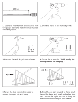
Anchor Installation
A) Drill holes using a 1/2” drill bit through drywall in the specified locations.
B) Hold the metal channel flat alongside the plastic straps with the top of the
channel facing up and slide through the hole drilled in step A.
C) Hold the ends of the straps between thumb and forefinger and pull toward
you until channel rests flush behind wall. slide plastic cap along straps with other
hand until flange of cap is flush with wall.
D) Snap straps at the wall by pushing side to side. Repeat at each location.
Note:
Minimum clearance behind wall: 1-7/8”.
WARNING
The hang rail must be fastened on the ends and every
8”. Attachments are between studs with the provided an-
chors on 16” increments and must also be attached to a stud every
16” to support the rated load of 20 pounds per foot. (approx. 100
pounds for a WHRS5400 and WHRS5800) See diagram below.
NextNext
BackBack

7
Wall Hung Installation
Step 3: Hanging the Cabinets
A) Adjust the cabinet hangers to the extended position
in each cabinet. (See Hang Block Adjustments in
this manual)
B) Lift the cabinets from both ends keeping the
cabinets in the upright orientation.
C) Move the cabinets to the wall and lower the
cabinets so the hangers catch on the hang rail. Be
sure not to scratch the wall when lowering the
cabinets onto the rail.
D) Verify that all the hangers are hooked on the rail
before adjusting the hangers. (See Hang Block
Adjustments in this manual)
E) Adjust all the hangers in each cabinet evenly until
1/16” gap is between the cabinet and the wall.
F) Using a level, adjust the hangers evenly across the
cabinets as necessary to level the cabinet. (See
Hang Block Adjustments in this manual)
G) Tighten hangers so cabinet is tight against the wall.
(See Hang Block Adjustments in this manual)
Caution
Verify that all the hangers are hooked on the rail
before fully retracting the hangers. (See Hang Block
Adjustments in this manual)
Equipment Alert
Adjusting both ends of the assembly will level the
cabinets but will not support the rated load. Be sure that all the
Hang Blocks are adjusted vertically such that they are supporting
the load of the cabinets. (Two hang blocks per cabinet)
GA1151
1
2
Hang Block Adjustments
1) Loosen the lower screw on the hanger adjustment block to
extend the hanger outward equally beyond the back of the
cabinet. (Clockwise retracts and counterclockwise extends the
hanger.)
2) The top screw is used for vertical adjustment. Do not over
tighten. (Clockwise raises the cabinet and counterclockwise
lowers the cabinet.)
NextNext
BackBack

8
Wall Hung Installation
Step 4: Hanging Counter top supports (if applicable)
A) Adjust the support hangers to the extended position
in each cabinet. (See Hang Block Adjustments in this
manual)
B) Place the support on the hang rail and adjust the hangers
evenly so there is a 1/16” gap between the support and the
wall.
C) Adjust the support so that it is level with other cabinets
hanging on the rail.
D) Mark the anchor locations on the wall through the pilot holes
in the counter top support.
E) Remove the countertop support and install the anchors in
the wall. (see Anchor Installation in this manual)
F) Place the support back on the rail and tighten the hangers
so the support is against the wall.
G) Use the provided toggle bolts to fasten the support to the
anchors in the wall.
Caution
Verify that all the hangers are hooked on the rail
before fully retracting the hangers. (See Hang Block
Adjustments in this manual)
Equipment Alert
Adjusting both ends of the assembly will level the
cabinets but will not support the rated load. Be sure that all the
Hang Blocks are adjusted vertically such that they are supporting
the load of the cabinets. (Two hang blocks per cabinet)
GA1160
NextNext
BackBack

9
Wall Hung Installation
Step 5: Install Countertop
A) Remove packaging from shipping container and place the
countertop on the wall hung cabinet.
B) Adjust the countertop against the wall and overhanging the side
of the cabinet by a 1/2” on either side.
C) In general, use the supplied 1” drywall screws to fasten L-brackets
to the countertop and 1-5/8” screws through pre-drilled holes in the
tops of all other cabinets.
GA1150
1” Drywall
Screws
1-5/8” Drywall
Screws
NextNext
BackBack

10
GA1153
Step 6: Doors and Drawers
A) Re-install cabinet drawers (see Drawer
Removal, Installation, and Adjustment in this manual)
and make adjustments as needed.
B) Re-install cabinet doors (see Door Removal, Installation,
and Adjustment in this manual) and make adjustments
as needed.
Equipment Alert
Maximum recommended weight for contents in drawers is 5 pounds for
medium (3.15” HGT) drawer boxes and 10 pounds for large (5.9” HGT)
drawer boxes.
Wall Hung Installation
NextNext
BackBack

11
Drawer Installation
A) Fully extend drawer glides from the cabinet. (Optional)
B) Place the drawer on the glides.
C) Push the drawer in completely.
D) Cycle drawer a couple times to ensure that the drawer is
securely attached to the glides.
Drawer Removal
A) Open drawer completely.
B) Lift up on the drawer front until the front of the box releases from the glide.
C) Pull out on the drawer slightly.
D) Lower the drawer back down while pulling out on the drawer.
Drawer Front Adjustment and Removal
1) Remove the cover caps on the drawer side by hand.
2) Height Adjustment: Rotate in either direction to adjust the drawer front vertically.
3) Tilt Adjustment: Adjust after the drawer front is installed to ensure the drawer sides meet
square with the drawer front. (Only available on large drawer boxes.)
4) Side Adjustment: Adjusts the drawer front horizontally. Turn in either direction.
5) Tension/Removal: For large drawers, turn the screw toward the front of the drawer until the
front detaches from the box. Repeat this procedure on both sides of the drawer. For small
and medium drawer boxes, turn the screw toward the back of the drawer to remove the
front.
Drawer Removal, Installation and Adjustment
Removal
A) Extend the glide to its outermost position.
Push the release levers in and remove the
drawer member of the sides.
Full Extension Glide Removal & Installation...
PUSH
PULL
Cabinet Member
Drawer Member
Installation
A) Line up the drawer member to the cabinet
member and push the drawer into its
compartment.
A
B
C
D
GA1106
GA1107
4
5
32
GA1105
NextNext
BackBack

12
A
B
C
Hinge 1 & 2 Adjustment
Direction Guide
Hinge 1 & 2 Adjustments
Use a phillips head screw driver for the following steps...
A) Screw A adjusts the door in direction A seen in the
Adjustment Direction Guide
B) Screw B adjusts the door in direction B. Equal
adjustment must be made to all hinges on the door for it
to move the desired distance.
C) Screw C adjusts the door in the C direction. Make
adjustments to top and bottom hinge as necessary.
Note: Use a level to ensure the door is level and plumb. Preferred gaps are
approximately 1/8” between doors and 1/16” between accents and doors.
180° Hinge Adjustments
D) Loosen screw D and adjust door gap
and angle using a level. Tighten screw D
when positioned correctly,
180° Hinge
D
Hinge 1 & 2 Removal
E) Press button at point E at the back of
the hinge and pull away from cabinet.
Door Removal, Installation, and Adjustment
B
C
A
Hinge 1
E
Hinge 1 & 2 Installation
F) Hook the hinge to the mounting block at
point F
G) Latch at point G by pressing the hinge
against the hinge block.
F
G
Hinge 2
A
B
C
E
GA1044
NextNext
BackBack

13
Disinfecting Procedures for External Surfaces
Attention!
Midmark assumes no responsibility or liability for any result, expressed or implied.
These are suggested practices, based on the best information available at this time.
When using disinfectants...
Carefully read the product label and directions for use.
Do not exceed the dilution rate.
Read all labels carefully!
Cleaning and Disinfectant Procedures
Use cleaners and disinfectants that are appropriate for the situation such as warm water and mild detergents, or an ammonia based cleaner.
NOTE: Every dental practice is different, and no single disinfectant is the best choice for every facility. Listed below are some organizations to assist you in choosing the best disinfectants
available for your practice.
• Organization for Safety & Asepsis Procedures: http://www.osap.org
• American Dental Association: http://www.ada.org
• Dept. of Health & Human Resources Centers for Disease Control & Prevention (CDC):
http://www.cdc.gov
Equipment Alert
• Users should not use cleaning or decontamination methods different from those recommended by the manufacturer without first checking with the manufacturer that the
proposed methods will not damage the equipment.
• Midmark’s dental equipment is manufactured from the most chemical-resistant materials available. However, no material is impervious to every chemical. Using protective
barriers is the most effective method to prevent equipment damage.
• Use only moist cloth with appropriate cleaner for cleaning casework.
Cleaning / Maintenance (Casework)
NextNext
BackBack

14
Caring for your Solid Surface countertop is as simple as wiping the surface with a damp cloth. If a stain develops, wipe it away with soap and water. Or if you prefer wipe it clean with ammo-
nia based cleaner.
If a stain doesn’t respond to soap and water, for a matte nish, apply an abrasive cleanser and buff with a Scotch-Brite pad using a circular motion. The same technique can be used for
burns. If you have a gloss nish, please contact your dealer or fabricator before attempting repairs.
For minor cuts and scratches, simply sand lightly with a medium (220 grit) sandpaper, then follow with a ne (320 grit) sandpaper. Finally, touch up the nish by bufng with a Scotch-Brite
TM
pad.
Caution
Do not expose the surface to harsh chemicals, such as paint remover,
turpentine, nail polish remover or stove and drain cleaners. If these
chemicals come in contact with the surface, immediately wash them off with water,
using appropriate safety measures to avoid injury.
Cleaning and Maintenance (Solid Surface)
NextNext
BackBack
Midmark Corporation
For additional contact information, go to:
www.midmark.com
/