Page is loading ...

Display
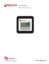
ER-500 Advanced
DSY-PM-00028-EN-02 (February 2017)
Programming Manual

ER-500 Flow Monitor
Page ii February 2017DSY-PM-00028-EN-02

CONTENTS
Scope of This Manual . . . . . . . . . . . . . . . . . . . . . . . . . . . . . . . . . . . . . . . . . . . . . . . . . . . . . . . . . . . . . . . . . . . 5
Unpacking and Inspection . . . . . . . . . . . . . . . . . . . . . . . . . . . . . . . . . . . . . . . . . . . . . . . . . . . . . . . . . . . . . . . 5
Safety . . . . . . . . . . . . . . . . . . . . . . . . . . . . . . . . . . . . . . . . . . . . . . . . . . . . . . . . . . . . . . . . . . . . . . . . . . . . . 5
Terminology and Symbols . . . . . . . . . . . . . . . . . . . . . . . . . . . . . . . . . . . . . . . . . . . . . . . . . . . . . . . . . . . . . 5
Considerations . . . . . . . . . . . . . . . . . . . . . . . . . . . . . . . . . . . . . . . . . . . . . . . . . . . . . . . . . . . . . . . . . . . . 5
Electrical Symbols . . . . . . . . . . . . . . . . . . . . . . . . . . . . . . . . . . . . . . . . . . . . . . . . . . . . . . . . . . . . . . . . . . 5
Introduction. . . . . . . . . . . . . . . . . . . . . . . . . . . . . . . . . . . . . . . . . . . . . . . . . . . . . . . . . . . . . . . . . . . . . . . . . 6
Installation. . . . . . . . . . . . . . . . . . . . . . . . . . . . . . . . . . . . . . . . . . . . . . . . . . . . . . . . . . . . . . . . . . . . . . . . . . 7
Connecting the ER-500 Monitor to a Pulse Output Device. . . . . . . . . . . . . . . . . . . . . . . . . . . . . . . . . . . . . . . . . 7
Transmitter Connections . . . . . . . . . . . . . . . . . . . . . . . . . . . . . . . . . . . . . . . . . . . . . . . . . . . . . . . . . . . . . . 7
Power Connections . . . . . . . . . . . . . . . . . . . . . . . . . . . . . . . . . . . . . . . . . . . . . . . . . . . . . . . . . . . . . . . . . 8
Operating The Monitor . . . . . . . . . . . . . . . . . . . . . . . . . . . . . . . . . . . . . . . . . . . . . . . . . . . . . . . . . . . . . . . . . . 9
Buttons . . . . . . . . . . . . . . . . . . . . . . . . . . . . . . . . . . . . . . . . . . . . . . . . . . . . . . . . . . . . . . . . . . . . . . . . . 9
Special Functions . . . . . . . . . . . . . . . . . . . . . . . . . . . . . . . . . . . . . . . . . . . . . . . . . . . . . . . . . . . . . . . . . . 9
Modes. . . . . . . . . . . . . . . . . . . . . . . . . . . . . . . . . . . . . . . . . . . . . . . . . . . . . . . . . . . . . . . . . . . . . . . . . . 9
Programming Using Frequency Output Flow Sensors . . . . . . . . . . . . . . . . . . . . . . . . . . . . . . . . . . . . . . . . . . . 9
Menu Structure. . . . . . . . . . . . . . . . . . . . . . . . . . . . . . . . . . . . . . . . . . . . . . . . . . . . . . . . . . . . . . . . . . . . . . 10
Standard ER-500, Rate SU is Set to Simple . . . . . . . . . . . . . . . . . . . . . . . . . . . . . . . . . . . . . . . . . . . . . . . . . . 10
Advanced ER-500, Basic Menu . . . . . . . . . . . . . . . . . . . . . . . . . . . . . . . . . . . . . . . . . . . . . . . . . . . . . . . . . 11
Standard ER-500, Rate SU is Set to Advanced . . . . . . . . . . . . . . . . . . . . . . . . . . . . . . . . . . . . . . . . . . . . . . . . 12
Advanced ER-500, Advanced Menu . . . . . . . . . . . . . . . . . . . . . . . . . . . . . . . . . . . . . . . . . . . . . . . . . . . . . . 14
Programming. . . . . . . . . . . . . . . . . . . . . . . . . . . . . . . . . . . . . . . . . . . . . . . . . . . . . . . . . . . . . . . . . . . . . . . 16
Parameters. . . . . . . . . . . . . . . . . . . . . . . . . . . . . . . . . . . . . . . . . . . . . . . . . . . . . . . . . . . . . . . . . . . . . . 16
K-factors Explained . . . . . . . . . . . . . . . . . . . . . . . . . . . . . . . . . . . . . . . . . . . . . . . . . . . . . . . . . . . . . . . . . . . 25
Modbus Interface . . . . . . . . . . . . . . . . . . . . . . . . . . . . . . . . . . . . . . . . . . . . . . . . . . . . . . . . . . . . . . . . . . . . 27
Modbus Register / Word Ordering . . . . . . . . . . . . . . . . . . . . . . . . . . . . . . . . . . . . . . . . . . . . . . . . . . . . . . . 27
Register Mappings. . . . . . . . . . . . . . . . . . . . . . . . . . . . . . . . . . . . . . . . . . . . . . . . . . . . . . . . . . . . . . . . . 27
Battery Replacement . . . . . . . . . . . . . . . . . . . . . . . . . . . . . . . . . . . . . . . . . . . . . . . . . . . . . . . . . . . . . . . . . . 29
Specications. . . . . . . . . . . . . . . . . . . . . . . . . . . . . . . . . . . . . . . . . . . . . . . . . . . . . . . . . . . . . . . . . . . . . . . 30
Model Numbers . . . . . . . . . . . . . . . . . . . . . . . . . . . . . . . . . . . . . . . . . . . . . . . . . . . . . . . . . . . . . . . . . . . . . 31
Dimensions . . . . . . . . . . . . . . . . . . . . . . . . . . . . . . . . . . . . . . . . . . . . . . . . . . . . . . . . . . . . . . . . . . . . . . . . 31
Troubleshooting Guide. . . . . . . . . . . . . . . . . . . . . . . . . . . . . . . . . . . . . . . . . . . . . . . . . . . . . . . . . . . . . . . . . 31
Control Drawing . . . . . . . . . . . . . . . . . . . . . . . . . . . . . . . . . . . . . . . . . . . . . . . . . . . . . . . . . . . . . . . . . . . . . 32
Programming Manual
Page iii February 2017 DSY-PM-00028-EN-02

ER-500 Flow Monitor
Page iv February 2017DSY-PM-00028-EN-02

SCOPE OF THIS MANUAL
This manual is intended to help you get the ER-500 flow monitor up and running quickly.
MPORTANTI
Read this manual carefully before attempting any installation or operation. Keep the manual accessible for future reference.
UNPACKING AND INSPECTION
Upon opening the shipping container, visually inspect the product and applicable accessories for any physical damage such
as scratches, loose or broken parts, or any other sign of damage that may have occurred during shipment.
OTE:N If damage is found, request an inspection by the carrier’s agent within 48 hours of delivery and file a claim with the
carrier. A claim for equipment damage in transit is the sole responsibility of the purchaser.
SAFETY
Terminology and Symbols
Indicates a hazardous situation, which, if not avoided, is estimated to be capable of causing death or
serious personal injury.
Indicates a hazardous situation, which, if not avoided, could result in severe personal injury or death.
Indicates a hazardous situation, which, if not avoided, is estimated to be capable of causing minor or
moderate personal injury or damage to property.
Considerations
The installation of the ER-500 flow monitor must comply with all applicable federal, state, and local rules, regulations,
and codes.
WARNING
EXPLOSION HAZARD - SUBSTITUTION OF COMPONENTS MAY IMPAIR SUITABILITY FOR CLASS I, DIVISION 2.
AVERTISSMENT
RISQUE D’EXPLOSION - LA SUBSTITUTION DE COMPOSANTS PEUT RENDRE CEMATÉRIEL INACCCEPTABLE POUR LES
EMPLACEMENTS DE CLASSE I, DIVISION 2.
WARNING
DO NOT CONNECT OR DISCONNECT EITHER POWER OR OUTPUTS UNLESS THE AREA IS KNOWN TO BE
NON-HAZARDOUS.
AVERTISSMENT
RISQUE D’EXPLOSION. NE PAS DÉBRANCHER TANT QUE LE CIRCUIT EST SOUSTENSION, À MOINS QU’LL NE S’AGISSE
D’UN EMPLACEMENT NON DANGEREUX.
MPORTANTI
Not following instructions properly may impair safety of equipment and/or personnel.
Electrical Symbols
Function Direct Current Alternating Current Earth (Ground) Protective Ground Chassis Ground
Symbol
Scope of This Manual
DSY-PM-00028-EN-02 Page 5 February 2017

INTRODUCTION
The ER-500 flow monitor incorporates state-of-the-art digital signal processing technology designed to provide the user with
exceptional flexibility at a very affordable price. Though designed for use with Badger Meter® flow sensors, this monitor can
be used with almost any flow sensor producing a low amplitude AC output or contact closure signal.
The ER-500 monitor uses contact closures from an ILR transmitter that translates to flow rate through the use of a scaling
constant called a K-factor.
This monitor is also capable of accepting low-level frequency input signals typically found in flow sensors that generate
a frequency output. The output signal for these type of sensors is a frequency proportional to the rate of flow. The ER-500
monitor uses the frequency information to calculate flow rate and total flow. If required, the flow monitor can easily be
re-configured in the field.
Freq. In
4-20mA
Iso Total Pluse
TR_B
TR_A
RS485 Gnd
Setpoint 1
Setpoint 2
Gnd
+
–
+
–
+
–
Total Reset
OC Total Pluse
Signal Gnd
+ –
KB/Display
J1
TB1
JP1
JP2
JP3
P2
Input Total Pulse Signal
P1
Mag
Pulse
Iso
OC
Low
High
2
1
Figure 1: ER-500 monitor
The monitor is available in two different levels of functionality. The standard model provides all the functions necessary for
the most common flow metering applications. The advanced version adds communications capabilities over an RS485 bus
using Modbus RTU and control outputs.
Introduction
DSY-PM-00028-EN-02Page 6 February 2017

INSTALLATION
Connecting the ER-500 Monitor to a Pulse Output Device
The ER-500 monitor has two jumpers that are used to set the type of signal and the minimum amplitude of the signal that
it accepts. When used with Badger Meter IOG oval gear meters, the Input Signal Level should be set to Low and the Input
Waveform should be set for pulse as shown in Figure 2.
JP1
JP2
JP3
Input Total Pulse Signal
Mag
Pulse
Iso
OC
Low
High
Input Waveform Selection
(Should be set to Pulse for IOG meter)
Input Signal Level Selection
(Should be set to Low for IOG Meter)
Figure 2: Input jumper settings
If the ER-500 monitor is a replacement, it must be calibrated for the IOG it is intended to be used with. The K-factor for the
specific IOG meter must be programmed into the ER-500 monitor. The K-factor value is found on the calibration certificate
that came with the IOG meter. For instructions on programming the K-factor, see Enter Flow Sensor's K-factor* on page 17.
Transmitter Connections
The ILR transmitter typically used with the IOG meter family has two sets of pulse output wires. The white and green output
leads connected to the primary reed switch bank are generally the first choice (see Figure 3).
JP1
JP2
JP3
Input Total Pulse Signal
P1
Freq. In
4-20mA
Iso Total Pluse
TR_B
TR_A
RS485 Gnd
Setpoint 1
Setpoint 2
Gnd
+
–
+
–
+
–
Total Reset
OC Total Pluse
Signal Gnd
TB1
Mag
Pulse
Iso
OC
Low
High
Freq. In
Gnd
Mag
Pulse
+
–
Reed Switch
Bank
ILR
Pulse Transmitter
White
Green
Blue
Black
Auxiliary Reed
Switch Bank
Figure 3: Typical IOG meter input connection
The ILR transmitter also has a secondary (auxiliary) set of pulse output wires. Either pair can be used to connect to the ER-500
monitor. The connections are:
ILR Wires
ER-500 Terminals Reed Switch Bank (Primary) Reed Switch Bank (Auxiliary)
Freq. In + White Blue
Freq. In - Green Black
Installation
DSY-PM-00028-EN-02 Page 7 February 2017

Power Connections
The ER-500 monitor has two power supply options. The first power supply is an internal lithium 3.6V DC D size cell that powers
the monitor for about six years when no outputs are used. The monitor can also be powered by a 4…20 mA current loop.
See Figure 4. If the current loop is used, a sensing circuit within the monitor detects the presence of the current loop and
automatically disconnects the battery from the circuit.
JP1
JP2
JP3
Input Total Pulse Signal
P1
Freq. In
4-20mA
Iso Total Pluse
TR_B
TR_A
RS485 Gnd
Setpoint 1
Setpoint 2
Gnd
+
–
+
–
+
–
Total Reset
OC Total Pluse
Signal Gnd
TB1
Mag
Pulse
Iso
OC
Low
High
4-20 mA
Current Loop
(10 …28V DC)
Load
10
…28V DC
Figure 4: Loop power connections
Installation
DSY-PM-00028-EN-02Page 8 February 2017

OPERATING THE MONITOR
2
1
Figure 5: Keypad detail
Buttons
MENU Switches between RUN and PROGRAMMING modes
UP
Scrolls backwards through the parameter options, increments numeric variables and scrolls backward through
parameters
RIGHT
Scrolls forward through the parameter options, moves the active digit to the right and scrolls forward through
parameters
ENTER Saves programming information, advances to the next programming parameter, and used in the reset process
Special Functions
MENU + ENTER Simultaneously press and hold to reset the current totalizer
MENU Press and hold for three seconds to enter Extended Programming mode
UP+ RIGHT Simultaneously press and hold to show the firmware version number, then the grand total
Modes
RUN Normal operating mode
PROGRAM Used to program parameters in the display
EXTENDED PROGRAMMING Used to program advanced variables into the display
TEST Used as a diagnostic tool to show input frequency and totalizer counts
If the monitor is a replacement, the K-factor of the flow sensor has changed, or the monitor is being used with some other
pulse generating device, programming is necessary.
Programming Using Frequency Output Flow Sensors
Each Badger Meter flow sensor is shipped with either a K-factor value or frequency data. If frequency data is provided, the
data must be converted to a K-factor before programming the monitor. The K-factor represents the number of pulses per
unit of volume. See Connecting the ER-500 Monitor to a Pulse Output Device on page 7. The K-factor is needed to program
the monitor.
Operating The Monitor
DSY-PM-00028-EN-02 Page 9 February 2017

MENU STRUCTURE
Standard ER-500, Rate SU is Set to Simple
Numeric Entry
KFactor
(K-Factor Value)
KFacUnt
(K-Factor Unit)
START
Basic Menu
Extended Menu
Sub Menu
Pul/Gal
Pul/m³
Pul/Ltr
Pul/Ft³
=
=
=
=
Pulses/Gallon
Pulses/meter³
Pulses/Liter
Pulses/Ft³
Shape Key
Rate SU
(Rate Unit Setup)
Simple Advanced
Flo Unt
(Rate/Total Units)
GPM
Gal
OB/D
BBL
m³/D
m³
m³/H
m³
LPM
Ltr
=
=
=
=
=
=
=
=
=
=
Gallons/Min
Gallons
Oil Barrel/Day
Barrels
Meters³/Day
Meters³
Meters³/Hour
Meters³
Liters/Min
Liters
PulsOut
(Pulse Output)
Disable
Enable
Numeric Entry
Fl=20mA
(Flow at 20 mA)
Clr G-T
(Clear Grand Total)
NO
YES
Passwd
(Password)
Numeric Entry
RstPswd
(Reset Password)
Numeric Entry
Menu Structure
DSY-PM-00028-EN-02Page 10 February 2017

Advanced ER-500, Basic Menu
Numeric Entry
KFactor
(K-Factor Value)
KFacUnt
(K-Factor Unit)
START
Basic Menu
Extended Menu
Sub Menu
Pul/Gal
Pul/m³
Pul/Ltr
Pul/Ft³
=
=
=
=
Pulses/Gallon
Pulses/meter³
Pulses/Liter
Pulses/Ft³
Shape Key
=
=
=
=
Sec
Min
Hour
Day
Second
Minute
Hour
Day
RateInt
(Rate time interval)
MASS
RateUnt
(Unit/interval=T)
GPT
LB/T
OB/T
AF/T
ML/T
LPT
m³/T
Ft³/T
MG/T
Kg/T
Lb/T
=
=
=
=
=
=
=
=
=
=
=
Gallons/T
Liquor Barrel/T
Oil Barrel/T
Acre Feet/T
Million Liters/T
Liters/T
Meters³/T
Feet³/T
Million
Gallons/T
Kilograms/T
Pounds/T
MASS
TotalUnt
(Totalizer Unit)
Gal
LBL
OBL
AFt
MLt
LPT
m³
Ft³
MGa
Kgs
Lbs
=
=
=
=
=
=
=
=
=
=
=
Gallons
Liquor Barrel
Oil Barrel
Acre Feet
Million Liters
Liters
Meters³
Feet³
Million
Gallons
Kilograms
Pounds
Menu item appears
only when MASS
units are selected.
Spec Gr
(Specic Gravity)
TotlMult
(Totalizer Multiplier)
× 1000
× 100
× 10
× 1
× 0.1
× 0.01
=
=
=
=
=
=
×1000
×100
×10
1
0.1
0.01
Numeric Entry
PulsOut
(Pulse Output)
Disable
Enable
Numeric Entry
Fl=20mA
(Flow at 20 mA)
Clr G-T
(Clear Grand Total)
NO
YES
Passwd
(Password)
Numeric Entry
RstPswd
(Reset Password)
Numeric Entry
Menu Structure
DSY-PM-00028-EN-02 Page 11 February 2017

Standard ER-500, Rate SU is Set to Advanced
Numeric Entry
KFactor
(K-Factor Value)
KFacUnt
(K-Factor Unit)
START
Basic Menu
Extended Menu
Sub Menu
Pul/Gal
Pul/m³
Pul/Ltr
Pul/Ft³
=
=
=
=
Pulses/Gallon
Pulses/meter³
Pulses/Liter
Pulses/Ft³
Shape Key
Rate SU
(Rate Unit Setup)
Simple Advanced
Display (Options)
Flow
Flow GT = Grand Total
Test
=
=
=
=
Sec
Min
Hour
Day
Second
Minute
Hour
Day
RateInt
(Rate time interval)
MASS
RateUnt
(Unit/interval=T)
GPT
LB/T
OB/T
AF/T
ML/T
LPT
m³/T
Ft³/T
MG/T
Kg/T
Lb/T
=
=
=
=
=
=
=
=
=
=
=
Gallons/T
Liquor Barrel/T
Oil Barrel/T
Acre Feet/T
Million Liters/T
Liters/T
Meters³/T
Feet³/T
Million
Gallons/T
Kilograms/T
Pounds/T
MASS
TotalUnt
(Totalizer Unit)
Gal
LBL
OBL
AFt
MLt
LPT
m³
Ft³
MGa
Kgs
Lbs
=
=
=
=
=
=
=
=
=
=
=
Gallons
Liquor Barrel
Oil Barrel
Acre Feet
Million Liters
Liters
Meters³
Feet³
Million
Gallons
Kilograms
Pounds
Menu item appears
only when MASS
units are selected.
Continued on
next page.
Spec Gr
(Specic Gravity)
TotlMult
(Totalizer Multiplier)
× 1000
× 100
× 10
× 1
× 0.1
× 0.01
=
=
=
=
=
=
×1000
×100
×10
1
0.1
0.01
Numeric Entry
Scale F
(Scale Factor)
Numeric Entry
SetTotl
(Set Total Value)
Numeric Entry
Cuto
(Low Flow Cuto)
Numeric Entry
Damping
(Display Damping)
Numeric Entry
Menu Structure
DSY-PM-00028-EN-02Page 12 February 2017

Standard ER-500, Rate SU is Set to Advanced (continued)
4-20Cal
(Calibrate 4-20)
Lin Pts = Linear Points (2 to10)
Linear
(Linearization)
Freq#1
(Frequency 1)
Clr G-T
(Clear Grand Total)
NO
YES
4mA Out
(4 mA Output)
Numeric Entry
20mA Out
(20 mA Output)
Numeric Entry
4-20Tst
(4-20 mA Output)
Numeric Entry
Numeric Entry
Numeric Entry
Coef#1
(Coecient 1)
Numeric Entry
Freq#(x)
(Frequency 2-10)
Numeric Entry
Coef#(x)
(Coecent 2-10)
Numeric Entry
NO
YES
Passwd
(Password)
Numeric Entry
RstPswd
(Reset Password)
Numeric Entry
PulsOut
(Pulse Output)
Disable
Enable
Numeric Entry
Fl=20mA
(Flow at 20 mA)
Continued from
previous page.
Menu Structure
DSY-PM-00028-EN-02 Page 13 February 2017

Advanced ER-500, Advanced Menu
Numeric Entry
KFactor
(K-Factor Value)
START
Basic Menu
Extended Menu
Sub Menu
KFacUnt
(K-Factor Unit)
Pul/Gal
Pul/m³
Pul/Ltr
Pul/Ft³
=
=
=
=
Pulses/Gallon
Pulses/meter³
Pulses/Liter
Pulses/Ft³
Shape Key
Display (Options)
Flow
Flow GT = Grand Total
Test
=
=
=
=
Sec
Min
Hour
Day
Second
Minute
Hour
Day
RateInt
(Rate time interval)
MASS
RateUnt
(Unit/interval=T)
GPT
LB/T
OB/T
AF/T
ML/T
LPT
m³/T
Ft³/T
MG/T
Kg/T
Lb/T
=
=
=
=
=
=
=
=
=
=
=
Gallons/T
Liquor Barrel/T
Oil Barrel/T
Acre Feet/T
Million Liters/T
Liters/T
Meters³/T
Feet³/T
Million
Gallons/T
Kilograms/T
Pounds/T
MASS
TotalUnt
(Totalizer Unit)
Gal
LBL
OBL
AFt
MLt
LPT
m³
Ft³
MGa
Kgs
Lbs
=
=
=
=
=
=
=
=
=
=
=
Gallons
Liquor Barrel
Oil Barrel
Acre Feet
Million Liters
Liters
Meters³
Feet³
Million
Gallons
Kilograms
Pounds
Menu item appears
only when MASS
units are selected.
Continued on
next page.
Spec Gr
(Specic Gravity)
TotlMult
(Totalizer Multiplier)
× 1000
× 100
× 10
× 1
× 0.1
× 0.01
=
=
=
=
=
=
×1000
×100
×10
1
0.1
0.01
Numeric Entry
Scale F
(Scale Factor)
Numeric Entry
SetTotl
(Set Total Value)
Numeric Entry
Cuto
(Low Flow Cuto)
Numeric Entry
Damping
(Display Damping)
Numeric Entry
Menu Structure
DSY-PM-00028-EN-02Page 14 February 2017

Advanced ER-500, Advanced Menu (continued)
4-20Cal
(Calibrate 4-20)
Lin Pts = Linear Points (2 to10)
Linear
(Linearization)
Freq#1
(Frequency 1)
NO
YES
4mA Out
(4 mA Output)
Numeric Entry
20mA Out
(20 mA Output)
Numeric Entry
4-20Tst
(4-20 mA Output)
Numeric Entry
Numeric Entry
Numeric Entry
Coef#1
(Coecient 1)
Numeric Entry
Freq#(x)
(Frequency 2-10)
Numeric Entry
Coef#(x)
(Coecent 2-10)
Numeric Entry
PulsOut
(Pulse Output)
Disable
Enable
Numeric Entry
Fl=20mA
(Flow at 20 mA)
Continued from
previous page.
Modbus Address (1 to127)
BusAddr
Clr G-T
(Clear Grand Total)
Passwd
Password
Modbus
Disable
Enable
Numeric Entry
SetPT1
(Setpoint 1)
Numeric Entry
Passwd
Password
HystSP1
(Hysteresis1)
Numeric Entry
Passwd
Password
TripSP1
(Trip On 1)
High Low
Passwd
Password
SetPT2
(Setpoint 2)
Numeric Entry
Passwd
Password
HystSP2
(Hysteresis2)
Numeric Entry
Passwd
Password
TripSP2
(Trip On 2)
High Low
NO
YES
Passwd
(Password)
Numeric Entry
RstPswd
(Reset Password)
Numeric Entry
Menu Structure
DSY-PM-00028-EN-02 Page 15 February 2017

PROGRAMMING
OTE:N All of the following parameters appear in Extended Programming mode. Parameters with an asterisk (*) appear in
Programming mode as well.
Parameters
Select Display Function
The ER-500 monitor has three display selections— Flow, Grand Total and Test.
Flow
Use the Flow setting for normal operation of the monitor. In this mode, the display shows both the instantaneous flow rate
and current total simultaneously, see Figure 6.
2
1
Current Total Units
Flow Rate
Units
Totalizer
Multiplier
Current
Total
Instantaneous
Flow Rate
Figure 6: Instantaneous flow rate and current total
Flow Grand Total
The Flow-GT setting forces the meter to alternate between the instantaneous flow and the grand total with roll-over counts,
see Figure 7.
The grand total is the accumulation of all the fluid that has gone through the meter since the last time the grand total was
cleared. This totalizer is in addition to the current total totalizer on the display and is always enabled.
In addition, the grand total screen displays the number of times the grand total has reached its maximum count (9,999,999)
and rolled over to zero.
2
1
Roll-over
Indicator
Totalizer
Mode
Total
Roll-Overs
Figure 7: Grand total
Test
The Test setting places the monitor into a special diagnostic mode that shows the current input frequency and the
accumulated input counts. Figure 8 shows the layout for test mode values. The diagnostic mode makes it possible for you to
see precisely the frequency input the monitor is seeing and is very useful in troubleshooting and electrical noise detection.
At the Display prompt, press ENTER to view the current display setting. If the current display setting is correct, press ENTER to
advance to the next parameter. To change the display setting, press UP or RIGHT to scroll through the display options. Press
ENTER to save and advance to the KFacUnit parameter.
2
1
Input
Frequency
Totalizer
Counts
Figure 8: Test mode screen
Programming
DSY-PM-00028-EN-02Page 16 February 2017

Select Display's K-factor Unit*
At the KFacUnt prompt, press ENTER. The display shows the current K-factor unit. If the current selection is correct, press
ENTER to advance to the next parameter. To change the K-factor unit, press UP or RIGHT to scroll to the correct unit. The units
should match the units that the meter was calibrated in. Press ENTER to save and advance to the KFactor parameter.
Enter Flow Sensor's K-factor*
OTE:N The K-factor supplied with your meter or calculated from calibration data is needed to complete this step.
At the KFactor prompt, press ENTER. The most significant digit in the K-factor flashes. If the current K-factor is correct, press
ENTER to advance to the next parameter. To change the K-factor, press UP to increment the digit until it matches the meter’s
first K-factor digit. Press RIGHT to advance to the next digit. Repeat this process until all K-factor digits have been entered.
Press ENTER to save the K-factor and advance to the RateInt parameter.
OTE:N The number of digits available before and after the decimal point is determined by the bore size of the flow sensor
being used. The largest K-factors are associated with the smallest bore sizes. The maximum allowable K-factor is
99999.9. The minimum must be at least 1.000. If an out-of-range number is entered, the display flashes Limit and
refuses the entry.
Select Rate (Time) Interval*
At the RateInt prompt, press ENTER. The monitor flashes the current time interval. If the current selection is correct, press
ENTER to advance to the next parameter. To change to an alternate time interval, press UP or RIGHT to scroll to the correct
time interval. Press ENTER to save and advance to the RateUnt parameter.
Select Flow Rate Units*
At the RateUnt prompt, press ENTER. The monitor flashes the current rate unit. If the current selection is correct, press ENTER
to advance to the next parameter. To change to an alternate unit, press UP or RIGHT to scroll to the correct rate unit and press
ENTER to save and advance to the TotlUnt parameter.
Select Units of Measure for Total*
At the TotlUnt prompt, press ENTER. The monitor flashes the current total units. If the current selection is correct, press ENTER
to advance to the next parameter. To change to an alternate unit, press UP or RIGHT to scroll to the correct totalization unit.
Press ENTER to save and advance to the TotlMul parameter.
Select a Total Multiplier*
This parameter displays the accumulated flow total in multiples of 10. For example, if the optimum totalization unit is 1000
gallons, the unit total display increments by one digit for every 1000 gallons monitored. In Run mode, at 1000 gallons the total
monitor reads 1, at 3000 gallons, the total display reads 3. This feature eliminates having to look at a total, count the digits,
and mentally insert commas for each 1000 multiple.
At the TotlMul prompt, press ENTER . The monitor shows the current total multiplier. If the selection is correct, press ENTER to
advance to the next parameter. To change to an alternate multiplier, press UP or RIGHT to scroll to the correct multiplier unit
and press ENTER to and advance to the next parameter.
OTE:N If the RateUnt or TotlUnt parameter has been set to pounds or kilograms, the monitor advances to the Spec Gr
parameter. At any other setting, the monitor advances to Scale F. If pounds or kilograms have not been chosen, see
Enter a Scale Factor on page 18.
OTE:N If you are in Programming mode, the monitor advances to the PulsOut parameter.
See Totalizer Pulse Output* on page 19.
Enter a Specific Gravity Value*
Mass readings in the ER-500 monitor are not temperature or pressure compensated so it is best to enter the specific gravity
of the fluid as close to the system running temperature as possible. As liquids are essentially incompressible, pressure
compensation is not necessary for liquids.
At the Spec Gr prompt, press ENTER. The most significant digit of the current specific gravity flashes. If the current specific
gravity is correct, press ENTER to advance to the next parameter. To change to an alternate specific gravity, press UP to
increment the flashing digit until you reach the first digit of the new specific gravity. Press RIGHT to move to the next digit.
When all digits have been entered, press ENTER to save and advance to the Scale F parameter.
Programming
DSY-PM-00028-EN-02 Page 17 February 2017

Enter a Scale Factor
The scale factor is used to force a global span change. For example, in Run mode the display is reading a consistent three
percent below the expected values at all flow rates. Rather than changing the K-factor and linearization parameters
individually, the scale factor can be set to 1.03 to correct the readings. The range of scale factors is from 0.10…5.00. The
default scale factor is 1.00.
At the Scale F prompt, press ENTER. The first digit of the existing scale factor flashes. If the current selection is correct, press
ENTER to advance to the next parameter. To change to an alternate scale factor, press UP to increment the display digit until
it matches the first digit of the new scale factor. Press RIGHT to advance to the next digit. Repeat for all digits. Press ENTER to
save and advance to the SetTotl parameter.
OTE:N If the number you enter is out of range, the display flashes Limit and refuses the entry.
Preset Total
The preset total parameter sets the totalizer to a predetermined amount. The preset can have seven digits up to 8,888,888.
At the SetTotl prompt, press ENTER. The monitor displays the current set total. If the set total is correct, press RIGHT to
advance to the next parameter. To change the set total, press ENTER again. The first digit of the current preset total flashes.
Press UP to increment the display digit until it matches the first digit of the correct preset. Press RIGHT to advance to the next
digit. Repeat for all digits. Press ENTER to save and advance to the Cutoff parameter.
OTE:N If the number you enter is out of range the display, flashes Limit and refuses the entry.
Low Flow Cutoff
The flow cutoff shows low flow rates (that can be present when pumps are off and valves are closed) as zero flow on the flow
monitor. A typical value would be about five percent of the flow sensor’s maximum flow.
Enter the low flow cutoff as an actual flow value. For example, if the maximum flow rate for the flow sensor was 100 gpm, set
the low flow cutoff value to 5.0.
At the Cutoff prompt, press ENTER. The first digit of the current low flow cutoff flashes. If the current selection is correct,
press ENTER to advance to the next parameter. To change the low flow cutoff, press UP to increment the display digit until it
matches the first digit of the new low flow cutoff value. Press RIGHT to advance to the next digit. Repeat for all digits. Press
ENTER to save and advance to the Damping parameter.
OTE:N If the number you enter is out of range the display, flashes Limit and refuses the entry.
Damping Factor
The damping factor is increased to enhance the stability of the flow readings. Damping values are decreased to allow the
monitor to react faster to changing values of flow. This parameter can be any value between 0…99%, with 0 being the default.
At the Damping prompt, press ENTER. The most significant digit of the current setting flashes. If the current selection is
correct, press ENTER to advance to the next parameter. To change the damping value, press UP to increment the display digit
until it matches the new damping value. Press RIGHT to advance to the next digit. Press ENTER to save and advance to the
PulsOut parameter.
Programming
DSY-PM-00028-EN-02Page 18 February 2017

Totalizer Pulse Output*
The PulsOut parameter can be either enabled or disabled. When enabled, this output generates a fixed width 30 mS duration
pulse every time the least significant digit of the totalizer increments. The amplitude of the pulse is dependent on the voltage
level of the supply connected to the pulse output and is limited to a maximum 28V DC.
At the PulsOut prompt, press ENTER. The monitor displays the current setting. If the setting is correct, press ENTER to
advance to the next parameter. To change the parameter press UP or RIGHT to toggle between Disable and Enable. To save
your selection, press ENTER to advance to the Fl=20mA parameter.
The ER-500 monitor provides two types of totalizer pulses. The basic open drain FET output provides a ground referenced
output pulse that swings between about 0.7V DC and VCC, see Figure 9 on page 19.
JP1
JP2
JP3
P1
Freq. In
4-20mA
Iso Total Pluse
TR_B
TR_A
RS485 Gnd
Setpoint 1
Setpoint 2
Gnd
+
–
+
–
+
–
Total Reset
Total Pluse
Signal Gnd
Mag
Pulse
Iso
OC
Low
High
Input Total Pulse Signal
TB1
Open Drain FET
Total Pulse Output
2.2
…10K
Pull-up
Resistor
V
CC
Internal
100 mA
Maximum
Figure 9: Open drain connections
The isolated pulse output (ISO), see Figure 10, is again an open collector output with the emitter of the transistor connected
to the negative output terminal and is not referenced to ground. This output is optically isolated from the input signal for
systems that require a totally isolated output pulse.
JP1
JP2
JP3
Input Total Pulse Signal
P1
JP1
JP2
JP3
Input Total Pulse Signal
P1
Freq. In
4-20mA
Iso Total Pluse
TR_B
TR_A
RS485 Gnd
Setpoint 1
Setpoint 2
Gnd
+
–
+
–
+
–
Total Reset
OC Total Pluse
Signal Gnd
TB1
Mag
Pulse
Iso
OC
Low
High
Isolated Output
Total Pulse
Internal
–V
2.2
…10K
Pull-up
Resistor
V
CC
100 mA
Maximum
Figure 10: Opto-isolated open collector connections
Both outputs have a maximum current capacity of 100 mA and require a pull-up resistor. The value of the pull-up resistor is
dependent on the supply voltage and the maximum current required by the load.
Programming
DSY-PM-00028-EN-02 Page 19 February 2017

Flow 20 mA*
When the display is operated using loop power, the flow rate that corresponds to 20 mA must be set. This setting normally
represents the maximum rate of the flow sensor connected to the display but other entries are possible.
At the Fl=20mA prompt, press ENTER. The first digit of the current setting flashes. If the current setting is correct, press ENTER
to advance to the next parameter. If the current setting requires a change, press UP to increment the display digit until it
matches the first digit of the required maximum flow value. Press RIGHT to advance to the next digit. Repeat for all of the
maximum flow at 20 mA digits. Press ENTER to save and advance to the 4-20Cal parameter.
OTE:N In Programming mode, the monitor advances to the Clr G-T parameter. See Clear Grand Total* on page 24.
4-20 mA Calibration
This setting allows the fine adjustment of the Digital to Analog Converter (DAC) that controls 4…20 mA output. The
4…20 mA output is calibrated at the factory and under most circumstances does not need to be adjusted. If the output needs
to be adjusted for any reason the 4…20 mA calibration procedure is used.
At the 4-20Cal prompt, press ENTER. The monitor displays No. If you do not need to complete the 4…20 mA calibration, press
ENTER to advance to the Linear parameter. See Linearization on page 21. To complete the 4…20 mA calibration, press UP or
RIGHT to change the display to Yes. Press ENTER to advance to the 4mA Out parameter.
4 mA Adjustment
To set the 4mA Out value, connect an ammeter in series with the loop power supply as shown in Figure 11. The 4 mA DAC
setting is typically 35…50. At the 4mA Out prompt, press UP to increase or RIGHT to decrease the current output while
monitoring the ammeter. When a steady 4 mA reading is established on the ammeter, press ENTER on the monitor to save
the output and advance to the 20mAOut parameter.
P1
Freq. In
4-20mA
Iso Total Pluse
TR_B
TR_A
RS485 Gnd
Setpoint 1
Setpoint 2
Gnd
+
–
Total Reset
OC Total Pluse
Signal Gnd
TB1
Mag
Pulse
Iso
OC
Low
High
+
+
–
–
Input Total Pulse Signal
JP1
JP2
JP3
4-20 mA
Current Loop
(10…28V DC)
POWER
SUPPLY
10A MAX
FUSED
400mA
FUSED
CAT III
1000V
HOLD MIN MAX REL
Hz % ms RANGE
AutoHOLD FAST MIN MX LOGGING YES
CANCEL SAVE NO
SETUP
µA
mA
A
W
V
TEMPERATURE
COM
OFF
nS
W
VIEW MEM
CLEAR MEM
V
dB
mV
dB
ac+dc
V
ac+dc
A
mA
mV
ac+dc
mA
A
µA
ac+dc
µA
°C
°F
MEM
HM
MS
51000
AUTO
MANUAL
%
FAST MAX MIN AVG
0 0
LOG
HOLD
Figure 11: 4-20 mA calibration setup
20 mA Adjustment
The 20 mA adjustment is performed using the same procedure as the 4 mA adjustment.
4-20 mA Test
The ER-500 monitor contains a diagnostic routine that allows the simulation of mA output values between 4 …20 to check
output tracking. At the 4-20Tst prompt, the current flashes. Press UP to increase the simulated mA output in increments of
1 mA. Press RIGHT to decrease the mA output. The ammeter should track the simulated mA output. If a 4…20 mA test is not
necessary, press ENTER to advance to the Linear parameter.
OTE:N Press ENTER when the monitor is in test mode to exit the test mode and move on to the next
programming parameter.
Programming
DSY-PM-00028-EN-02Page 20 February 2017
/