Page is loading ...

Product Power Input Wiring:
For MGL-06000ALS and MGL-03000ALS Series, this can be wired directly onto the
PCB terminal block that has label + and -.
For MGL-01500ALS Series, this is flying leads. Red wire is + and black wire is -.
(NO NEED TO REMOVE COVER PLATE FOR MGL-01500ALS)
Wiring for models with MBS:
n out from SPDT
relay. Wiring can be done through PCB 3-block terminal labels NC, COM, and NO.
For MGL-01500ALS series, there are 3 flying leads for this model. Black wire is
COM, green wire is NO and white wire is NC.
Wiring for models with DPS:
For MGL-06000ALS Series, the signal is given out from the 3 block terminal (NC,
COM, NO) that is labelled Reed on the PCB. For MGL-03000ALS Series, there are
3 flying leads. Black wire is COM, green wire is NO and white wire is NC.
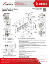
The following diagrams indicate possible installation methods. Determine
whether optional “Header Extension Bracket” or “Z” bracket” is required to
complete the installation. Suits door thicknesses of 1-1/4” to 1-3/4” [32 to
45mm]. (MGL-06000ALS shown)
Typical out-swinging door using the standard mounting plate.
Typical out-swinging door using a “Header Extension Bracket”
to extend the header depth.
•
Use the supplied template to determine the correct location and size of
mounting holes for both the door and frame header. Ensure that the door
opens away from the Maglock. In the case of a single door, the Maglock is
positioned as close as possible to the vertical section of the door jamb.
• Loosely install the mounting plate using two of the supplied philips
head mounting screws in the elongated slots. Attach the Maglock to the
mounting plate.
Product Specification:
•
Holding Force - MGL-06000ALS Series: 1200 lbs (544 Kg)
MGL-03000ALS Series: 600 lbs (272 Kg)
MGL-01500ALS Series: 300 lbs (136 Kg)
•
12 & 24 volts DC operation (selectable).
Note: Factory default setting is 12VDC.
Product Type:
•
Besides unmonitored version, all series locks have either magnetic bond
sensor (MBS) or door position switch (DPS) or both.
•
•
For MGL-06000ALS and MGL-03000ALS Series, magnetic bond sensor
uses hall effect sensor.
For MGL-01500ALS Series, uses change-over reed switch sensor.
•
For MGL-06000ALS and MGL-03000ALS Series, door position sensing uses
change-over reed switch sensor.
MGL-06000ALS and MGL-03000ALS Series with MBS:
•
For MGL-06000ALS and MGL-03000ALS Series, the LED operation color can be
field set. The colors can be reversed simply by reversing the 2 pin plug connection
on the PCB.
•
There is no LED for MBS on the MGL-01500ALS Series
•
The factory default setting is as follows:
LED indicator off
(No power to the magnet)
LED indicator red (Power on magnet, door open)
LED indicator green
(Power on magnet, door closed)
•
Note: where the Maglock has both MBS and DPS, the LED
indicates as per the MBS model.
Product Dimensions (L x W x H):
MGL-06000ALS Series - 10-1/2” x 2-7/8” x 1-9/16” [266mm x 72mm x 40mm]
MGL-03000ALS Series - 9-3/8” x 1-7/8” x 1-1/6” [238mm x 48mm x 26.5mm]
MGL-01500ALS Series - 6-11/16” x 1-5/8” x 7/8” [170mm x 41.4mm x 22.8mm]
Installation Requirements:
• Adjust onboard PCB shunt settings for correct operating voltage prior to
applying power to the EML.
For 12 volts two shunts must be installed:
- First shunt joining pins 1 & 2
- Second shunt joining pins 3 & 4.
For a 24 volt system only one shunt is required, joining pins 2 & 3.
1
2
4
5
MGL-01500ALS, MGL-03000ALS & MGL-06000ALS Series Maglock Installation Instructions
PRODUCT INFORMATION
PRODUCT INSTALLATION AND WIRING
3
DETERMINE MOUNTING METHOD
Typical in-swinging door installation using “Z Bracket” kit.
MOUNTING THE MAGLOCK
ATTACHING THE MOUNTING PLATES
HEADER EXTENSION
BRACKET
For MGL-06000ALS and MGL-03000ALS Series, the signal is give

• Align the armature plate on the door using sight or the template supplied.
•
Mark and drill holes then mount the armature to the door. Make sure that the
armature plate is not over tightened and that it is installed as shown in the
following diagram. The armature plate must be free to self align with the door.
Assemble Glass Door
brackets as shown.
Connect electrical wiring according to the local appropriate wiring rules.
Make sure the correct voltage on the PCB has been selected prior to turning
on the power. Failure to do this could damage the unit. Factory default
voltage is set to 12volts DC.
Note: If a door closer has been fitted then adjust it so that the
armature closes lightly against the magnet. This will avoid damage to
the magnet and will also make the door operation quieter.
The electromagnet lock does not require much ongoing maintenance. The
customer should be advised to keep the mating faces of the armatur
e
and magnet clean making sure that no abrasive materials are used to
clean the faces.
Do not spray the magnet or armature with any
chemicals such as lacquer as the release of the
Maglock may be compromised.
6
7
MOUNTING THE ARMATURE
HOLLOW CORE
DOOR ENLARGE
HOLE TO 16mm
SOLID CORE
DOOR ENLARGE
HOLE TO 12mm
MOUNTING ARMATURE
ON DIFFERENT DOOR TYPES
ADJUST POSITION OF
MAGNET RELATIVE TO
THE ARMATURE
•
Ensure the armature and magnet are aligned.
Adjust the mounting plate to suit and then drill
the appropriate sized holes in the door header
for the remaining attachment screws.
MOUNTING THE MAGLOCK
MOUNTING WITH Z BRACKET KITS
Assemble Z Bracket kit as shown
MOUNTING ON GLASS DOORS
ELECTRICAL CONNECTION
MAINTENANCE
REINFORCED
DOOR
TAP M6 X 1.0 for
TAP M8 X 1.25 for
MGL-06000ALS
305130202A00000
MGL-01500ALS,
MGL-03000ALS
/